Table of Contents
Advertisement
Quick Links
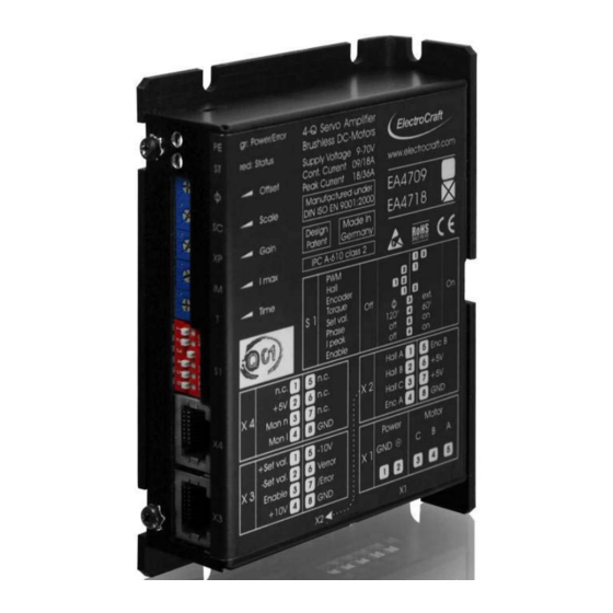
User Manual EA4709 / EA4718
4–Q PWM Servo – 09 / 18 A
EA4709 / EA4718
•
Servo amplifier in a small size, rugged aluminium housing in (bookshelf form)
•
Different methods of mounting for fast installation
•
Tool free connections for power terminations
•
Inputs and outputs via RJ45-CAT5 plug
•
Operation mode with simple DIP switch setting
•
User adjustable current limit and ramp function
•
Wide range supply voltage between +9 and +70 VDC for different kinds of DC-power
supplies
•
Protected against overtemperature and over-current
•
MOSFet-technology, efficiency 97%
•
Continuous current up to 9 / 18 A (model dependent)
Basic drive description: The EA4709 / EA4718 servo amplifiers are designed to drive DC
brushless type motors. They require a single DC power supply for operation. The drives
are to be used with a single motor. They have the functionality to operate as an
independent speed control or high performance servo. The drives are protected against
short circuits, under voltage, over temperature, and over current. It has multiple modes of
operation and serves as a reliable choice for your motion control needs.
ElectroCraft
For Brushless-Commutated DC Motors up to 1260 W
®
E-Mail: info@electrocraft.com
1
www.electrocraft.com
May 2009
Advertisement
Table of Contents

Subscribe to Our Youtube Channel
Related Manuals for ElectroCraft EA4709


Summary of Contents for ElectroCraft EA4709
- Page 1 • Continuous current up to 9 / 18 A (model dependent) Basic drive description: The EA4709 / EA4718 servo amplifiers are designed to drive DC brushless type motors. They require a single DC power supply for operation. The drives are to be used with a single motor. They have the functionality to operate as an independent speed control or high performance servo.
-
Page 2: Table Of Contents
User Manual EA4709 / EA4718 Table of Contents Safety & Installation ................. 3 Specifications: .................. 4 Drive Overview .................. 7 Wiring ....................10 Explanation of Terminals, Dip Switches, & Potentiometers ..21 Glossary ..................25 Description of Inputs and Outputs ..........31 Basic Troubleshooting .............. -
Page 3: Safety & Installation
Improper wiring could cause a “motor run away” condition, and cause serious injury or damage to the machine and personal. Before starting installation of the EA4709 / EA4718, be sure that main power is disconnected. After powering the drive it should not be touched by hand or risk shock. -
Page 4: Specifications
User Manual EA4709 / EA4718 Specifications: Electrical Data Power Supply Voltage +9 to +70 VDC (Residual ripple <5 %) (The lower limit monitored integrated undervoltage trip) WARNING: Do not exceed 70V. Overvoltage will damage the drive. Auxiliary Voltage Input +5 to +30 VDC Supply voltage for the /Error output. - Page 5 User Manual EA4709 / EA4718 Mechanical Data Mechanical Dimensions L x W x H 120 x 85 x 27.5 mm Weight 210 g Mounting M3 screws or Din Rail Mounting Ambient Conditions Operation Temperature -10 to +45 Storage Temperature -40 to +85...
- Page 6 User Manual EA4709 / EA4718 Control LEDs Power/Error LED green Status LED red Status Table State LED green LED red /Error-Output Reset Reset / Selftest On / Off Normal HIGH Hall error Flash 5x/s Enable Encoder error Long flash 1x/s...
-
Page 7: Drive Overview
User Manual EA4709 / EA4718 Drive Overview Block Diagram ® ElectroCraft E-Mail: info@electrocraft.com www.electrocraft.com May 2009... - Page 8 User Manual EA4709 / EA4718 Input & Output Schematics ® ElectroCraft E-Mail: info@electrocraft.com www.electrocraft.com May 2009...
- Page 9 User Manual EA4709 / EA4718 Control Elements Operation Modes PWM Mode In the PWM mode the input voltage of the set value is directly converted to a PWM-signal at the output. The drive works in open loop and the complete regulation circuit is switched off.
-
Page 10: Wiring
User Manual EA4709 / EA4718 Wiring According to the safety directives, a correct cable selection is mandatory. Regular inspection is advisable. Damaged, burned or kinked items have immediately to be exchanged. Power (Power ⊕ - Power GND) • Normally no shielding required. - Page 11 User Manual EA4709 / EA4718 4.1 Wiring Example I – Hall Mode ® ElectroCraft E-Mail: info@electrocraft.com www.electrocraft.com May 2009...
- Page 12 User Manual EA4709 / EA4718 4.1.1 Adjustment procedure for Hall mode 1. Potentiometer pre setting refer chapter 5.2. 2. Choose the maximum set value (e.g. 10 V). Turn the potentiometer Scale , until the desired maximum speed is reached. If the red LED is flashing 5x/s the maximum speed is reached, depending on the supply voltage.
- Page 13 User Manual EA4709 / EA4718 4.2 Wiring Example II – Encoder Mode ® ElectroCraft E-Mail: info@electrocraft.com www.electrocraft.com May 2009...
- Page 14 User Manual EA4709 / EA4718 4.2.1 Adjustment procedure for Encoder mode 1. Potentiometer pre setting refer chapter 5.2. 2. Choose the maximum set value (e.g. 10 V). Turn the potentiometer Scale, until the desired maximum speed is reached. If the red LED is flashing 5x/s the maximum speed is reached, depending on the supply voltage.
- Page 15 User Manual EA4709 / EA4718 4.3 Wiring Example III – Torque Mode ® ElectroCraft E-Mail: info@electrocraft.com www.electrocraft.com May 2009...
- Page 16 User Manual EA4709 / EA4718 4.3.1 Adjustment procedure for Torque mode 1. Potentiometer pre setting refer chapter 5.2. 2. Adjust the current limiter to a value requested by you with the I max potentiometer. It is of major importance that this value is lower than the maximum admissible constant current (see motor data sheet).
- Page 17 User Manual EA4709 / EA4718 4.4 Wiring Example IV – PWM Mode ® ElectroCraft E-Mail: info@electrocraft.com www.electrocraft.com May 2009...
- Page 18 User Manual EA4709 / EA4718 4.4.1 Adjustment procedure for PWM mode 1. Potentiometer pre setting refer chapter 5.2. 2. Choose the maximum set value (e.g. 10 V). Turn the potentiometer Scale, until the desired maximum speed is reached. If the red LED is flashing 5x/s the maximum speed is reached, depending on the supply voltage.
- Page 19 User Manual EA4709 / EA4718 Wiring Example V Setting of S1: Hall Mode: Encoder Mode Torque Mode PWM Mode ® ElectroCraft E-Mail: info@electrocraft.com www.electrocraft.com May 2009...
- Page 20 User Manual EA4709 / EA4718 Wiring Example VI Setting of S1: (For Enable switch S1/6 from off to on.) Hall Mode: Encoder Mode Torque Mode PWM Mode ® ElectroCraft E-Mail: info@electrocraft.com www.electrocraft.com May 2009...
-
Page 21: Explanation Of Terminals, Dip Switches, & Potentiometers
User Manual EA4709 / EA4718 Explanation of Terminals, Dip Switches, & Potentiometers 5.1 Terminals Terminal Label Description S1-1; S1-2 select mode. S1-3 change set value to Offset-pot. S1-4 select the phase of the halls. S1-5 select Ipeak on or off. - Page 22 User Manual EA4709 / EA4718 5.2 Potentiometers Potentiometer Function Turning to the Left Turning to the Right (ccw) (cw) Zero Offset (motor stands Motor rotates Clockwise rotation Offset still) counterclockwise Definition of max. number Value is decreased Value is increased...
- Page 23 User Manual EA4709 / EA4718 S1-3 Set val. Methods of entering the set value Off: Set val. intern The internal Offset potentiometer is used. Set val. extern External selection using a voltage between X3/1 and X3/2. S1-4 Phase Setting of the Hall arrangement Off: Phase 120°...
- Page 24 User Manual EA4709 / EA4718 Setting Hall Mode: Encoder Mode Torque Mode PWM Mode Set value intern Phase 120° Ipeak off Set value extern Phase 120° Ipeak off Set value intern Phase 120° Ipeak on Set value extern Phase 120°...
-
Page 25: Glossary
User Manual EA4709 / EA4718 Glossary Offset There are two distinct functions for the Offset-Potentiometer: 1. Levelling the position at which the motor stands still. 2. Selection of the Set Value. This task requires the switch S1-3 (Set val.) to be in Off position. - Page 26 User Manual EA4709 / EA4718 I max The following action requires the motor to be operated with maximum load. The motor current may be measured e.g. using current probe with effective value display, or by means of an ammeter located in the motor line.
- Page 27 User Manual EA4709 / EA4718 Hall mode This is a closed loop speed mode which is using the hall signals as a feedback input for the speed. Encoder mode This is a closed loop speed mode that receives the speed information from the encoder.
- Page 28 User Manual EA4709 / EA4718 Encoder Is a feedback device which converts mechanical motion into electronic signals. The most commonly used, rotary encoders, output digital pulses corresponding to incremental angular motion. For example, a 1000-line encoder produces 1000 pulses every mechanical revolution.
- Page 29 User Manual EA4709 / EA4718 Demag current Is the current level at which the motor magnets will start to be demagnetized. This is an irreversible effect, which will alter the motor characteristics and degrade performance. Drive It‘s an electronic device that controls torque, speed and/or position of an AC or brushless motor.
- Page 30 User Manual EA4709 / EA4718 NTC - Negative Temperature Coefficient A negative temperature coefficient thermistor is used to detect and protect a motor winding from exceeding its maximum temperature rating it is also used in a servo amplifier. Resistance of the device decreases with an increase in temperature.
-
Page 31: Description Of Inputs And Outputs
User Manual EA4709 / EA4718 Thermal protection A thermal sensing device mounted to the motor to protect it from overheating. This is accomplished by disconnecting the motor phases from the drive in an over temperature condition. Torque Is a measure of angular force which produces rotational motion. This force is defined by a linear force multiplied by a radius;... - Page 32 User Manual EA4709 / EA4718 Digital Outputs /Error: Monitoring Output Whenever a system failure occurs (i.e. overtemperature or hall error), the /Error output responds (LO position), and the green LED on the front panel is switch off. The drive output stage is switched off and the error will not reset until the user resets the drive by switching the enable input.
- Page 33 User Manual EA4709 / EA4718 Analog Inputs +Set val. –Set val.: Inputs for Set Values An external +10/-10 V analog signal for speed or for current is entered using +Set val and – Set val inputs. If the effective voltage is 0V, the motor stops. If the effective voltage is positive, the motor moves in one direction.
- Page 34 Mon I: Motor Current Output Monitor I delivers a result representing the actual value of the average motor current. The proportionality factor is fixed to 1V (EA4709) / 0.5V (EA4718) per 1A motor current. Additional information about the schematic refer chapter 3.2.
-
Page 35: Basic Troubleshooting
User Manual EA4709 / EA4718 Basic Troubleshooting The servo amplifier has included some different protective functions. Over voltage, over temperature, hall error, encoder error and over current are monitored and shown in an error trap with the two LED’s at the front side which error has occurred. The table is described in chapter 2.7. - Page 36 User Manual EA4709 / EA4718 Motor speed too low • Increase the range with pot Scale. • Increase the admissible current with I max pot. • Supply voltage too low. • Encoder input frequency is to high, use an encoder with a lower resolution.
-
Page 37: Accessories & Options
User Manual EA4709 / EA4718 Accessories & Options • Mounting adaptor for Din rail MA0025 • Connecting module WA2509 • Choke modules IA3100 (with 3 x 50 µH) and IA3101 (with 3 x 100 µH) • Heatsink ( No Fan) HA3008 •... -
Page 38: Warranties & Disclaimers
• Contents are subject to change without notice. • Electrocraft will not be liable in any way for direct, indirect, incidental, or consequential damages caused by the use of this product or document. • Per Electrocraft’s Terms & Conditions, the user of Electrocraft’s accepts all responsibility and risks involved with applying this product into their machinery and indemnifies Electrocraft against all damages. -
Page 39: Dimensions
User Manual EA4709 / EA4718 11. Dimensions 27.5 85.0 4 x 3.4 2 x 3.4 14.0 10.0 50.0 All dimensions in mm. 12. Mounting Din rail adapter DIN7982 3,5x9,5 EA47xx_E09 Subject to change without prior notice. ® ElectroCraft E-Mail: info@electrocraft.com www.electrocraft.com...
Need help?
Do you have a question about the EA4709 and is the answer not in the manual?
Questions and answers