
Subscribe to Our Youtube Channel
Related Manuals for Sagola PACK 6000X


Summary of Contents for Sagola PACK 6000X
- Page 1 m a n u a l d e i n s t r u c c i o n e s l i s t a d e r e p u e s t o s i n s t r u c t i o n m a n u a l l i s t o f s p a r e p a r t s...
- Page 3 Índice Atención pág. 4 Introducción pág. 4 Datos Técnicos pág. 4 Componentes. Principales partes y zonas pág. 5 Principios de funcionamiento pág. 5 Advertencias pág. 6 Consejos Útiles pág. 6 Mandos e indicadores pág. 7 Controlador de temperatura pág. 7 Interruptor general de potencia pág.
-
Page 4: Datos Técnicos
El equipo de aire comprimido PACK 6000X AIR La utilización de este equipo aporta una óptima HEATER, según los ajustes establecidos “por calidad de acabado manteniendo una temperatu- defecto”... -
Page 5: Principios De Funcionamiento
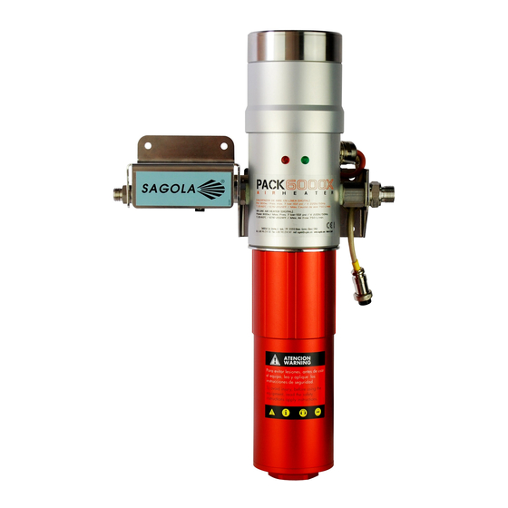
4. COMPONENTES. PRINCIPALES PARTES Y ZONAS 1.- Mandos 2.- Interruptor general 3a.- Piloto rojo (Calentado) 3b.- Piloto verde (Preparado) 4.- Sensor de temperatura 5.- Flujostato 6.- Cámara de aire frío, (despresurizada) 7.- Cámara de aire caliente (presurizada) 8.- Entrada de aire (por el filtro de aire) 9.- Salida de aire (manguera) 10.- Conexión eléctrica (manguera calefactada) -
Page 6: Consejos Útiles
- ES IMPRESCINDIBLE tener instalado un interruptor diferencial para la línea de alimenta- - Lea y aplique con atención todas los datos, ción del PACK 6000X. En el caso contrario tener instrucciones y medidas de seguridad indicados como mínimo instalado un interruptor magnetotér- por el fabricante de los productos que vaya a mico de 2 polos (1P + N). - Page 7 150 litros / minuto como caudal mínimo para su funcionamiento. Queda terminantemente prohibido manipular el flujostato sin consulta previa con SAGOLA S.A. LA MANIPULACION DE ESTE COMPONENTE PUEDE PONER EN RIESGO EL BUEN FUNCIONAMINETO DEL EQUIPO No hacer caso a esta advertencia puede ocasionar la destrucción de la resistencia y en...
- Page 8 Aloja los siguientes elementos: 8.6 CAMARA DE AIRE FRIO, (DESPRESURIZADA) - Resistencia 800W Aloja los siguientes elementos: - Fusible térmico tarado a 216 - Relé de potencia - Funda de la resistencia para canalizar el aire. - Controlador de temperatura - Fusible por intensidad 5A (220-240V) ó...
- Page 9 BSPP, capaz de suministrar como mínimo disposición el manual de instrucciones del equipo. 150l/min. (Demandados por el equipo PACK En caso de duda consulte al S.A.T. de SAGOLA. 6000X Air Heater). - Que la persona destinada a programar, desmon- 9.2.2. Conexión a la...
- Page 10 Fusible por intensidad amarre del PACK 6000X AIR HEATER, en el El equipo está provisto de un fusible por aumento pliegue previsto para tal fin.
-
Page 11: Puesta En Marcha
10. PUESTA EN MARCHA 10.1 INSTALACIÓN do del piloto “Preparado”, cuando se realicen paradas con corte de consumo de aire. - Desembale el equipo. - Preste especial atención al piloto “Preparado” y - Posiciónelo en su ubicación. no trabaje cuando el piloto “Preparado” esté apagado. -
Page 12: Mantenimiento Y Reparaciones
ASISTENCIA TÉCNICA (SAT) DE SAGOLA S.A. Los trabajos de mantenimiento y reparación del equipo solo deben ser realizados por personal SAGOLA S.A. se reserva el derecho de no autorizado por SAGOLA, S.A. autorizar la realización de determinados trabajos en el equipo. - Page 13 SAGOLA, S.A. no se responsabiliza de estos Recomendamos que utilicen productos que no daños producidos por el mal uso del equipo.
-
Page 14: Condiciones De Garantía
No se atenderá en garantía ningún aparato del aparato. Asimismo se perderá la GARANTÍA cual no conste en los archivos de SAGOLA S.A. el cuando se constate que el aparato ha sido resguardo adjunto, del certificado de garantía manipulado por personas ajenas a nuestro debidamente cumplimentado. - Page 15 Index Attention page 16 Introduction page 16 Technical Data page 16 Components. Main parts and areas page 17 Operating principles page 17 Warnings page 18 Useful Tips page 18 Controls and indicators page 19 Temperature controller page 19 Main power switch page 19 “Ready”...
-
Page 16: Technical Data
2. INTRODUCTION The equipment you have purchased and within One of its main applications is to supply the the SAGOLA product range, belongs to the family compressed air used in painting processes at a of equipment used to project compressed air constant temperature, regardless of the environ- through a spray gun or as an application tool. -
Page 17: Operating Principles
4. COMPONENTS. MAIN PARTS AND AREAS 1.- Controls 2.- Main switch 3a.- Red led (Heating) 3b.- Green led (Ready) 4.- Temperature sensor 5.- Flow meter 6.- Cold air chamber, (depressurised) 7.- Hot air chamber, (pressurised) 8.- Air inlet (from air filter) 9.- Air outlet (hose) 10.- Electrical connection (heated hose) 5. -
Page 18: Useful Tips
PACK 6000X by directly removing the plug from and people around him (See section on Health the plug or turning off the 2-pole circuit breaker (1P and Safety). -
Page 19: Controls And Indicators
150 litres / minute as the minimum flow for its operation. It is strictly forbidden to manipulate the flow switch without prior consultation with SAGOLA S.A. MANIPULATION OF THIS COMPONENT MAY PUT THE PROPER OPERATION OF THE EQUIPMENT AT RISK... -
Page 20: Pre-Installation
Contains the following components: 8.6 COLD AIR CHAMBER, (DEPRESSURISED) - 800W resistance Contains the following components: - Thermal fuse set to 216 - Power relay - Cover of the resistance for channelling the air. - Temperature controller - 5A fuse (220-240V) or 10A (110-130V) 8.8 HEATED HOSE - Resistance activation pilot light Hose specially designed to avoid loss of heat from... - Page 21 - To the compressed air grid and the connection to and perform maintenance tasks 14” BSPP, capable of supplying at least 150l/min. (Required by the PACK 6000X Air Heater and repair the equipment has adequate knowled- equipment). ge of the electrical, mechanical and pneumatic aspects.
- Page 22 After it having been rendered inactive by reaching you fit the protective cover on the anchoring plate a temperature of 216ºC it must be replaced. of the PACK 6000X AIR HEATER, in the groove Please contact SAGOLA's Technical Assistance provided for this purpose.
-
Page 23: Programming And Adjustments
10. STARTING UP 10.1 INSTALLATION - Start working. Check that the “Ready” pilot light turns on and off when stops are made with a - Unpacking the equipment. cut-off in air consumption. - Position it in its location. - Pay special attention to the “Ready” pilot light and do not work when the “Ready”... -
Page 24: Maintenance And Repairs
TECHNICAL ASSISTANCE SERVICE (TAS) air grid and the mains and depressurise it. Maintenance and repair tasks on the equipment SAGOLA S.A. reserves itself the right to not may only be done by personnel authorised by authorise the performance of certain tasks on the SAGOLA, S.A. - Page 25 As a result, such components can oxidise and in SAGOLA, S.A. shall not be held liable for the extreme cases, the arising chemical reaction may improper use of the equipment.
-
Page 26: Guarantee Conditions
No device will be serviced under guarantee that is not attributable to the manufacturing of the device. not recorded in the files of SAGOLA S.A. of the Also the GUARANTEE shall be lost when it is attached duly completed guarantee certificate. - Page 27 C O N D I C I O N E S D E G A R A N T Í A G U A R A N T E E C 0 N D I T I O N S C O N D I T I O N S D E G A R A N T I E G A R A N T I E B E N D I N G U N G E N C O N D I Ç...
- Page 28 SAGOLA S.A. Urartea, 6 · 01010 Vitoria-Gasteiz · ESPAÑA Tel.: +34 945 214 150 · Fax: +34 945 214 147 e-mail: sagola@sagola.com · web: www.sagola.com...
Need help?
Do you have a question about the PACK 6000X and is the answer not in the manual?
Questions and answers