Advertisement
Quick Links
Chrysler IIIH Engine Assembly Manual
R
Revision Release Date:
1 , 201
Engineering Contact:
Jeff Betz
313-363-8093
Fiat Chrysler America
This document is to be used as a supplement to the Chrysler Sequence IIIH Engine Oil
Certification Test, (ASTM Standard Test Method D
), and is used in conjunction with the
Standard Test Method to outline test engine build and assembly instructions.
Advertisement

Related Manuals for Chrysler IIIH


Summary of Contents for Chrysler IIIH
- Page 1 Jeff Betz 313-363-8093 Fiat Chrysler America This document is to be used as a supplement to the Chrysler Sequence IIIH Engine Oil Certification Test, (ASTM Standard Test Method D ), and is used in conjunction with the Standard Test Method to outline test engine build and assembly instructions.
- Page 2 Section 0 Document Index 0) Document Index 1) Engine Specifications and Fastener Torque 2) Precautionary Statements & Cylinder Head Core Preparation 3) New Engine Disassembly 4) Main Oil Gallery Modifications and Honing 5) Post Honing and Special Parts Cleaning 6) Cylinder Head Pre-Build Cleaning and Assembly 7) Short Block Assembly and General Information 8) Long Block Assembly 9) Final Dress...
- Page 3 Revision 1 Section Chrysler IIIH Engine Specifications June‐18 Sheet Description Specification General Information 60° DOHC V‐6 24 Valve Engine Family 10.2 : 1 Compression Ratio #1 Right Bank Lead Cylinder Firing Order 1‐2‐3‐4‐5‐6 Metric Standard 3.6 Liters 220 Cubic Inches Displacement 96.0 x 83.0 mm 3.779 x 3.268 in. Bore and Stroke Cylinder Block Metric Standard 96.04 3.781 Cylinder Bore Diameter (Test Target) 0.009 mm 0.00035 in. Cylinder Bore Out‐of‐Round (Max.) 0.015 mm 0.0006 in. Cylinder Bore Cylindricity Pistons Metric Standard Piston Diameter (Metal to Metal) Clearance at Size Location (Metal to Metal)
- Page 4 Revision DRAFT Section Chrysler IIIH Engine Specifications Mar‐16 Sheet Description Specification Connecting Rods Metric Standard 0.023 ‐ 0.064 mm 0.0009 ‐ 0.0025 in. Bearing Clearance (With Crush) 0.070 ‐ 0.370 mm 0.0028 ‐ 0.0146 in. Side Clearance 22.016 ± 0.005 mm 0.8668 ± 0.0002 in. Piston Pin Bore Diameter Bearing Bore Out of Round (Max.) 0.008 mm 0.0003 in. Metric Standard Crankshaft Main Bearing Journals 71.996 ± 0.009 mm 2.8345 ± 0.0035 in. Diameter 0.024 ‐ 0.050 mm 0.0009 ‐ 0.0020 in. Bearing Clearance Out of Round (Max.) 0.005 mm 0.0002 in. 0.050 ‐ 0.290 mm 0.002 ‐ 0.0114 in. Crankshaft End Play Metric Standard Crankshaft Rod Bearing Journals 59.0 ± 0.009 mm...
- Page 5 Revision 1 Section Chrysler IIIH Torque Specifications June‐18 Sheet N∙m Lb. Ft. Lb. In. Camshaft Chain Tensioner (Primary) M6 T30 Camshaft Chain Guide (Primary) M6 T30 Camshaft Chain Idler Sprocket M8 T45 Camshaft Chain LH Tensioner (Secondary) M6 T30 Camshaft Chain LH Guide (Secondary) M6 T30 Camshaft Chain RH Tensioner (Secondary) M6 T30 Camshaft Chain RH Guide (Secondary) M6 T30 Camshaft Position (CMP) Sensor to Cylinder Head M6 T30 Camshaft Bearing Cap M6 T30 Connecting Rod Cap M9 Bolt 20 + 90° 15 + 90° Coolant Pump Plate to Engine Timing Cover M6 Bolt Coolant Crossover Plate to Engine Timing Cover M6 Bolt Coolant Pump Plate to Engine Timing Cover M10 Bolt Crankshaft Target Wheel to Counterweight M6 T30 Crankshaft Outer Main Bearing Cap and Windage Tray M8 Bolt 21 + 90° 16 + 90° Crankshaft Inner main Bearing Cap M11 Bolt 20 + 90° 15 + 90° Crankshaft Side Main Bearing Cap (Tie Bolt) M8 Bolt Crankshaft Vibration Damper M16 Bolt 40 + 105° 30 + 105° Crankshaft Position (CKP) Sensor to Engine Block M6 Bolt Crankshaft Rear Oil Seal Retainer M6 T30 Cylinder Head Oil Gallery Plug Cylinder Head Oil Restrictor M8 Plug Cylinder Head to Engine Block M12 in Sequence See IIIH Assembly Manual Section 8 Cylinder Head / Camshaft Cover M6 Bolt...
- Page 6 Revision 1 Section Chrysler IIIH Torque Specifications June‐18 Sheet Description N∙m Lb. Ft. Lb. In. Knock Sensor to Engine Block Oil Control Valve ‐ Cam Phaser M8 Bolt Upper Oil Pan to Engine Block M8 Bolt Oil Cooler to Oil Filter Housing Screws Upper Oil Pan to Rear Seal Retainer M6 Bolt Oil Pan Drain Plug M14 Oil Pressure Sensor to Oil Filter Housing Oil Temperature Sensor to Oil Filter Housing Piston Oil Cooler Jet to Engine Block M5 Oil Filter Housing / Oil Cooler to Engine Block M6 Oil filter Housing Cap Oil Pump to Engine Block M6 Bolt Oil Level Indicator to Engine Block M10 Bolt Oil Level Indicator to Cylinder Head M6 Bolt Oil Pump Sprocket M8 T45 Oil Pump Pickup Tube Bracket to Windage Tray M6 Bolt Oil Pump Pickup Tube to Oil Pump M6 Bolt Oxygen Sensor to Exhaust Take Down Pipe M18 PCV Valve M5 T25 Spark Plug to Cylinder Head M12 Starter Mounting M10 Bolt Tensioner to Engine Timing Cover Accessory Drive M10 Bolt Thermostat Housing to Coolant Crossover M6 Bolt Throttle Body M6 Bolt Engine Timing Cover M6 Bolt Engine Timing Cover M8 Bolt Engine Timing Cover M10 Bolt Upper Intake Manifold Support Bracket to Upper Intake Manifold M8 B Upper Intake Manifold Support Bracket to Upper Intake Manifold M6 N Variable Valve Timing Solenoid to Cylinder Head Cover M5 T25 Wire Harness Retainer Bracket to LH Cylinder Head M6 T30...
- Page 7 Revision 1 Section Precautionary Statements June‐18 Sheet Caution: The 3.6L Pentastar Engine is NOT A FREE SPIN ENGINE. Care must be exercised during disassembly not to rotate the crankshaft or camshafts once the valvetrain chain assemblies have been altered in any manner. Caution: Do not lay cylinder heads on gasket sealing surfaces. The design of the Multi‐Layer Steel (MLS) cylinder head gasket will not seal properly if there are any imperfections on the cylinder head or engine block. Plastic type gasket removing tools have been found suitable when cleaning these surfaces. NOT A FREE SPIN ENGINE Warning: Valve to Piston interference will occur if not Multi‐Layer Steel (MLS) head gaskets have very sharp edges properly disassembled / assembled that could cause personal injury if not handled carefully. Note: Multi‐Layer Steel gaskets require a scratch free sealing surface. Remove all gasket materials from cylinder head and block using care not to gouge or scratch the aluminum sealing surfaces. Non compressible debris such as oil, coolant, or RTV sealants not removed from bolt holes can cause the aluminum cylinder block to fracture when tightening fasteners. Clean all cylinder head bolt holes in the engine block. Do not use any sealants or adhesives on fasteners, Multi Layer Gaskets, or any sealing surfaces unless specified in this procedure. Surfaces must be debris free and scratch free for proper sealing. Notes:...
- Page 8 Revision 1 Section Cylinder Head Core Preparation June‐18 Sheet New engines are ordered through Chrysler MOPAR under special order part number. Engines are preserved under long term packaging. Once received at the test laboratory, they should be disassembled and put into storage for future build. Cylinder heads should be completely disassembled and the valvetrain gear stored for future use. Bare cylinder heads (Cores)should be sent to IMTS for re‐ work. Labs must use the IMTS Special Packaging to protect the cores from damage. Packaging contains special cushioning sleeves for both Right and Left cylinder heads. Camshaft caps are identified on the sides, "1E‐> , 2E‐>" etc. for exhaust camshafts and "1I‐> , 2I‐>" etc. for intake camshaft caps. Caps must be kept in order. Remove all valvetrain hardware from cylinder heads; camshafts, roller rockers, lash adjusters, valve springs, valve seals, and spark plugs. Keep all camshaft bearing caps in order. Replace after Do not remove oil gallery plugs or freeze plugs valvetrain hardware removal. Do not use impact tools to tighten camshaft caps. Use a speed handle to lightly snug fasteners and torque M6 T30 fasteners to 9.5 Nm. After removing all valvetrain gear and torqueing all camshaft caps in their proper position, install the cylinder head in VCI bag and insert the assembly in the IMTS Packaging with proper inserts, Securely tape package and ship to: IMTS 8460 Ronda Dr. Canton, MI. 48187 Top insert rotates 180° depending which head, left or right is in box.
- Page 9 Section 3 New Engine Disassembly...
- Page 10 Revision DRAFT Section New Engine Disassembly Mar‐16 Sheet New engines are received from Chrysler as full assemblies. Upon delivery to the build area, they should be disassembled and prepared for test. Cylinder heads should be disassembled and the bare heads need to be packaged for shipment to IMTS for special processing. Packaging from the new cylinder heads to be used for the test should be used for return of new core materials to IMTS. Remove the flywheel and disengage the ignition and fuel injector harness clips on the upper intake manifold brackets (1). Remove both upper intake manifold brackets (2). Remove PCV vacuum tube from rocker cover to Remove upper intake manifold (2) fasteners (1) upper intake manifold. ...
- Page 11 Revision DRAFT Section New Engine Disassembly Mar‐16 Sheet Disconnect all injection harness and ignition harness retainer clips. Disconnect coil pack electrical connectors. Disconnect fuel injector electrical connectors from fuel injectors. Remove harness. Remove the eight lower intake manifold attaching Remove the lower intake manifold (2) with the fuel bolts (1). injectors and fuel rail. The lower intake manifold is an injection molded nylon composite design. The lower intake seals to the cylinder heads using six individual silicone gaskets. The seven upper intake manifold fasteners thread directly into the composite lower intake manifold and are self‐tapping design. The fuel rail is also a composite design. The four fuel rail fasteners thread directly into the lower intake manifold and also are self‐tapping design. The fuel rail and fuel injectors must be installed into the lower intake manifold as an assembly. Do not attempt to install the fuel rail when the injectors are in the manifold. Seal, Lower Intake to Cylinder Head 051844331AC (Six individual seals) Seal, Lower Intake to Upper Intake 05184562AC (Six individual seals)
- Page 12 Revision 1 Section New Engine Disassembly Jun‐18 Sheet Install the Driver Side Engine Lifting Bracket 10242‐1 (1) on the LH cylinder head with bolts (2) provided with the Engine Lifting Bracket. Tighten the bolts to 21 N∙m (15 ft. lbs.). Install the Passenger Side Engine Lifting Bracket 10242‐2 (1) on the RH cylinder head with bolts (2) from the Engine Lifting Bracket. Tighten the bolts to 21 N∙m (15 ft. lbs.). Labs may also chose to fabricate in‐house lifting brackets. Care should be taken to ensure the brackets keep all chains and hooks from contacting the camshaft covers. It has been found that plates attached to the exhaust manifold fastener area work well when moving fully assembled engines. Once positioned on the roll over stand, Remove the oil filter cap and filter cartridge, thereby allowing any oil in the filter housing to drain to the oil pan. Drain the factory fill engine oil from the oil pan before rotating the engine on the roll over stand. Remove the front balancer.
- Page 13 Revision DRAFT Section New Engine Disassembly Mar‐16 Sheet Remove Oil Filter Cap & Cartridge Remover the Right Engine Mount Bracket. Remove the idler pulley. Remove the coolant crossover and thermostat housing. Remove the coolant pump. Remove the serpentine belt tensioner. Drain Factory Fill Oil Remove the front balancer.
- Page 14 Revision DRAFT Section New Engine Disassembly Mar‐16 Sheet Drain all fluids in the engine, rotating the engine to remove as much oil from the oil pan as possible. Disconnect all harness retainer clips and connections from the oil filter housing sensors and coolant hose assembly. Remove the fasteners (2) holding the oil filter housing (1) and oil cooler to the engine valley. Do not remove the screws (1) and (3) holding the oil cooler to the oil filter housing. Oil Filter / Cooler Adapter O‐ring Kit 68191356AA Contains items (1) & (2)
- Page 15 Revision DRAFT Section New Engine Disassembly Mar‐16 Sheet Remove the Camshaft Position Sensors Remove Ignition Coils Remove PCV Housing Remove Camshaft Covers Part Numbers: Gasket, Right Side Cylinder Head Cover 05184595AE Gasket, Left Side Cylinder Head Cover 05184596AE Seal, O‐ring, Camshaft Phaser Control 05184855AB Seal, Camshaft Position Sensor 06509450AA Seal, Tube, Spark Plug Well 05184778AB Care should be used to prevent damage to the camshaft cover seals at the joint between the front cover and cylinder head by using a sharp putty knife to slice the RTV sealer in these areas as the cover is lifted from the cylinder head.
- Page 16 Revision 1 Section New Engine Disassembly Jun‐18 Sheet Remove the lower oil pan fasteners. A sharp, rigid putty knife has been found suitable to cut the RTV sealer between the lower and upper oil pans. Remove the lower oil pan. Remove the upper oil pan fasteners. Use the pry points to break the RTV bond. Apply pressure on the front of the upper oil pan while tapping with a plastic mallet to remove the assembly. Note: main cap side bolts have also been removed while removing upper oil pan fasteners.
- Page 17 Revision DRAFT Section New Engine Disassembly Mar‐16 Sheet Remove the engine timing chain front cover fasteners. Using an appropriate pry bar, break the RTV seal at the pry points between the front cover and block. Remove the engine timing chain front cover. Part Numbers: Gasket Kit, Chain Case Cover, Crossover Water Outlet 68078604AA Gasket, Pump, Water 68087340AA Gasket, Crossover, Water Outlet 05184454AE Seal, Crankshaft Oil, Front 68079589AA...
- Page 18 Revision DRAFT Section New Engine Disassembly Mar‐16 Sheet Caution: Camshaft timing alignment is not performed during engine disassembly. Once the timing chain assemblies are removed, do not rotate the crankshaft until the camshafts are removed. Remove all timing chain tensioners, guides, chains and the idler shaft. See Long Block Assembly for Part Numbers. Remove the camshafts, roller rockers, lash adjusters, cylinder head fasteners, and cylinder heads. Re‐install the camshaft bushing caps. Remove the valve springs, seals, shims, and valves and package the cylinder heads for shipping to IMTS for processing.
- Page 19 Revision DRAFT Section New Engine Disassembly Mar‐16 Sheet Remove the windage tray and main cap side bolts. Mark the positions on the connecting rods and remove the piston and rod assemblies. Remove the crankshaft and prepare the engine block for cleaning. Follow procedure for pre stressing and honing the block for test. Note: Idler shaft should be removed...
- Page 20 Section 4 Main Oil Gallery Modifications and Honing...
- Page 21 Cylinder Block Main Oil Gallery Revision DRAFT Section Thermocouple Installation Tools Mar‐16 Sheet The rear main oil gallery is modified to adapt an 1/8 thermocouple just below the mixing point where the oil cooler flow and the oil cooler by‐pass flow intermix as it enters the main oil gallery. Special modifications are required to perform these operations and are outlined in this section of the cleaning and pre‐hone preparations section of the manual. Special tooling fixtures and tools to perform this operation are required and provided through IMTS IMTS Chrysler 3.6L Thermocouple Tapping Fixture Assembly 151132‐F001 1. Thermocouple Tapping Fixture 151132‐F001 (Main Plate Less Total Assembly Components) 2. Thermocouple Tapping Jig 151132‐J001 3. Thermocouple Setting Fixture 151132‐F002 4. Thermocouple Tapping Jig Tools and Fasteners a. Clearance Drill 151132‐T001 b. Aircraft Drill Special 151132‐T002 c. NPTF Tap Special 151132‐T003 d. Oil Gallery Clean Plug 151132‐P003 e. Fixture Fasteners...
- Page 22 Cylinder Block Main Oil Gallery Revision DRAFT Section Thermocouple Modification Mar‐16 Sheet 1. Remove the main oil gallery access plug from the right side of the engine. Remove the Crankshaft Sensor from the right side of the engine. Coolant Jacket Plug 2. Remove the main oil gallery access plug from the left side of the engine. Coolant Jacket Plug Caution: Due to potential oil leakage. Do not remove front main oil gallery cup plug Remove the timing chain idler gear shaft 4. Remove the rear main oil gallery plug. 5. Remove all three piston cooling jet assemblies from the main oil gallery.
- Page 23 Cylinder Block Main Oil Gallery Revision DRAFT Section Thermocouple Modification Mar‐16 Sheet 6. Attach the main tooling fixture plate to the rear of the engine aligning the plate over the transmission dowel pins with five allen hex fasteners. 7. Install the oil gallery Clean Plug Assembly 151132‐P003 using EF‐411 or an assembly type grease on the leather seal to aid in preventing machining debris from entering the lower main oil gallery. Gently rock the plug assembly back and forth installing the tool until it bottoms in the oil gallery. 8. Using a 1/2 inch Drill Motor with the Clearance Drill 151132‐T001, drill a clearance hole through the rear China Wall of the engine block using the hardened bushing to guide the drill bit through the China Wall.
- Page 24 Cylinder Block Main Oil Gallery Revision DRAFT Section Thermocouple Modification Mar‐16 Sheet 9. Install the main oil gallery thermocouple drilling and tapping fixture 151132‐J001 to the rear of the engine. Note the round and triangular alignment pin combination on the fixture for ease of installation alignment. Secure the 151132‐J001 fixture using the toggle clamps and allen hex head fasteners. Fasteners (Snug Only) Alignment pins Toggle Clamps 10. Using a 1/2" drill motor with the Special Tip Aircraft Drill 151132‐T002, drill through the main oil gallery until the tip of the drill breaks through the inside. Note special cut tip on tool 151132‐T002 11. Using an appropriately sized Tee Handle with the special length tapping tool 151132‐T003 1/16" NPTF Tap, thread the drilled hole in the main oil gallery until the Yellow Ring on 151132‐T003 meets the hardened bushing guide on the tapping fixture 151132‐J001. Note, the use of a tapping lubricant or grease to hold machining debris is recommended. 12. After threading the main oil gallery, carefully remove all fixture tooling, leaving the Clean Plug Assembly in the main gallery. Using preferred laboratory cleaning practice, clean the threads and any machining debris from the main oil gallery. Carefully remove the Clean Plug Assembly and inspect the threaded hole for any burrs or sharp edges on the inside of the main oil gallery.
- Page 25 2. If desired, chase all threaded bolt holes for the cylinder head bolt holes and the main cap bolt holes using cleaning thread chase taps. Avoid using thread cutting type taps to clean threads. Thread cleaning taps are available through sources such as ARP, Snap‐on, or Mac Tools for SAE and Metric thread sizes. Caution: Non compressible debris such as oil, coolant, or RTV sealants not removed from bolt holes can cause the aluminum cylinder block to fracture when tightening fasteners. 3. Clean the engine block prior to honing using either of the following methods; a. Clean in the spray booth using degreasing solvent followed by a 50/50 solution of EF‐411 and Degreasing Solvent followed by air dry using clean dry compressed shop air. b. Clean using the Ultra Sonic Cleaner following the manufacturers recommendations followed by a water rinse and spray with a 50/50 solution of EF‐411 and Degreasing Solvent followed by air dry using clean compressed air. Note: If cleaning the block in the Ultra Sonic Cleaner, install M12 x 1.5 50mm long bolts with M12 nylon oil drain plug type washers snugly into the cylinder head bores to prevent the Ultra Sonic Cleaner solution from leaching out the lubricant on the threads in the block to prevent bolt chatter during the cylinder head fastener torquing procedure. 4. Clean and inspect the cylinder head fasteners from the New Engine Disassembly. 5. Lightly oil the cylinder head fasteners with EF‐411 and allow to drain all excess oil from the threads using clean Teri towels before installation of cylinder torque plates. 6. Clean and lightly oil the main cap fasteners and side bolts using EF‐411 allowing all excess oil to drain from the threads using clean Teri towels. 7. Cylinder head gaskets are Multi‐Layer Steel gaskets. The cylinder head gaskets removed during the New Engine disassembly can be re‐used with the BHJ Torque Plates and spacers used to position the fasteners at the correct bolt drop in the cylinder block. 8. A good practice for build technicians is to ensure there is no oil or debris in the blind threaded bolt holes before assembling the main caps or cylinder block torque plates using compressed air or blotting with absorbent materials. Note: Technicians should prep the cylinder head fasteners and the main cap fasteners prior to installation by wiping the threads between folded sections of an EF‐411 saturated "Lint Free" rag during fastener installation. See the materials section of the IIIH Engine Assembly Manual for suggested supplier information on Lint Free Rags that have been found suitable for use by the test labs.
- Page 26 Cylinder Block Honing Prep Revision DRAFT Section Main Cap Installation Mar‐16 Sheet 1. After performing all pre hone cleaning requirements, with the engine block upside down on an engine build stand, install the main caps in their proper orientation. (Instruction line items 1 ‐ 6 Reference View A) 2. Clean all bolts and lubricate their threads with EF‐411 using a lint free rag soaked with EF‐411 to assure a light coating of lubricant on the threads by twisting the threads between folded sections of the rag. (See Materials Section of the IIIH Engine Assembly Manual for suggested suppliers) 3. Lightly seat each fastener by hand using a criss cross pattern with a speed handle to seat the main caps. 4. Starting with the Inner Main Cap Fasteners, torque the inner fasteners to 20 N∙m in sequence 1 through 8 followed by additional tightening of Plus 90° on each fastener in sequence 1 through 8. 5. Tighten all Cross Bolts (outer side main cap tie bolts, not the windage tray fasteners) in sequence to 28 N∙m. 6. Tighten all Windage Tray Main Cap Fasteners (Less the Windage Tray) to 21 N∙m in sequence 9 through 16 followed by additional tightening of Plus 90° on each fastener in sequence 9 through 16. View A...
- Page 27 Cylinder Block Honing Prep Revision DRAFT Section Torque Plate Installation Mar‐16 Sheet 7. With the engine right‐side‐up on the engine stand, inspect the deck of the block and threaded bores for the cylinder head fasteners for any debris. Place the cylinder head gasket removed from the New Engine Tear Down on the cylinder deck. 8. Clean and inspect the left & right side BHJ Cylinder Head Torque Plates MP‐3.6PSV6‐R‐AL‐T‐DID and place on the engine block. 9. Clean and lubricate the cylinder head fasteners removed from the New Engine Tear Down using a lint free rag soaked in EF‐411 to assure a light coating on the threads, by twisting the threads between folded sections of the rag. (See Materials Section of the IIIH Engine Assembly Manual for suggested suppliers) 10. Install each fastener with the Special BHJ Hardened Spacer Type Washer in the Torque Plate and lightly engage the threads by hand into the block. 11. Lightly seat each bolt following the proper sequence as outlined for each bank in View B. 12. Torque the fasteners as outlined in View B following the proper sequence for each bank in the following order; a. All fasteners to 30 N∙m b. All fasteners to 45 N∙m c. All fasteners plus 70° (First Pass) d. All fasteners plus 70° (Second Pass) View B 13. Carefully lift the engine block and install into the Sunnen SV‐10 Hone taking care to clean the tilting table and tie bar when setting the block in the hone. Carefully snug the tightening fixture while making sure the block is properly aligned horizontally along the fixture inside the hone. 14. Insure the hone is properly set for the IIIH Honing Operations according to Section 4 Sheet 8.
- Page 28 Sunnen SV‐10 Revision DRAFT Section IIIH Hone Settings Mar‐16 Sheet All operators should become familiar with the Sunnen SV‐10 Hone Operator Manual, safety precautions, set up procedures, and operations of the SV‐10 Hone before honing engine blocks. Required Parts and Equipment Sunnen SV‐10 Hone Machine Sunnen Honing Oil SHO965055 (55 gal.) / SHO965005 (5 gal.) Course Diamond Stones: Sunnen DHH6GMH85 Plateau Brush: Sunnen DHHB6534 (DHHB7534 is an adequate substitute) 5 Sunnen Bore Gauge; GAM‐2121 12" depth, 0.002mm resolution indicator dial bore gauge. GRM‐2121 12" depth, 0.002mm resolution, with retractable indicator dial bore gauge. GAM‐2121E 12" depth, 0.002mm resolution indicator bore gauge with digital readout. GRM‐2121E 12" depth, 0.002mm resolution retractable indicator bore gauge with digital readout. Machine Setup Place the block in the SV‐10 honing machine with the front of the block facing left. Set the stroke length to 3.0 " on the inch scale or 75 mm on the metric scale. Set the Ratchet Feed setting to 1. Manually set the tilting table height to 3/8" or 9.65mm. Using the automated setup screens input the following parameters; Screen 1 Bore Diameter 95.90mm Bore Length 131.76mm Stone Length 76.20mm Over stroke Top 9.65mm Over stroke Bottom 9.65mm Screen 2...
- Page 29 Cylinder Block Honing Revision 1 Section IIIH Honing Operations Jun‐18 Sheet 15. Measure all cylinder bore dimensions using the proper bore gauge specified in section 4 sheet 8 of the IIIH Engine Assembly Manual for both transverse and longitudinal dimensions at; Middle Bottom 16. Install the diamond stones in the Sunnen SV‐10 Hone Head. 17. Set Zero Cut Off Mode to “ON” with the Auto Finish “OFF”. Note: The Auto Finish is set to “OFF” during these first operations to keep the honer from running an extra “Six Cycles” during the bore straightening process if the machine were to dwell just before the Zero Cut Off. 18. Insert the hone head into the first cylinder on the right bank. Cylinder #1 19. Using the Crown Wheel on the Hone, tighten the hone head until the diamond stones lightly contact the cylinder wall using a rocking motion to ensure the stones are fully contacting the cylinder. Note: Each Technician must acquire the feel for when the stones are fully engaged without putting Too Much Pressure on the stones as to simulate a high unit loading. 20. With the instruction in line item 19 complete, set the Lower Crown Ring on the Hone Head to Zero Cut Off. 21. Set the lower ring to three divisions from Zero Cut Off. 22. Start the hone and flood the cylinder with honing fluid. Note: The honing fluid flow should be set at 7L/min. 23. Engage the hone and rapidly put 30 units load on the stones. 24. Immediately set the lower ring to 1 division (or slightly less) before Zero Cut Off. Note: Line item instruction 21 is set to three divisions to keep the hone from shutting off while putting the load on the hone head. Operators should immediately perform line item instruction 24, after setting the initial load head to 1 division before Zero Cut Off, to prevent the hone from removing too much material on the hone during the cylinder straightening process. 25. Allow the hone to run to the shut off position without adjusting the hone head pressure.
- Page 30 Cylinder Block Honing Revision 1 Section IIIH Honing Operations Jun‐18 Sheet 28. Set the Auto Finish to “ON”. 29. Measure all cylinders bore transverse and longitudinal dimensions. 30. Repeat the same process as needed based on the cylinder bore dimensions, for each cylinder in sequence while setting the lower ring to one half of a division before the Zero Cut Off. Note: This time the machine will run an additional six cycles if it dwells just prior to Zero Cut Off which will keep the cross hatch pattern. Note: The Technician must put their trust in the SV‐10 to straighten the bore! At this point the bores will be ~ 10 to 15 micron (0.010mm to 0.015mm) undersize after the block cools down. 31. Set the honer to Timed Cycles, and ensure the Auto Dwell and Auto Finish are set to “OFF” on both controls. 32. Hone each cylinder in proper sequence ~ 8 to 10 strokes with the Diamond Stones at 30 to 40 units load. Note: Each Technician needs to acquire the feel for the amount of material removed during this process and adjust the time to target mid spec. on the bore diameter. This may take more or less strokes to reach mid spec. Each Technician needs to understand how much load on the hone head is required to meet the surface finish specifications based on their hone and fluid interaction, i.e., this means they may require more or less load. 33. Once the Technician is satisfied the bore is at mid spec, the technician should switch the Diamond Stones out replacing them with the Plateau Brushes. 34. Following the cylinder sequencing, cycle the Plateau Brushes for six to ten strokes in each cylinder at 10 to 15 units load. Note: Each Technician needs to acquire the feel for their hone and fluid condition which will establish the required stroke and unit loading to meet the final surface finish specifications. Measurements Bore Size: Record bore measurements in the transverse and longitudinal directions at 0.5, 2.0, and 3.5 inch positions below the cylinder block deck surface. Maximum out‐of‐round specification is 0.009mm and maximum taper is 0.015mm.
- Page 31 Surface Finish Measurement Revision 1 Section Mitutoyo Surf Analyzer SJ‐410 Jun‐18 Sheet All operators should become familiar with the Mitutoyo Surf Analyzer Model SJ‐410 Operator Manual, set up procedures, proper settings, and operations of the SJ‐410 Surf Analyzer before use. Setup and measurement procedure 1. Stylus selection 12AAB409 with a 5 micron tip. Skid Yes Skid Nose Piece ‐ 12AAC755 Extension Rod 50mm 12AAG202 2. Evaluation conditions: Standard: ISO1997 Profile: R Filter: Gaussian lf: 2.5 lc: 0.8 mm ls: 2.5μm M‐Speed: 0.5 Range: 800 N: 5 pre/post: on del. Wave: off prof.comp.: off mean line: off 3.
- Page 32 Piston Ring Gap Measurements Revision 1 Section Jun‐18 Sheet Piston Ring gaps are measured with the BHJ Torque Plates installed on the block. After the honing process is complete, the block should be set aside to cool to room temperature. Lab technicians should use a piston ring positioning tool to properly locate each top and second piston ring in each respective bore ~1.0 inch from the deck of the block as indicated in Section 7 Sheet 4. (See Excerpt Below) Record the piston ring gaps on the appropriate engine build data form and keep the rings in their respective order for final engine assembly. Wipe the cylinder bores and piston rings with solvent prior to performing ring gaps. Ensure the piston rings are clean and all paint marks are removed. Excerpt from Section 7 Sheet 4 Upon completion of all piston ring gap measurements, record the data in the appropriate forms and follow standard laboratory cleaning procedures for cleaning the block using the Ultra Sonic Cleaner following the manufacturer recommendations followed by a water rinse and spray with a 50/50 solution of degreasing solvent and air drying. Piston ring gap tolerence target ± 0.002 inch, the piston ring gap average for the block can be no more than target ± 0.0015 inch. ...
- Page 33 Revision DRAFT Section Sunnen Hone Maintenance Mar‐16 Sheet Perform the required maintenance accordingly; Use the honing machine Engineering Screen to monitor the run time on the honing fluid, filters, and mats. Replace the hone filters and mats every 15 hours of operation. Top off the hone fluid as necessary. Replace the hone fluid and clean the reservoir every 60 hours of hone operation. Follow all additional recommended routine maintenance as outlined in the Sunnen SV‐10 Installation, Setup, and Operations Instruction Manual.
- Page 34 Section 5 Post Honing and Special Parts Cleaning...
- Page 35 Brulin 815 QR‐DF 2. Engine Degreasing Solvent; Use only mineral spirits meeting the specifications for volume fraction of aromatics 0 % to 2 %, flash point 61 °C minimum, and color not darker than +25 on Saybolt Scale or 25 on Pt‐Co Scale from Specification D235 for the Type II, Class C mineral spirits. (Warning – Combustible. Health hazard.) 3. 50/50 Engine Degreasing Solvent and Engine Assembly Fluid EF‐411 a. 50% Engine Degreasing Solvent (See Item #2. Above) b. 50% Engine Assembly Fluid, EF‐411 (A non‐metals additized assembly fluid) Description Ultra Sonic Cleaner: The Ultra Sonic Cleaner must be operated according to the recommended cleaning procedures and guidelines provided from the manufacturer. The bath should be changed and the unit cleaned after every 25 hours of use. Operating Guidelines: a. Solution Temperature of 150°F ± 10°F. b. Parts should be cleaned for 60 minutes ± 15 minutes depending on level of cleanliness. c. Upon removal of the engine block, the cylinders must be wiped with an EF‐411 Oil Soaked Lint Free Rag to reduce the possibility of oxidation flash‐over of the cylinder bores. d. After wiping the cylinders, rinse the entire block using hot water at a temperature which does not promote oxidation flash‐over on the surface of the parts being cleaned. e. After water rising, all parts must be sprayed using a 50/50 solution of Engine Degreasing Solvent and EF‐411. Note: After performing the aforementioned cleaning process, before assembling the engine, all cylinder bores should be cleaned using EF‐411 and Teri Towels until all traces of residue are gone. Engine Degreasing Solvent: Solvent must be single pass, used in a well ventilated area meeting Occupational Safety and Health Administration (OSHA) Safety Guidelines. 50/50 Engine Degreasing Solvent and Engine Assembly Fluid EF‐411: Solvent and EF‐411 must be single pass, used in a well ventilated area meeting OSHA Safety Guidelines. Parts should be air dried using clean dry shop air to remove excess solution after application. If additional cleaning reagents are used for any reason, the part must be cleaned using Engine Degreasing Solvent followed by a 50/50 mix of Engine Degreasing Solvent and EF‐411 following the aforementioned guidelines before installation on a IIIH Test Engine.
- Page 36 Post Honing and Special Revision 1 Section Parts Cleaning Jun‐18 Sheet Engine Oil Pump The Engine Oil Pump, when removed from the New Production Engine contains Factory Fill Engine Oil. The engine oil pump must be cleaned using Degreasing Solvent followed by a 50/50 solution of Engine Degreasing Solvent and EF‐411 followed by air drying. The intent of this manual is to explain the areas of concern during the oil pump cleaning process. Labs are free to use internally fabricated automated type cleaning fixtures if desired, however; Caution needs to be exercised during cleaning to avoid dry spinning of the oil pump gear assembly. Labs may decide to open certain sections of the assembly, however, technicians should be extremely careful to avoid removal of the pressure balance spring and rotary section, including vanes and seals during any cleaning procedure. Labs can use multiple methods to spray the degreasing solvent through the passages while rotating the pump drive gear to cycle the cleaning solution through the internals of the pump. The Oil Pump must be clear of any excess cleaning solution and/or 50/50 Engine Degreasing Solvent and EF‐411 before installing on a new test engine. Engine Oil Pump as removed from the New Production Engine Oil pump shield 05184557AE Oil pump shield fastner 06104172AA ‐ 5 N.m...
- Page 37 Post Honing and Special Revision DRAFT Section Parts Cleaning Mar‐16 Sheet The following is not a procedural required disassembly of the engine oil pump. This information is supplied for a better understand of the areas needing cleaning. Pickup Tube, Suction Side of Pump Oil pressure control feed back chamber …………..Inlet port Solenoid controlled Seals Low Pressure Chamber Low Pressure Solenoid with O‐rings, screen and retainer clip Notes:...
- Page 38 Post Honing and Special Revision DRAFT Section Parts Cleaning Mar‐16 Sheet Additional pump information If this pin comes loose when removing the pump cover, the complete inside of the pump needs to be re‐assembled. Care needs to be exercised to ensure it remains properly seated in the pump housing. If the pressure spring is removed, a suitable means of re‐installing the spring is to use a quality Wood Working Clamp assembly to compress the spring for re‐assembly. 1. Square the clamp jaws with the spring protruding ~ 1/3 of its diameter outside the jaws. 2. Tighten the spring until it fits inside the space between the pump housing and the variable rotor housing. 3. Holding the spring in place with the flats of the jaws square to the housing, loosen the jaws until the spring touches both housings with a light amount of pressure. 4. Holding the Wood Working Clamp firmly in position, use a suitable mallet handle to firmly position the spring in the pump housing assembly.
- Page 39 Post Honing and Special Revision DRAFT Section Parts Cleaning Mar‐16 Sheet Camshaft Phasers The Camshaft Phasers are fixed at 110° on the Intake and 112° on the Exhaust The phasers may be used multiple times and build technicians need to disassemble the phasers and clean the post‐test oil from the phasers before each test. 1. Disassemble the Phasers keeping the components together during the cleaning process. 2. Do not separate the inner and outer housing assembly. 3. Clean the phasers using the Ultra Sonic Cleaner or Engine Degreasing Solvent followed by a 50/50 solution of Engine Degreasing Solvent and EF‐411 followed by air drying. 4. Assemble each phaser aligning the pins, gears and cover plates for each unit accordingly. Fastener Torque 4 Nm + 58° Exhaust Alignment Triangle Intake Alignment Dot Fixed Phaser alignment pins only line up one way for each type phaser, Exhaust / Intake.
- Page 40 Post Honing and Special Revision DRAFT Section Parts Cleaning Mar‐16 Sheet Oil Filter and Cooler Cleaning 1. Remove the oil filter from the housing assembly. 2. Clean the oil side of the oil cooler and filter assembly with Engine Degreasing Solvent. Technicians should follow laboratory practices to ensure the solvent thoroughly saturates the inside of the cooler. 3. Drain the solvent from the cooler assembly and air dry the oil cooler and filter housing assembly. Technicians should follow laboratory practices to ensure the cooler is dry and not retaining any solvent. See Section 5 Sheet 6 for additional views. Main Oil Gallery In Main Oil Gallery Out Coolant Ports Oil Filter Canister Drain Back Port 68191356AA O‐Ring Kit, Oil Filter Adaptor (Five O‐Rings) Note: Labs have fabricated adaptor plates to circulate solvent through the oil cooler, however a lab decides to clean a cooler, (even New Oil Coolers), care must be used to dry the cooler of all solvent and oil before installing an oil cooler on a test engine.
- Page 41 Post Honing and Special Revision DRAFT Section Parts Cleaning Mar‐16 Sheet Oil Cooler & Filter Adapter Housing Disassembled Views: 1. Oil Cooler separated from Adaptor Housing. Note: Oil Cooler "O‐rings are not serviceable. 2. With the cooler separated from the housing, both the cooler and housing can be cleaned much easier. 68191349AB Element, Oil Filter 2014 and Newer Engines...
- Page 42 Section 6 Cylinder Head Pre-Build Cleaning and Assembly...
- Page 43 Cylinder Head Revision DRAFT Section Pre Build Cleaning Mar‐16 Sheet Cylinder heads are specially processed through IMTS to insert special Stellite Hardened Intake Valve Seats. Cylinder heads may be cleaned using the Ultra Sonic Cleaner followed by water rinse and solvent cleaning. Clean the cylinder heads using Engine Degreasing Solvent followed by a spray using a 50/50 solution of Engine Degreasing Solvent and EF‐411 and air drying. Cylinder heads are processed with the oil gallery plugs (2 bolts) installed to help prevent machining debris and manufacturing fluids from entering the oil galleries. Labs may choose to remove and re‐install these bolts during the cleaning process. Camshaft Journal Caps should be left on the cylinder head during the cleaning process Technicians should ensure all oil galleries are clean and clear of any debris...
- Page 44 Cylinder Head Revision DRAFT Section Parts Illustration Mar‐16 Sheet Mopar Parts Illustration 4. 05184379AF Camshaft, Intake, Left 9. 04663722 Lock, Valve Retainer 05184380AF Camshaft, Intake, Right 10. 05184126AB Retainer, Valve Spring 6. 05184377AF Camshaft, Exhaust, Left 11. 05184060AN Spring, Valve 05184378AF camshaft, Exhaust, Right 12. 05184168AB Seal, Valve Stem, Oil 7. 05184296AF Arm, Rocker, Roller 13. 05184167AB Seat, Valve Spring 8. 05184332AA Adjuster, Lash 14. 05184128AE Valve, Exhaust 15. 05184127AC Valve, Intake...
- Page 45 Cylinder Head Revision DRAFT Section Assembly Mar‐16 Sheet 1. If removed, install the two oil gallery plugs (bolts) with a small amount of Loctite 545 or 567, ensuring the Loctite material starts a couple threads back from the front of the bolt. (Do not use excessive amounts of sealer) 2. Lubricate the valve guides and valve stems with EF‐411 as you assemble the cylinder head. 3. Install each valve, one at a time, and using an appropriate valve seal installation tool with a valve stem seal protector, lubricate each seal with EF‐411 and install the seal over the valve stem & protector. Push the seal firmly over the valve guide. Do Not Force the seal against the top of the valve guide. Ensure the Garter Spring (2) is intact around the top of the valve guide seal after installation. 4. Lubricate the valve spring seat with EF‐411 and install. 5. Lubricate the valve spring with EF‐411 and install. 6. Lubricate the valve spring retainer with EF‐411 and using a valve spring compressing tool, compress the assembly to the point where the valve stem locks can be inserted and release the valve spring compressing tool. (1) Valve Spring Compressor C‐3422‐D (2) Valve Spring Compressor Adapter 10224 Example Tools from RT Manual...
- Page 46 Section 7 Short Block Assembly and General Information...
- Page 47 Short Block Assembly Revision DRAFT Section General Information Mar‐16 Sheet The cylinder block is a 60 degree high‐pressure die cast aluminum design with cast steel cylinder liners. The leading side of the block is on the right side and houses cylinders 1, 3 and 5. The cylinder block is an open deck design with cut slots between each cylinder. Two knock sensors are located in the block valley. The cylinder block has three sets of piston cooling jets which are attached to the main oil gallery. The four powdered metal main bearing caps are a cross‐bolted design and have directional arrows molded into the caps. The number 2 main bearing is the location for the two piece upper half thrust bearings. The thrust bearings are installed with the oil groves facing outward. The main bearing caps are a 6‐ bolt design and cross‐bolted for improved lower end strength. There are three oil drain back drillings located on Blocks and crankshafts are precision measured during manufacture and marked with specific bore and journal size identifications. Bearing shells are manufactured to provide select fit clearances based on these measurements. Note: Engines should be kept with their respective parts as select fit clearances will differ between each engine. Clearances may be confirmed through actual measurements with reference to the following bearing selection charts and identification markings on the block and crankshaft. See Section 5 Sheet 2 Note: Crankshaft thrust washers are not selectable and are only available in single thickness. Caution: Main bearing fasteners are snug torque plus angle tightening. Main bearing fasteners are Not Yield Fasteners. Main bearing fasteners have been torqued twice during manufacture. Labs should strive to minimize the number of torque applications during test build. If threads in the block are pulled during assembly, the labs are allowed to use thread inserts, however, labs must understand the main caps are positioned through the shoulder of the fastener and threaded inserts could cause misalignment. Note: Main Bearing cap bolts are replaced as necessary. Cylinder head bolts are reused for torque plate application during honing. Cylinder head bolts are replaced with new fasteners for test build. Connecting rod cap bolts are replaced for test build. All reused fasteners should be checked for necking before use.
- Page 48 Short Block Assembly Revision DRAFT Section Block / Crank / Conn Rod / Bearing Selections Mar‐16 Sheet The connecting rod bearings are “select fit” to achieve proper oil clearance. Connecting rod bearing journal diameter grade markings are stamped into the front crankshaft counterweight. Markings read from left to right journals 1 through 6. The connecting rod bearing shells (1) are marked with the bearing size (2) on the bearing lining surface. The bearings are available in three different sizes in order to achieve the desired oil clearance. Rod Journals Main Journals (1 ‐ 6) (1‐4) Rod bearing shells are available in three sizes. The chart below identifies the three bearing sizes. Crankshaft Marking Journal Size mm (Inch) 58.9910 ‐58.9969mm (2.3225 ‐ 2.3227 in.) 58.9970 ‐ 59.0029mm (2.3227 ‐ 2.3229 in.) 59.0030 ‐ 59.0090mm (2.3229 ‐ 2.3232 in.) Bearing Marking Bearing Shell Size mm (Inch) 1.583 ‐1.580mm (0.0623 ‐ 0.0622 in.) 1.580 ‐ 1.577mm (0.0622 ‐ 0.0621 in.) 1.577 ‐ 1.574mm (0.0621 ‐ 0.0620 in.) Install rod bearings in pairs, Do Not Mix connecting rod bearing shells 05184111AF Bearing, Rod, Grade 1 (+0.003mm) 05184112AF Bearing, Rod, Grade 2 (std.) 05184113AF Bearing, Rod, Grade 3 (‐0.003mm)
- Page 49 Short Block Assembly Revision DRAFT Section Block / Crank / Conn Rod / Bearing Selections Mar‐16 Sheet The upper and lower main bearings are “select fit” to achieve proper oil clearances. Crankshaft main bearing journal diameter grade markings are stamped into the front crankshaft counterweight. These marks are read from left to right, corresponding with journal number 1, 2, 3, 4. See Section 5 Sheet 2 Crankshaft Marking Journal Size mm (Inch) 71.9870 ‐ 71.9905 (2.8341 ‐ 2.8343 in.) 71.9906 ‐ 71.9941 (2.8343 ‐ 2.8344 in.) 71.9942 ‐ 71.9977 (2.8344 ‐ 2.8345 in.) 71.9978 ‐ 72.0013 (2.8346 ‐ 2.8347 in.) 72.0014 ‐ 72.0050 (2.8347 ‐ 2.8348 in.) Engine block main bore size identification from the left, Main Bearing Shell front to rear ( 1 ‐ 4). Upper Lower Cylinder Bore Main Bearing Grade (1 ‐ 6) Bore (1 ‐ 4) Engine Block Marking Main Bore Size mm (Inch) 77.0055 ‐ 77.0090 (3.0317 ‐ 3.0318 in.) 77.0019 ‐ 77.0054 (3.0316 ‐ 3.0317 in.) 76.9983 ‐ 77.0018 (3.0314 ‐ 3.0316 in.) 76.9947 ‐ 76.9982 (3.0313 ‐ 3.0314 in.) 76.9910 ‐ 76.9946 (3.0311 ‐ 3.0313 in.) Engine Block Crankshaft Marking Marking Upper / Lower main bearing combinations to achieve 0.024 ‐ 0.050mm (0.0009 ‐ 0.0020 in.) clearance.
- Page 50 Short Block Assembly Revision DRAFT Section Piston Ring Gap / Piston Cooling Jets Mar‐16 Sheet Piston Ring Gap Measurement: Position the top and second piston rings ~ 1 inch down from the top of the bore. Using a Starrett Taper Gage Model 270, measure the gap and record the pre‐test measurement on the appropriate engine build data form. Note: Labs perform all ring gap measurements with the BHJ Torque Plates still installed on the engine. This view is for illustration only. Cylinder Bore Cleaning: Because the piston cooling jets protrude into the bottom of the cylinder bore, technicians should consider cleaning the cylinder bores and oiling them for piston installation before piston cooling jet installation. Clean the cylinder bores with clean lint free terry towels using EF‐411 to ensure cylinder bores are clean and debris free for continued assembly. Piston Cooling Jets: Lubricate the O‐ring on the piston cooling jet with EF‐ 411 engine assembly lube. Install the piston cooling jet and torque the fastener to 6 N∙m (53 in. lbs.). Piston cooling jets are targeted during manufacture. Care should be exercised not to damage or bend the nozzle during handling. Piston cooling jets have a check valve which closes below 2.5 bar (35 psi). Piston cooling jets should be replaced every test.
- Page 51 Short Block Assembly Revision DRAFT Section Oil Gallery Plugs Mar‐16 Sheet Oil Gallery threaded holes are straight thread. Oil gallery threaded plugs are taper pipe thread. These plugs are installed at the factory using a pre‐snug value plus a very large number of degrees rotation to drive the tapered thread into the straight thread. These plugs also use a special thread sealant. When removed the same installation specifications cannot be used for re‐installation. Build Technicians must acquire a feel for obtaining the proper torque on the main oil gallery plugs and fittings used for pressure taps and temperature thermocouples in the main oil gallery. Recommended sealants for these operations are; Threaded Gallery Plugs: Loctite 545, Loctite 567, Loctite #2 (Permatex #2), Teflon Tape Caution: When applying sealants, technicians should try to keep the sealants away from the first two threads of the plug or thermocouple fitting to keep sealants from rolling over the threads and into the oil gallery. Caution: By direction of the Task Force governing body during the Precision Matrix, it was decided to stop removing the front main oil gallery cup plug. Labs are currently not to be removing this gallery plug. If a lab has a block with the plug removed or needs to re‐install a cup plug, the recommended sealant is; Loctite 648 Retaining Compound 04556020AB Plug, Cup, Front Oil Gallery When installing the front cup plug, use a properly sized driver and install the cup plug until the front edge is 1mm deep from the front face of the block or beyond the chamfered edge of the gallery. Install the side and rear oil gallery plugs as required for test operations. Install the main oil gallery thermocouple fitting using lab preference sealing compounds Note: Labs must use calibrated thermocouples for the specific test cell / instrumentation calibration. Recommended fitting: Swagelok Tube Fitting SS‐200‐1‐1BT 1/8" Tube O.D. x 1/16 Male NPT Use IMTS 151132‐F002 Thermocouple Setting Fixture to position the tip of the main oil gallery thermocouple in the center of the gallery. ...
- Page 52 Short Block Assembly Revision DRAFT Section Main Bearing / Crankshaft Installation Mar‐16 Sheet Refer to Section 5 Sheet 3 for main bearing selection. Main Bearing Selection: Check the crankshaft identification codes on the front Main Bearing Shell counterbalance for the main journal diameter codes Upper Lower and record the data in the appropriate build document. Check the engine block identification codes on the identification pad for the main bearing bore codes and record the data in the appropriate build document. Using the table in Section 5 Sheet 2, select the appropriate bearings for the engine block / crankshaft combination and record the information in the appropriate build document. In all positions, the upper bearing should be equal to or less than the lower main bearing selection. Install the upper main bearings in positions 1 ‐ 4. Part Numbers: 05184103AI MAIN BEARING UPPER Grade 1 05184104AI MAIN BEARING UPPER Grade 2 05184105AI MAIN BEARING UPPER Grade 3 05184106AI MAIN BEARING UPPER Grade 4 05184107AI MAIN BEARING UPPER Grade 5...
- Page 53 Short Block Assembly Revision DRAFT Section Main Bearing / Crankshaft Installation Mar‐16 Sheet Lubricate the upper main bearings using EF‐411 Assembly Oil. Note: During the February / March 2016 Engine Build Workshop and IIIH Task Force Group Meetings, the IIIH Task Force recommended a maximum of 8oz of EF‐411 Assembly Oil should be allowed for IIIH Test Engine Assembly. From this point through the end of the test engine assembly technicians should limit the use of EF‐411 to a maximum of 8oz, allowing the engine to drain all excess build assembly oil from the completed build through the bottom of the engine before installing the upper and lower oil pan assemblies. Note: The final assembly will retain about 4.5oz of EF‐411 Assembly Oil. Install the crankshaft and lubricate the journals with EF‐411 Assembly Oil. Install the thrust washers Installing thrust washers (1) at the No. 2 main bearing location, using the following procedure: a. Move the crankshaft forward to the limit of travel. Lubricate and install the front thrust washer (1) by rolling the washer onto the machined shelf between the No. 2 upper main bulk head and crankshaft thrust surface. b. Move the crankshaft rearward to the limit of travel. Lubricate and install the rear thrust washer by rolling the washer onto the machined shelf between the No. 2 upper main bulk head and crankshaft thrust surface.
- Page 54 Short Block Assembly Revision DRAFT Section Main Bearing / Crankshaft Installation Mar‐16 Sheet Install the lower main bearings in the main caps (1 ‐ 4). Part Numbers: 05184086AH MAIN BEARING LOWER Grade 1 05184087AH MAIN BEARING LOWER Grade 2 05184088AH MAIN BEARING LOWER Grade 3 05184089AH MAIN BEARING LOWER Grade 4 05184090AH MAIN BEARING LOWER Grade 5 Note: Lubricate all main cap fasteners with EF‐411 prior to installation as outlined in Section 4, wiping each fastener with a lint free EF‐411 saturated rag to clean the excess oil from each fastener. Install the lower main bearing caps with bearings. Snug the fasteners using a speed handle to draw the main caps down uniformly to seat the main caps. Back the fasteners off and check the forward and aft movement of the crankshaft. Torque the inner main cap fasteners to 20 N∙m (15 ft. lbs.) plus 90° following the inside out pattern shown in View A. Install the eight main bearing tie bolts. Tighten the bolts in the sequence shown in View B to 28 N∙m (21 ft. lbs.). Note: Crankshaft may be tight until side bolts are installed and windage tray is torqued. View A View B...
- Page 55 Short Block Assembly Revision DRAFT Section Piston Assembly Mar‐16 Sheet Remove the connecting rod from the production piston assembly. Note: GNORF Geometric Nomenclature on Rod Face Tab on bottom of connecting rod denotes FRONT Install the production connecting rod on the OHT Test Piston using the new piston pin and spiral clips. Lubricate the piston pin, piston pin bore, and connecting rod pin bore with EF‐411 during assembly. Part Numbers: OHT3H‐070‐1 PISTON, SPECIAL TEST OHT3H‐071‐1 PIN, WRIST, PISTON OHT3H‐072‐1 CLIP, PISTON, WRIST PIN 06509128AA Bolt, Rod, Connecting See Section 7 Sheet 2 for Rod Bearing selection.
- Page 56 Caution: To avoid damage to the piston rings, they must be installed in the following order: • Oil ring expander (5) • Oil ring lower side rail (4) • Oil ring upper side rail (3) • No. 2 (intermediate) piston ring (2) • No. 1 (upper) piston ring (1) Note: Typical piston shown. Do not use a piston ring expander to install the piston rings. Install the oil ring expander (1). Install the oil ring lower side rail by placing one end between the piston ring groove and the oil ring expander. Hold this end firmly and press down the portion to be installed until the side rail is in position. Install the oil ring upper side rail in the same manner as the lower side rail. The No. 1 (upper) piston ring (1) and No. 2 (intermediate) piston ring (3) have a different cross section. Install the rings with manufacturers I.D. mark (dot) (2) facing up, towards the top of the piston. Install the 2nd and top piston rings using the same method by placing one end of the ring into the piston ring groove and rolling the ring around the piston into the groove. Use care to prevent over expanding the piston ring during this operation and also not to allow the gap edge to scratch the piston land area. Do Not Use Piston Ring Expanders as these are low tension rings and over expanding will change the tension. Part Numbers: 3H96040‐TOP RING, SPECIAL TEST, UCR (.025" GAP, 96.040 BORE) 3H96040‐SECON RING, SPECIAL TEST, LCR (.035" GAP, 96.040 BORE) 3H96040‐EXP EXPANDER, SEQ. IIIH 3H96040‐RAIL RAIL, SEQ. IIIH...
- Page 57 Short Block Assembly Revision DRAFT Section Piston Installation Mar‐16 Sheet Refer to Section 5 Sheet 2 for connecting rod bearing selection. Connecting Rod Bearing Selection: Check the crankshaft identification codes on the front Connecting Rod Shells counterbalance for the connecting rod journal diameter codes and record the data in the appropriate build document. Using the table in Section 7 Sheet 2, select the appropriate bearings for the connecting rod journal codes (1 ‐ 6) on the crankshaft and install the bearing sets in the respective locations. The bearings are available in three different sizes in order to achieve the desired oil clearance. The connecting rod bearing shells (1) are marked with the bearing size (2) on the bearing lining surface. Install rod bearings in pairs, Do Not Mix connecting rod bearing shells (1 top 1 bottom) (2 top 2 bottom) (3 top 3 bottom) Use proper sized piston installation sleeve with piston installation guides to install piston assemblies. Lubricate the piston skirt and rings with a light amount of EF‐411 and slide the piston assembly into the installation sleeve using care to ensure the piston rings are in proper position during installation. Note: The IIIH Task Force Group has decided a small amount of EF‐411 applied the piston skirt and wiped around the skirt and up on the ring pack by finger is sufficient for assembly. It is suggested technicians avoid flooding the piston rings and grooves with EF‐411 during assembly. Piston ring installation sleeve with rubber tubing used as an installation guide (In‐house fabricated)
- Page 58 Short Block Assembly Revision DRAFT Section Piston Installation Mar‐16 Sheet Position the crankshaft journal at BDC. Clean the cylinder with a lint free cloth or Teri towel. Oil the cylinder with a small amount of EF‐411, wiping the oil 360° around the top section of the cylinder. Position the piston assembly with the forward identifying mark (1) facing forward on each bank. Carefully guide the piston assembly into the cylinder using care not to contact the piston cooling jet. Position the connecting rod guide in proper alignment with the crankshaft journal. Ensure the upper connecting rod bearing is in place and lubricate the bearing and rod journal with EF‐411.
- Page 59 Short Block Assembly Revision DRAFT Section Piston Installation Mar‐16 Sheet Hold the piston installation sleeve firmly against the cylinder block deck. Using a plastic mallet, tap the piston assembly into the cylinder until the rings completely enter the cylinder. Check to ensure the rod bearing is still in the proper position and push the assembly into the cylinder until the rod and bearing seat against the crankshaft journal. Lubricate the rod cap and lower bearing with EF‐411 and install using new connecting rod fasteners lightly lubricated with EF‐411 as outlined for the main cap fasteners. Tighten the NEW connecting rod cap bolts to 20 N∙m (15 ft. lbs.) plus 90° Part Number 06509128AA Rod Bolt ...
- Page 60 Section 8 Long Block Assembly...
- Page 61 Long Block Assembly Revision DRAFT Section Rear Crankshaft Oil Seal Mar‐16 Sheet The rear crankshaft oil seal (2) and retainer (1) are an assembly. To avoid damage to the seal lip, DO NOT remove the seal protector (3) from the rear crankshaft oil seal before installation onto the engine. Note: Labs will be reusing the rear cover with the crankshaft oil seal. Labs should purchase some new rear cover assemblies to acquire the pilot guide for installation of the rear cover oil seal assembly. Part Number: 68152024AA RETAINER ASM ‐ CRANKSHAFT REAR MAIN OIL SEAL 68223854AA Alternate service part number Carefully position the oil seal retainer assembly and seal protector on the crankshaft and push firmly into place on the engine block. During this step the seal protector will position the cover and seal assembly by piloting off the rear pilot of the crankshaft. The seal protector will be pushed from the assembly during installation. Insure the lip seal on the crankshaft is uniformly curled inward and the cover is flush with the oil pan sealing surface. Install the eight seal retainer bolts and tighten to 12 N∙m (106 in. lbs.).
- Page 62 Long Block Assembly Revision 1 Section Cylinder Head Installation Jun‐18 Sheet CAUTION: Do Not Use Metal Scrapers on Cylinder Deck or Cylinder Head Surfaces. Use only plastic type scrapers for cleaning these surfaces. WARNING: Multi‐layered steel head gaskets have very sharp edges and could cause personal injury if not handled properly. Install new head gaskets every engine build. Part Numbers: 05184455AG GASKET ‐ CYLINDER HEAD LH 05184456AG GASKET ‐ CYLINDER HEAD RH CAUTION: Cylinder head bolt holes are blind holes. Debris such as RTV sealants, coolant, engine oil, or cleaning solvents can cause hydraulic locking and aluminum castings to crack when tightening cylinder head fasteners. Make sure cylinder head bolt holes are clean and dry. Install both cylinder head gaskets placed firmly over the locating dowels.
- Page 63 Long Block Assembly Revision DRAFT Section Cylinder Head Installation Mar‐16 Sheet Install the cylinder heads ensuring the heads seat firmly over the locating dowels. Cylinder head bolts are Yield Type Fasteners. Fasteners from the New Engine Disassembly are used for honing with the BHJ Torque Plates. New fasteners are used for every test engine build. 06509564AA Bolt, Cylinder Head Lubricate new cylinder head fasteners with EF‐411 Allow fasteners to drip free of excess oil and blot with clean Teri towel before inserting into cylinder head.
- Page 64 Long Block Assembly Revision DRAFT Section Cylinder Head Installation Mar‐16 Sheet Use new cylinder head bolts for test engine build. Follow clockwise inside out tightening sequence for both sides. Tighten the cylinder head fasteners in sequence following this 7 step torque plus angle procedure. Tighten all fasteners in sequence from the inside out as shown in view A. Note: Right and Left sides have different tightening sequencing, i.e., standing facing the cylinder head, the right bank is Counter Clockwise and the left bank is clockwise following the proper sequence. Perform each step on all fasteners in sequence Step 1: 30 N∙m (22 ft. lbs.) Step 2: 45 N∙m (33 ft. lbs.) Step 3: Loosen all fasteners in reverse order i.e., position 8, 7, 6,... etc. Step 4: 30 N∙m (22 ft. lbs.) Step 5: 45 N∙m (33 ft. lbs.) Step 6: plus 70° Step 7: plus 70° Right Side Counter clockwise Front of Engine View A Left Side Clockwise...
- Page 65 Long Block Assembly Revision DRAFT Section Valvetrain Assembly Mar‐16 Sheet Before installing any valvetrain gear, position the crankshaft on TDC #1 by aligning the dimple (2) on the crankshaft with the block / bearing cap junction (1). Ensure the crankshaft drift key is positioned in the key way cut in the crankshaft (3). CAUTION: Do Not Rotate the Crankshaft or Camshafts any further than directed in the timing chain installation procedure from this point forward as bent valves will result. Lubricate the lash adjusters and roller rockers with EF‐411 and install in 24 positions on the cylinder heads. 05184332AA Adjuster, Lash 05184296AF Roller, Rocker CAUTION: The magnetic timing wheels (1) must not come in contact with magnets (pickup tools, trays, etc.) or any other strong magnetic field. This will destroy the timing wheels ability to correctly relay camshaft position to the camshaft position sensor. Remove the production phasers from the intake and exhaust camshafts. Lubricate the OHT Fixed Phasers and the nose of the intake and exhaust camshafts. Install the OHT Fixed Phasers on the intake and exhaust camshafts and hand tighten the oil control valves. OHT3H‐001‐1 Fixed Phaser, Intake OHT3H‐002‐1 Fixed Phaser, Exhaust...
- Page 66 Long Block Assembly Revision DRAFT Section Valvetrain Assembly Mar‐16 Sheet Remove the camshaft bushing caps from the cylinder heads. Lubricate the camshaft journals with EF‐411 and install all four camshafts in their neutral load positions. Right Side Install the right side camshaft(s) at top‐dead‐center by positioning the alignment holes (1) vertically. This will place the camshafts at the neutral position (no valve load) easing the installation of the camshaft bearing caps. Install the camshaft bearing caps and hand tighten the retaining bolts to 2 N∙m (18 in. lbs.). Caps are identified numerically (1 ‐ 4), intake or exhaust (I or E) and should be installed from the front to rear of engine. All caps should be installed with the notch forward so that the stamped arrows (<) on the caps point toward the front of the engine. Tighten the bearing cap retaining bolts in the sequence shown to 9.5 N∙m (84 in. lbs.). TDC Neutral Load Alignment (Holes Vertical)
- Page 67 Long Block Assembly Revision DRAFT Section Valvetrain Assembly Mar‐16 Sheet Remove the camshaft bushing caps from the cylinder heads. Lubricate the camshaft journals with EF‐411 and install all four camshafts in their neutral load positions. Install the left side camshaft(s) with the alignment holes (1) positioned approximately 30° before top‐dead‐center. This will place the camshafts at the neutral position (no valve load) easing the installation of the camshaft bearing caps. Install the camshaft bearing caps and hand tighten the retaining bolts to 2 N∙m (18 in. lbs.). Caps are identified numerically (1 ‐ 4), intake or exhaust (I or E) and should be installed from the front to rear of engine. All caps should be installed with the notch forward so that the stamped arrows (<) on the caps point toward the front of the engine. Tighten the bearing cap retaining bolts in the sequence shown to 9.5 N∙m (84 in. lbs.). TDC Neutral Load Alignment (Holes ~ 30° BTDC)
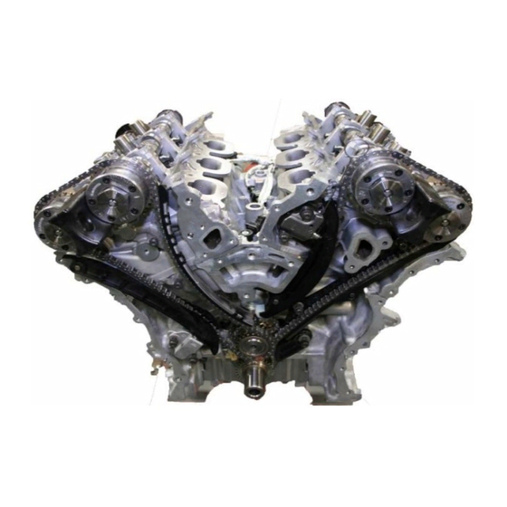
- Page 68 Long Block Assembly Revision DRAFT Section Timing Drive Description Mar‐16 Sheet The timing drive uses four silent chains. The silent chain link design improves sprocket engagement and reduces noise, vibration and harshness (NVH). One chain (5) drives the oil pump (4) and three chains drive the camshafts in a two stage design. The left secondary camshaft chain (1) uses an oil pressure controlled chain tensioner (9) with a ratcheting device. The right secondary camshaft chain (8) uses an oil pressure controlled tensioner (7) without a ratchet. The primary chain (2) also uses an oil pressure controlled tensioner (6) without a ratchet. A spring loaded tensioner (3) takes up the slack in the oil pump chain (5). The chain guides and tensioner arms are made of glass filled nylon with nylon wear faces 05184352AF Chain, Timing, Secondary 05184355AF Chain, Timing, Primary 3. 05184093AE Tensioner, Chain, Oil Pump 4. 68252670AA Pump, Engine Oil, Kit 5. 05184278AD Chain, Oil Pump, Drive 6. 05184391AF Tensioner, Chain, Primary 7. 05184888AC Tensioner, Chain, Primary, Right Side 8. 05184352AF Chain, Timing, Secondary 9. 05184360AF Tensioner, Chain, Primary, Left Side...
- Page 69 Long Block Assembly Revision DRAFT Section Timing Chain Assembly Mar‐16 Sheet Resetting the left side chain tensioner The slot (2) in the rack provides an anchor point for a pin that holds the rack in the retracted position. 1 Using a suitable tool, such as an allen wrench (1), lift the pawl off of the rack. 2 While holding the pawl off of the rack, push the rack and the piston into the tensioner body. 3 When the slot is aligned with the hole in the tensioner body, insert Tensioner Pin 8514 (1) to hold the rack and piston in the retracted position. Installing the camshaft phaser locks 1 Rotate the crankshaft counter clockwise to a position 30° before‐top‐dead‐center. View A Note: It may be necessary to rock the camshaft slightly (a few degrees) with a wrench (4) when installing the camshaft phaser locks. 2 Install the right side phaser lock 10202‐1 with the tool number facing up. 3 Install the left side phaser lock 10202‐ 2 with the tool number facing up. 4 Rotate the crankshaft clockwise back to top‐dead‐center after installing the camshaft phaser locks (2) the camshaft phaser locks (2) shown in View A. Right Side Left Side 10202 ‐ 1 10202 ‐ 2...
- Page 70 Long Block Assembly Revision 1 Section Primary Chain Assembly Jun‐18 Sheet 1 Place the primary chain onto the crankshaft sprocket (3) so that the arrow (2) is aligned with the plated link (1) on the timing chain. View from back side 2 While maintaining this alignment, invert the crankshaft sprocket and timing chain and place the idler sprocket (4) into the timing chain so that the dimple (2) is aligned with the plated link (1) on the timing chain. 3 While maintaining this alignment, lubricate the idler sprocket bushing with EF411 and install the sprockets and timing chain on the engine. To verify that the timing is still correct, the timing chain plated link (6) should be located at 12:00 (1) when the dimple (5) on the crankshaft is aligned with the block/bearing cap junction (4). 4 Install the idler sprocket retaining bolt (2) and washer (3). Tighten the T45 bolt (2) to 25 N∙m (18 ft. lbs.).
- Page 71 Long Block Assembly Revision DRAFT Section Primary Chain / Guides Mar‐16 Sheet 5 Install the primary chain guide (2). Tighten attaching T30 bolt (1) to 12 N∙m (106 in. lbs.). 6 Reset the primary chain tensioner (5) by pushing back the tensioner piston and installing Tensioner Pin 8514 (3). 7 Install the primary chain tensioner (5) to the engine block with two bolts (4). Tighten the T30 bolts (4) to 12 N∙m (106 in. lbs.) and remove the Tensioner Pin 8514 (3). 8 Install the right side cam chain guide (1) and tensioner arm (6). Tighten attaching T30 bolts (2) to 12 N∙m (106 in. lbs.). 9 Install the right side cam chain tensioner (3) to the engine block with two bolts (4). Tighten the T30 bolts (4) to 12 N∙m (106 in. lbs.). 10 Reset the right side cam chain tensioner (3) by pushing back the tensioner piston and installing Tensioner Pin 8514 (5). 11 Install the left side cam chain guide (2) and tensioner arm (1). Tighten attaching T30 bolts (4) to 12 N∙m (106 in. lbs.). 12 Install the left side cam chain tensioner (5) to the cylinder head with two bolts (6). Tighten the T30 bolts (6) to 12 N∙m (106 in. lbs.). 13 Reset the left side cam chain tensioner (5) by lifting the pawl (3), pushing back the piston and installing Tensioner Pin 8514 (7)
- Page 72 Long Block Assembly Revision DRAFT Section Timing Chain Assembly Mar‐16 Sheet 1 Drape the left side cam chain over the left side intake cam phaser and onto the idler sprocket (1) so that the arrow (3) is aligned with the plated link (2) on the cam chain. 2 While maintaining this alignment, route the cam chain around the exhaust and intake cam phasers so that the plated links are aligned with the phaser timing marks (1). Position the left side cam phasers so that the arrows (3) point toward each other and are parallel to the cylinder head cover mounting surface (5). Press the exhaust cam phaser onto the exhaust cam, install and hand tighten the oil control valve (2). 3 Drape the right side cam chain over the right side exhaust cam phaser and onto the idler sprocket (1) so that the dimple (2) is aligned with the plated link (3) on the cam chain.
- Page 73 Long Block Assembly Revision DRAFT Section Timing Chain Assembly Mar‐16 Sheet 4 While maintaining this alignment, route the cam chain around the exhaust and intake cam phasers so that the plated links are aligned with the phaser timing marks (1). Position the right side cam phasers so that the arrows (3) point away from each other and the scribe lines (4) are parallel to the cylinder head cover mounting surface (6). Press the intake cam phaser onto the intake cam, install and hand tighten the oil control valve (2). 5 Tighten all four oil control valves to 150 N∙m (110 ft. lbs.). Do Not Tighten Oil Control Valves without Phaser Locks in position. 6 Remove all phaser locks and tensioner lock pins.
- Page 74 Long Block Assembly Revision DRAFT Section Windage Tray / Oil Pump Mar‐16 Sheet Note: Lubricate the windage tray / main cap fasteners with EF‐411 as directed in Sections 4 and 7 prior to installation 1 Install the windage tray with eight main bearing cap bolts. Tighten the bolts in the sequence shown to 21 N∙m (16 ft. lbs.) plus 90°. 2 Align the locator pins (2) to the engine block and install the oil pump (3) with four bolts (1). Tighten the bolts to 12N∙m (106 in. lbs.). 3 Install the oil pump chain tensioner on the oil pump. 4 Position the oil pump chain tensioner spring (1) above the dowel pin (2). 5 Push back the oil pump chain tensioner and insert a suitable retaining pin (3) such as a 3 mm Allen wrench. 6 Place the oil pump sprocket (4) into the oil pump chain (3). Align the oil pump sprocket with the oil pump shaft and install the sprocket. Install the T45 retaining bolt (2) and tighten to 25 N∙m (18 ft. lbs.). 7 Remove the retaining pin (1). Verify that the oil pump chain is centered on the tensioner and crankshaft sprocket. 8 Rotate the crankshaft CW one complete revolution to verify proper oil pump chain installation.
- Page 75 Section 9 Final Dress...
- Page 76 Final Dress Revision DRAFT Section RTV Sealant Mar‐16 Sheet CAUTION: Do not use oil based liquids, wire brushes, abrasive wheels or metal scrapers to clean the engine gasket surfaces. Use only isopropyl (rubbing) alcohol, along with plastic or wooden scrapers. Improper gasket surface preparation may result in engine fluid leakage. CAUTION: Engine assembly requires the use of a unique sealant that is compatible with engine oil. Using a sealant other than Mopar Threebond Engine RTV Sealant may result in engine fluid leakage. CAUTION: Following the application of Mopar Threebond Engine RTV Sealant to the gasket surfaces, the components must be assembled within 20 minutes and the attaching fasteners must be tightened to specification within within 45 minutes. Prolonged exposure to the air prior to assembly may result in engine fluid leakage. 68082860AA Mopar RTV Sealant...
- Page 77 Final Dress Revision DRAFT Section Front Cover Mar‐16 Sheet 1 Remove all residual sealant from the timing chain cover, cylinder head and engine block mating surfaces (1), (2), (3), & (4). 2 Inspect the coolant outlet housing gasket (1) and the water pump gasket (2). Replace if necessary.
- Page 78 Final Dress Revision 1 Section Front Cover Jun‐18 Sheet 1 Clean the engine timing cover, cylinder head and block mating surfaces in preparation for sealant application. Isopropyl alcohol has been found suitable. 2 Apply a 2 to 3 mm wide bead of Mopar Threebond Engine RTV Sealant to the front cover as shown in the following locations: • Three cylinder head bosses (1) • Right and left flanges (2) • Four cylinder head to engine block T‐joints (3) • Cover to right cam chain tensioner gap (4)
- Page 79 Final Dress Revision 1 Section Front Cover Jun‐18 Sheet 1 Align the locator pins (5) on the engine block to the engine timing cover and install the cover. 2 Install twenty‐two M6 bolts (3) and one M8 bolt (4). Tighten the M6 bolts (3) to 11 N∙m (106 in. lbs.) and the M8 bolt (4) to 25 N∙m (18 ft. lbs.). Install three M10 bolts (1) to 55 N∙m (40 ft. lbs.) 3 Install the front balancer M16 bolt to 40 N∙m + 105˚ OHT3H‐302‐1 CROSSOVER, COOLANT OHT3H‐303‐1 CONNECTOR, COOLANT CROSSOVER OHT3H‐300‐1 PUMP, WATER, MODIFIED OHT3H‐304‐2 PAN, OIL MODIFIED, ASSY. (Upper, Lower, Dipstick)
- Page 80 Final Dress Revision DRAFT Section Upper Oil Pan Mar‐16 Sheet 1 Clean all sealing areas of the engine block and front and rear covers in preparation for the upper oil pan installation. 2 Apply a 2 to 3 mm wide bead of Mopar Threebond Engine RTV Sealant to the joints between the engine block and the front and rear covers. 3 Install 3H304‐19 Upper Oil Pan Gasket to engine. RTV Sealant (4) places 3H304‐19 Upper Oil Pan Gasket Note: Gasket view in photo is 180° rotated from view of engine...
- Page 81 Final Dress Revision DRAFT Section Upper Oil Pan Mar‐16 Sheet CAUTION: Make sure that the rear face of the oil pan is flush to the transmission bell housing before tightening any of the oil pan mounting bolts. A gap between the oil pan and the rear mount could crack the oil pan casting. 1 Install the oil pan to the engine block flush to the transmission bell housing. Secure the oil pan to the engine block with nineteen M8 oil pan mounting bolts (1) finger tight. 2 Tighten the nineteen previously installed M8 oil pan mounting bolts to 25 N∙m (18 ft. lbs.). View is shown with transmission attached in vehicle 3 Install the two M6 bolts (1) to the rear oil seal retainer flange and tighten to 12 N∙m (9 ft. lbs.).
- Page 82 Final Dress Revision 1 Section Lower Oil Pan Jun‐18 Sheet 1 Clean the upper and lower oil pan mating surfaces in preparation of installation of the lower oil pan. 2 Install 3H304‐18 lower oil pan gasket, 3 Install the lower oil pan to the upper oil pan with fifteen bolts (1) and tighten to 11 N∙m (97 in. lbs.).
- Page 83 Final Dress Revision 1 Section Camshaft Covers Jun‐18 Sheet CAUTION: Do not use oil based liquids, wire brushes, abrasive wheels or metal scrapers to clean the engine gasket surfaces. Isopropyl (rubbing) alcohol, along with plastic or wooden scrapers have been found suitable. Improper gasket surface preparation may result in engine fluid leakage. CAUTION: The magnetic timing wheels (1) must not come in contact with magnets (pickup tools, trays, etc.) or any other strong magnetic field. This will destroy the timing wheels ability to correctly relay camshaft position to the camshaft position sensor. 1 Remove all residual sealant (1) from the cylinder head, timing chain cover and cylinder head cover mating surfaces 2 Apply a 2 to 3 mm wide bead of Mopar Threebond Engine RTV Sealant (1) to the two engine timing cover to cylinder head T‐joints as shown. 3 Align the locator pins (1) to the cylinder head and install the cylinder head cover. 4 Tighten the cylinder head cover bolts and double ended studs in the sequence shown to 12 N∙m (106 in. lbs.).
- Page 84 Final Dress Revision DRAFT Section PCV Valve Mar‐16 Sheet The Crankcase Ventilation Valve must be modified for test. Using a M12 1.75 Tap threaded into the bushing about 4 threads, that holds the Valve, Spring, and Washer inside the PCV Housing. Clamp the tap into a vise and lightly tap on the housing with a plastic mallet to pull the bushing out and remove the insides. 1 Install the empty PCV Housing (1) in the rear of the right camshaft cover aligning the inner lip seal with the right side exhaust camshaft and fasten using the three fasteners (2) ...
- Page 85 Final Dress Revision DRAFT Section Cam Sensors / Coils Mar‐16 Sheet 1 Install both the left and right camshaft position sensors. NOTE: Spark Plugs and Ignition Coils may be installed at the test stand. 2 Install the spark plugs and ignition coils. 3 If removed, Install the variable valve timing solenoids.
- Page 86 Final Dress Revision DRAFT Section Oil Cooler Mar‐16 Sheet Note: Ensure proper main oil gallery thermocouple is installed before installing oil filter assembly See Section 7 Sheet 5 for direction 1 Install the O‐ring seals for the oil cooler to the oil filter / cooler housing. (Non Serviced Parts) 2 Assembly cleaned oil cooler to housing using six (6) Torx Head Screws torqued to 12 N∙m (106 in. lbs.) 3 Lightly lubricate the O‐ring on a new oil filter element with EF‐411 and install the element into the oil filter housing. 4 Lightly lubricate the O‐ring for the oil filter element cap with EF‐411 and install on the oil filter housing. 5 Install new oil filter housing seals (1)&(2) onto the oil filter housing. 68191356AA Kit, O‐Ring, Oil filter Housing (5 pc.) items (1) & (2) in view 6 Position the oil filter housing (1) on the engine block. 7 Install five bolts and tighten in the sequence shown to 12 N∙m (106 in. lbs.). Note: Labs must install the oil filter and charge the engine with test oil before starting engine. Note: Oil Filter must be 2014 or newer to seal properly in adapter housing. 04893383AB Filter, Oil 68191349AB Filter, Oil, with O‐Ring...
- Page 87 Final Dress Revision DRAFT Section Lower Intake Mar‐16 Sheet Note: Ensure proper main oil gallery thermocouple is installed before installing lower intake assembly See Section 7 Sheet 5 for direction 1 Check the lower intake manifold assembly to ensure the fuel rail and injectors are installed and the seals are all in tact and clean. Ensure there are no debris inside the inlet ports on the cylinder heads and lower intake assembly. 2 Position the lower intake manifold (1) on the cylinder head surfaces 3 Install the manifold attaching bolts and tighten in the sequence shown to 8 N∙m (71 in. lbs.). 4 Cover the inlet ports with tape or install the upper intake assembly depending on lab practices. 5 Install the upper intake manifold (1), support brackets and resonator leaving the insolated pad out ( the insolated pad for NVH is not used in testing). CAUTION: The upper intake manifold fasteners are screw type and self thread into the lower intake. Operators and build technicians must exercise care during tightening. If the fasteners are striped, a new lower intake must be used.
-
Page 88: Crankcase Ventilation
Revision DRAFT Section Crankcase Ventilation Mar‐16 Sheet Crankcase Ventilation Set‐up views... - Page 89 Section 10 OHT Hardware...
- Page 90 3H304-03 PLUG, OIL, DRAIN, SEQ. IIIH 3H304-11 DISPTICK, ASSEMBLY, SEQ. IIIH 3H304-18 GASKET, LOWER, PAN, OIL, IIIH (REV. A), SEQ. IIIH 3H304-19 GASKET, UPPER, PAN, OIL, SEQ. IIIH OHT3H-001-1 PENTASTAR INTAKE PHASER (FIXED AT 110°, LESS HOLES DRILLED IN ROTOR) OHT3H-002-1 PENTASTAR EXHUAST PHASER (FIXED AT 112°, LESS HOLES...
- Page 91 Revision DRAFT Section OH Technologies Mar‐16 Sheet OHT3H‐300‐1 Pump, Water, Modified OHT3H‐302‐1 Crossover, Coolant...
- Page 92 Revision DRAFT Section OH Technologies Mar‐16 Sheet OHT3H‐303‐1 RevisionB ‐ Adapter, Coolant Crossover with Couplings Comes as an assembly ‐ items 1 ‐ 6...
- Page 93 Revision DRAFT Section OH Technologies Mar‐16 Sheet OHT3H‐304‐2 Pan, Oil, Modified...
- Page 94 Revision DRAFT Section OH Technologies Mar‐16 Sheet OHT3H‐304‐19 Gasket, Pan, Oil, Upper OHT3H‐304‐18 Gasket, Pan, Oil, Lower...
- Page 95 Revision DRAFT Section OH Technologies Mar‐16 Sheet OHT3H‐070‐1 Piston, IIIH, Special OHT3H‐96040‐1 RINGS, SPECIAL TEST, ENGINE SET (SEQ. IIIH) Second Rail Expander...
- Page 96 Section 11 Reagents and Equipment...
- Page 97 Chrysler Sequence IIIH Oxidation & Deposit Test Reagents Engine Assembly Lubricant: EF-411, Engine Assembly Lubricant, supplied through ExxonMobil Engine Coolant: ShellZone Dex-Cool® Extended Life antifreeze/coolant concentrate (product code 94040) ShellZone Dex-Cool Extended Life antifreeze/coolant premix which is a mixture of ShellZone Dex-Cool antifreeze/coolant and deionized water (product code 94070).
- Page 98 50 mm Extension 12AAG202 BHJ: Cylinder Block Honing Torque Plates, MP-3.6PSV6-R-AL-T-DID IMTS: Chrysler IIIH Thermocouple Tapping Fixture Assembly 151132-F001 Tierra Tech Ultra Sonic Parts Cleaner: Tierra Tech MOT-500NS Ultra Sonic Cleaner, (or equivalent model) Starrett: ...
- Page 99 IIIH Engine Assembly Manual Section 12 Document Update Timeline Revision March 2016 Section Sheet Action Description 1 1 Delete Piston clearance specification from text 3 1 Delete Reference to retaining vent tube for later use 3 9 Addition Add removal of timing chain idler shaft & valve shims 3 10 Addition Additional note on timing chain idler shaft removal 4 All Section 4 Honing Complete Re‐write outlining Engine Builder Workshop updated Honing Guidelines. 5 1 Addition Cleaning clarification, wiping cylinders with EF‐411 7 5 Delete Removal of main oil gallery front cup plug 7 5 ...
- Page 100 4 9 Change 17. Set Zero Cut Off Mode to “ON” with the Auto Finish “OFF”. 4 10 Change 28. Set the Auto Finish to “ON”. 4 11 Change Revised Surface Finish limits 4 12 Addition “Wipe the cylinder bores and piston rings with solvent prior to performing ring gaps. Ensure the piston rings are clean and all paint marks are removed.” 5 1 Change Change ultrasonic cleaning solutions to Brulin GD and Brulin QR‐DF” 5 2 Change Torque for oil pump shield fasteners 8 2 Change Corrected typo Debris such as RTV sealants, coolant, engine oil, or cleaning solvents can cause hydraulic locking and aluminum castings to crank crack when tightening cylinder head fasteners 8 10 Change While maintaining this alignment lubricate the idler sprocket bushing with EF‐411 clean engine oil and install the sprockets and timing chain on the engine 9 3 Change ...
Need help?
Do you have a question about the IIIH and is the answer not in the manual?
Questions and answers