
Related Manuals for ZPA Pečky MODACT MOKA 63


Summary of Contents for ZPA Pečky MODACT MOKA 63
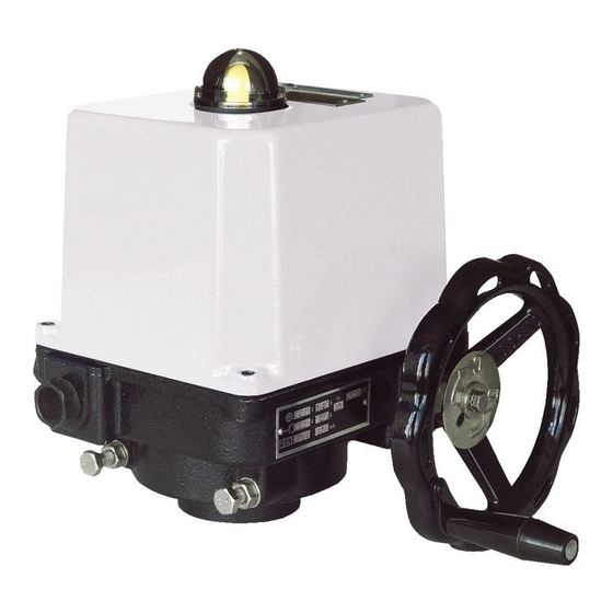
- Page 1 E le ctr ic ro tar y (90°) actu ators for b all valves a n d flap s - outside containment of nuclear power plants with reactors VVER and RBMK Type num b ers 52 325 - 52 32 9 12/15...
- Page 3 USING Actuators MODACT MOKA manufactured in compliance with technical conditions 32-03/07 are intended for controlling shut-off and regulating valves, including valves of protective systems installed in the non- sealed part of nuclear power plants with reactors of type VVER and in attended rooms of nuclear power plants with reactors of type RBMK.
- Page 4 Course of working cycle Mean value of moment Maximum tripping moment Starting moment Time of operation Idle time Time of working cycle Time BASIC TECHNICAL DATA Service life of actuators. Reliability Service life of the actuators is min. 40 years. The actuators belong to the category of restoring products of standardized reliability.
- Page 5 The actuators of protective systems must be operational under the following conditions: – Voltage decreased to 80 % of its rated value with simultaneously decreased frequency by 6 % of its rated value for 15 s; – Voltage increased to 110 % of its rated value with simultaneously increased frequency by 3 % of its rated value during 15 s.
- Page 6 Active current position transmitter DCPT Rated output signal 4 – 20 mA or 20 – 4 mA Rated working run from 60° to 0 – 340°, regulated Loading resistance 0 – 500 ohm Non-linearity max. 1 % Supply voltage 18 – 28 V DC Dimensions ø...
- Page 7 Noise According to GOST P 51402-99, the value of mean level of acoustic pressure at a distance of 2 m (in no-load operation of actuators) does not exceed 80 dB. Run-out of output shaft Motors of type no. 52325, 52 326, 52 328 max.
- Page 8 The potentiometer is fitted with a slipping clutch to permit automatic adjustment along with the output shaft. The anti-condensation heater 8 (Fig.1, 2) prevents water vapours from condensing under the cover of the control section. The position-limit switching unit and the position transmitter derive their movements from the output shaft of the actuator via a driving gear (or in the actuators, Type Nos 52 326 and 52 327, via driving segment 7, as shown in Fig 1).
- Page 9 When setting the stop screws in the actuators, Type Nos 52 326 ant 52 327, care should be taken to ensure that, in the CLOSED or OPEN end position, the driving gear segment of the position-limit switching and auxiliary signalling units cannot strike the electric motor. In either end position of the output shaft of the actuator, the local position indicator should tally with the marks on the index plate.
- Page 10 52 326 and 52 327, ensure that a gear segment of position and signalling unit drive in the extreme position “open” or “closed” doesn’t hit the actuator case. A position unit of electric actuator Type No. 52 325 is not equipped with the locking of cams using screws (Fig.
- Page 11 Sensor position out of working range Working range incorrectly set Off the tolerance level of magnetic field Wrong parameters in EEPROM Wrong parameters in RAM 4. Calibration of currents 4 mA and 20 mA. On switching-on the power supply, keep the push-buttons “4” and “20” depressed and release them after a sin- gle blink of LED.
- Page 12 the opposite direction), it is necessary to reverse the sense of rotation of the actuator output shaft by interchanging two (of three) connected phase conductors U, V, W (e.g. the phase conductor connected to the terminal U should be reconnected to the terminal W and the conductor connected to the terminal W to the terminal U). Then, the check of the sense of rotation should be repeated.
- Page 13 GUARANTEE CONDITIONS The manufacturer guarantees compliance of the manufactured actuators and completing parts with requirements of TP 32-03/07, provided that the user observes the operating, transportation and storage conditions specified in TP. The guarantee period for the actuators is min. 36 months from the date of issuing the acknowledgement of delive- ry (or from the date of the border crossing –...
- Page 15 Table 2 – MODACT MOKA – way of mechanical connection (specification of 9th place of type number) Connection or square Type Number Flange size Square position Marking on the 9 place of type number size with [mm] keyway – x x x 0 A F 0 5 basic x x x 1 A keyway...
- Page 16 Dimensional sketch of MODACT MOKA electric actuators Local control M20x1,5 (1 0–14mm) Cable bushings: Local MOKA 63 M20x1,5 (10 – 14 mm) control M25x1,5 (13 – 18 mm) MOKA 125, 250 2x M25x1,5 (13 – 18 mm) MOKA 500, 1000 1x M25x1,5 (13 –...
- Page 17 Connection dimensions of MODACT MOKA actuators – for valves and control devices with spindles that are provided with a tight-fit keyway Position of the keyway, according to ISO 5211 and DIN 3337 (The groove is in the CLOSE position whereas the OPEN position is on the left side when viewing the local position indicator).
- Page 18 Connection dimensions of MODACT MOKA actuators – for valves and control devices with spindles that are provided with a square hole A – Square-end joint in the basic posistion B – Square-end joint positioned at an angle of 45° Position of the square hole in the end position of the actuator. The OPEN position is on the left of the CLOSE position, when viewing the local position indicator.
- Page 19 Wiring diagrams of MODACT MOKA electric actuators Design with potentiometer or without transmitter Design with pasive current position transmitter Control circuits Electric motor cable input cable input Design with active current position transmitter (with power source) Control circuits Electric motor cable input cable input...
- Page 20 Legend: SQFC1 (MO) – OPEN torque-limit switch – Anti-condensation heater SQFT1 (MZ) – CLOSE torque-limit switch – Anti-condensation heater SQC1 (PO) – OPEN position-limit switch CPT1AA – Current position transmitter CPT SQT1 (PZ) – CLOSE position-limit switch – Power supply of current position SQC2 (SO) –...
- Page 21 NOTES...
- Page 22 NOTES...
- Page 23 tel.: +420 321 785 141-9 ZPA Pečky, a.s. fax: +420 321 785 165 tř. 5. května 166 +420 321 785 167 289 11 PEČKY, Czech Republic e-mail: zpa@zpa-pecky.cz www.zpa-pecky.cz...
- Page 24 Development, production and services of electric actuators and switchboards. Top-quality sheet-metal processing (TRUMPF equipment), powder paint shop. SURVEY OF PRODUCED ACTUATORS KP MINI, KP MIDI Electric rotary (90°) actuators (up to 30 Nm) MODACT MOK, MOKED, MOKP Ex Electric rotary (90°) actuators for ball valves and flaps MODACT MOKA Electric rotary (90°) actuators for nuclear power stations application outside containment...
Need help?
Do you have a question about the MODACT MOKA 63 and is the answer not in the manual?
Questions and answers