
Subscribe to Our Youtube Channel
Related Manuals for Metrohm 6.5330.110


Summary of Contents for Metrohm 6.5330.110
- Page 1 IC equipment IC equipment: Inline-Ultrafiltration (6.5330.110) Manual 8.110.8037EN / 2014-02-20...
- Page 3 Metrohm AG CH-9100 Herisau Switzerland Phone +41 71 353 85 85 Fax +41 71 353 89 01 info@metrohm.com www.metrohm.com IC equipment IC equipment: Inline-Ultrafiltration (6.5330.110) Manual 8.110.8037EN / 2014-02-20...
- Page 4 Technical Communication Metrohm AG CH-9100 Herisau techcom@metrohm.com This documentation is protected by copyright. All rights reserved. This documentation has been prepared with great care. However, errors can never be entirely ruled out. Please send comments regarding possible errors to the address above.
-
Page 5: Table Of Contents
■■■■■■■■■■■■■■■■■■■■■■ Table of contents Table of contents 1 Introduction Description of the IC equipment: Inline-Ultrafiltration ..1 About the documentation ........... 1 Symbols and conventions ............ 2 2 Overview Parts of the IC equipment: Inline-Ultrafiltration ....3 Components of the ultrafiltration cell ........ 3 Connectors of the ultrafiltration cell ........ - Page 6 ■■■■■■■■■■■■■■■■■■■■■■ Table of figures Table of figures Figure 1 IC equipment: Inline-Ultrafiltration – Parts .......... 3 Figure 2 Ultrafiltration cell – Parts ..............3 Figure 3 Ultrafiltration cell – Connectors ............4 Figure 4 Connecting the ultrafiltration cell ............. 10 ■■■■■■■■...
-
Page 7: Introduction
1 Introduction 1 Introduction Description of the IC equipment: Inline-Ultrafiltra- tion The IC equipment: Inline-Ultrafiltration (6.5330.110) contains all accesso- ries required for Inline Ultrafiltration of difficult samples directly before injection. The main component of the IC equipment: Inline-Ultrafiltration is the high- performance ultrafiltration cell. -
Page 8: Symbols And Conventions
■■■■■■■■■■■■■■■■■■■■■■ 1.3 Symbols and conventions Symbols and conventions The following symbols and formatting may appear in this documentation: Cross-reference to figure legend The first number refers to the figure number, the sec- ond to the instrument part in the figure. Instruction step Carry out these steps in the sequence shown. -
Page 9: Overview
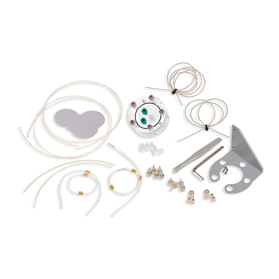
■■■■■■■■■■■■■■■■■■■■■■ 2 Overview 2 Overview Parts of the IC equipment: Inline-Ultrafiltration 6.1803.080 6.2729.110 6.1831.060 6.1831.160 6.2714.020 6.2831.010 6.2744.070 6.2057.030 6.1803.050 6.2744.030 6.2621.070 6.2744.000 6.2744.160 6.1826.390 6.1826.320 Figure 1 IC equipment: Inline-Ultrafiltration – Parts Components of the ultrafiltration cell Figure 2 Ultrafiltration cell –... -
Page 10: Connectors Of The Ultrafiltration Cell
■■■■■■■■■■■■■■■■■■■■■■ 2.3 Connectors of the ultrafiltration cell Sealing ring Lower chamber Washers Screws For joining the upper and the lower part of the cell. Connectors of the ultrafiltration cell Figure 3 Ultrafiltration cell – Connectors Upper chamber Lower chamber Filtrate outlet Sample inlet Labeled OUT. -
Page 11: Mode Of Operation For Ultrafiltration
■■■■■■■■■■■■■■■■■■■■■■ 2 Overview Mode of operation for ultrafiltration The peristaltic pump delivers a continuous flow of sample solution at a high rate through the lower chamber of the ultrafiltration cell. The sample flows along the filtration membrane and then to the waste container. At the same time, the peristaltic pump's second channel generates a vac- uum in the upper chamber of the ultrafiltration cell, thus pulling the sam- ple solution through the filtration membrane. -
Page 12: Installation
■■■■■■■■■■■■■■■■■■■■■■ 3.1 Preparing the ultrafiltration cell 3 Installation This chapter describes how to assemble the ultrafiltration cell, how to fas- ten the ultrafiltration cell to the Sample Processor or in the ion chromato- graph and how to connect the ultrafiltration cell to the peristaltic pump and the injection valve. - Page 13 ■■■■■■■■■■■■■■■■■■■■■■ 3 Installation Remove the 3 green stoppers. ■ Turn the ultrafiltration cell around and place it on a table. The ■ screws face upwards. 2 Removing the screws Loosen the screws with the hex key. ■ Remove the screws with the washers and put them aside. ■...
- Page 14 ■■■■■■■■■■■■■■■■■■■■■■ 3.1 Preparing the ultrafiltration cell Thoroughly rinse off the sealing ring, the upper chamber and the ■ lower chamber of the ultrafiltration cell with ultrapure water. Dry all parts with a lint-free cloth. ■ 5 Wetting the filtration membrane NOTICE In the package containing the filtration membranes, you will find sheets of different thicknesses and colors:...
- Page 15 ■■■■■■■■■■■■■■■■■■■■■■ 3 Installation Place the sealing ring back in the recess. ■ Using the tweezers, place the wet filtration membrane centrally ■ inside the sealing ring onto the cell. 7 Assembling the ultrafiltration cell Place the upper chamber of the ultrafiltration cell on the lower ■...
-
Page 16: Connecting The Ultrafiltration Cell
■■■■■■■■■■■■■■■■■■■■■■ 3.2 Connecting the ultrafiltration cell Connecting the ultrafiltration cell This chapter describes how to establish the capillary connections of the fil- tration system (regardless of whether the filtration cell is installed on the Sample Processor or in the ion chromatograph). It does not, however, describe the tubing configuration for the peristaltic pump. - Page 17 ■■■■■■■■■■■■■■■■■■■■■■ 3 Installation Coupling olive/UNF 10/32 (6.2744.030) ■ Pressure screw, short (6.2744.070) ■ Pump tubing connection with locking nut (6.2744.160) ■ 1 Preparing the pump tubing for the sample Use the pump tubing with yellow stoppers (6.1826.390) for convey- ing the sample. Attach the coupling olive/UNF 10/32 (6.2744.030) to the inlet.
- Page 18 ■■■■■■■■■■■■■■■■■■■■■■ 3.2 Connecting the ultrafiltration cell 4 Connecting the capillaries to the pump tubing for the filtrate Tighten the PTFE capillary (6.1803.050) to the inlet of the pump ■ tubing with orange/yellow stoppers (6.1826.320) using a pressure screw (6.2744.070). Tighten the PEEK capillary (6.1831.060) to the outlet of the pump ■...
-
Page 19: Inserting The Ultrafiltration Cell
■■■■■■■■■■■■■■■■■■■■■■ 3 Installation Tighten the PTFE capillary (6.1803.050) to the outlet labeled OUT ■ of the ultrafiltration cell's upper chamber using a PVDF pressure screw (6.2744.000). 6 Connecting the remaining capillaries Tighten the free end of the PEEK capillary (6.1831.160) to the ■... - Page 20 ■■■■■■■■■■■■■■■■■■■■■■ 3.3 Inserting the ultrafiltration cell Insert the ultrafiltration cell in such way that the screw heads are ■ located in the holes in the filtration cell holder provided for this purpose. Inserting the ultrafiltration cell in the ion chromatograph Required accessories Filtration cell holder (6.2057.140) ■...
-
Page 21: Deaerating The Ultrafiltration Cell
■■■■■■■■■■■■■■■■■■■■■■ 3 Installation Deaerating the ultrafiltration cell Every time a new filtration membrane is inserted, the air which may still be present in the filtration cell and in the capillaries must be removed. To accomplish this, rinse out all capillaries with e.g. ultrapure water. NOTICE The entire filtration system must be completely connected prior to the rinsing procedure. - Page 22 ■■■■■■■■■■■■■■■■■■■■■■ 3.4 Deaerating the ultrafiltration cell Check whether any air bubbles remain trapped in the ultrafiltra- ■ tion cell. If air bubbles are trapped in the cell, then unscrew the PTFE capil- laries from the filtrate outlet (3-3) and from the sample outlet (3-5) and wait until the air bubbles have escaped.
-
Page 23: Operation And Maintenance
The following table lists some sample types that were filtered with the ultrafiltration cell (6.2729.110) and a filtration membrane (6.2714.020) with a pore size of 0.2 µm and subsequently analyzed on a Metrohm ion chromatograph. The concentration of the following seven anions was –... -
Page 24: Selecting The Filtration Membrane
Aqueous earth extracts 4.1.2 Selecting the filtration membrane You can apply existing sample preparation procedures to the Metrohm ultrafiltration cell (6.2729.110). If you wish to use a different filtration membrane than the one supplied, please note that, even if the particle size is known, selecting a membrane with a suitable pore size does not automatically yield the desired results. -
Page 25: Maintenance
■■■■■■■■■■■■■■■■■■■■■■ 4 Operation and maintenance Nominal pore size according to manufacturer's statement. Except for this membrane, all membranes were from the same manufac- turer. Please also note that because of the lower filter thickness the retention capacity of filtration membranes may be lower than that of filters with the same pore size but a higher filter thickness. - Page 26 ■■■■■■■■■■■■■■■■■■■■■■ 4.2 Maintenance Tighten the PTFE capillary (6.1803.060) to the inlet labeled IN of ■ the ultrafiltration cell's lower chamber using a PVDF pressure screw (6.2744.000). Tighten the PTFE capillary (6.1803.080) to the outlet labeled OUT ■ of the ultrafiltration cell's lower chamber using a PVDF pressure screw (6.2744.000).
-
Page 27: Technical Specifications
■■■■■■■■■■■■■■■■■■■■■■ 5 Technical specifications 5 Technical specifications Ultrafiltration cell (6.2729.110) Material PMMA (poly(methyl methacrylate)) Solvent compati- Water or water-ethanol mixture (70:30) bility (no other organic solvents) Cell volume 240 µL (each from inlet to outlet opening) Filtration membrane (6.2714.020) Pore diameter 0.2 µm Membrane diame- 47 mm... -
Page 28: Accessories
Downloading the accessories list 1 Enter https://www.metrohm.com/ into your Internet browser. 2 Enter the article number (e.g. 6.5330.110) into the search field. The search result is displayed. 3 Click on the product. Detailed information regarding the product is shown on various tabs. - Page 29 ■■■■■■■■■■■■■■■■■■■■■■ Index Index Capillary connections ....10 Maintenance ......19 Technical specifications ..... 21 Mounting Filtration membrane ..... 6 Deaerate Ultrafiltration Ultrafiltration cell ....15 Mode of operation ....5 Operation ......... 17 Ultrafiltration cell Components ......3 Filtration membrane Connect ......
Need help?
Do you have a question about the 6.5330.110 and is the answer not in the manual?
Questions and answers