
Subscribe to Our Youtube Channel
Related Manuals for Metrohm Dialysis 6.5330.100


Summary of Contents for Metrohm Dialysis 6.5330.100
- Page 1 IC equipment Dialysis 6.5330.100 | Dialysis Low Volume 6.5330.200 Manual 8.110.8028EN / 2018-09-07...
- Page 3 Metrohm AG CH-9100 Herisau Switzerland Phone +41 71 353 85 85 Fax +41 71 353 89 01 info@metrohm.com www.metrohm.com IC equipment Dialysis 6.5330.100 | Dialysis Low Volume 6.5330.200 Manual 8.110.8028EN / 2018-09-07 ksah...
- Page 4 Technical Communication Metrohm AG CH-9100 Herisau techcom@metrohm.com This documentation is protected by copyright. All rights reserved. This documentation has been prepared with great care. However, errors can never be entirely ruled out. Please send comments regarding possible errors to the address above.
-
Page 5: Table Of Contents
Recommended procedure for the dialysis ....... 21 Maintenance ............... 23 5 Technical specifications Dialysis cell (6.2729.100) ........... 25 Low Volume dialysis cell (6.2729.200) ......25 Dialysis membrane (6.2714.010) ........25 Dialysis membrane (6.2714.030) ........25 6 Accessories Index ■■■■■■■■ IC equipment Dialysis 6.5330.100... - Page 6 IC equipment: Dialysis | Dialysis Low Volume – Parts ......4 Figure 2 Dialysis cell – Parts ................5 Figure 3 Dialysis cell – Connectors ..............6 Figure 4 Stopped-flow dialysis ................. 7 Figure 5 Area / transfer time diagram ............20 ■■■■■■■■ IC equipment Dialysis 6.5330.100...
-
Page 7: Introduction
1 Introduction Description of IC equipment: Dialysis | Dialysis Low Volume The IC equipment: Dialysis 6.5330.100 | Dialysis Low Volume 6.5330.200 contains all accessory parts required for Inline Dialysis of matrix-contami- nated samples (e.g. emulsions, samples containing fat and protein, body fluids or waste waters with high pollution loads) directly before injection. -
Page 8: About The Documentation
Menu or menu item [Next] Button or key WARNING This symbol draws attention to a possible life-threat- ening hazard or risk of injury. WARNING This symbol draws attention to a possible hazard due to electrical current. ■■■■■■■■ IC equipment Dialysis 6.5330.100... - Page 9 WARNING This symbol draws attention to a possible biological hazard. CAUTION This symbol draws attention to possible damage to instruments or instrument parts. NOTE This symbol highlights additional information and tips. ■■■■■■■■ IC equipment Dialysis 6.5330.100...
-
Page 10: Overview
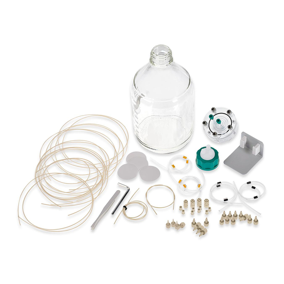
2 Overview Parts of the IC equipment: Dialysis | Dialysis Low Volume Figure 1 IC equipment: Dialysis | Dialysis Low Volume – Parts Parts of IC equipment: Dialysis Parts of IC equipment: Dialysis Low Volume ■■■■■■■■ IC equipment Dialysis 6.5330.100... -
Page 11: Parts Of The Dialysis Cell
■■■■■■■■■■■■■■■■■■■■■■ 2 Overview Parts of the dialysis cell Figure 2 Dialysis cell – Parts Stopper Donor chamber Sealing ring Acceptor chamber Washers Screws For joining the acceptor and the donor chamber. ■■■■■■■■ IC equipment Dialysis 6.5330.100... -
Page 12: Dialysis Cell Connectors
Dialysis cell – Connectors Donor chamber Acceptor chamber Outlet – Sample Inlet – Sample Inlet – Acceptor solution Outlet – Acceptor solution NOTICE The product number (6.2729.200) is only engraved in the Low Volume dialysis cell. ■■■■■■■■ IC equipment Dialysis 6.5330.100... -
Page 13: Mode Of Operation For Dialysis
The concentration in the acceptor solution thus matches the concentration of the original sample. Afterwards, the acceptor solution is injected directly into the ion chromatograph. ■■■■■■■■ IC equipment Dialysis 6.5330.100... -
Page 14: Installation
Dialysis membrane (6.2714.010) ■ Hex key (6.2621.070) ■ Tweezers (6.2831.010) ■ 1 Removing the stoppers Remove the four green stoppers. ■ Turn the dialysis cell around and place it on a table. ■ The screws face upwards. ■■■■■■■■ IC equipment Dialysis 6.5330.100... - Page 15 Use only ultrapure water or a water-ethanol mixture (70:30) for ■ cleaning the dialysis cell. For samples that contain organic components (e.g. solvents), ■ use the PEEK dialysis cell (6.2729.120). This cell has an excellent chemical resistance to organic chemicals. ■■■■■■■■ IC equipment Dialysis 6.5330.100...
- Page 16 6 Inserting the dialysis membrane NOTICE Make sure that the water-soaked dialysis membrane does not dry out before it is inserted, as it can otherwise no longer be used. ■■■■■■■■ IC equipment Dialysis 6.5330.100...
- Page 17 8 Screwing the dialysis cell together Screw the five screws with the washers in the dialysis cell by hand ■ first. Then firmly tighten them with the hex key in crosswise sequence. ■ ■■■■■■■■ IC equipment Dialysis 6.5330.100...
-
Page 18: Connecting The Dialysis Cell
Pump tubing LFL (orange/yellow), 3 stoppers (6.1826.320) ■ Pump tubing LFL (black/black), 3 stoppers (6.1826.340) ■ PEEK capillary ■ – 0.5 mm ID / 40 cm (6.1831.050)* – 0.25 mm ID / 45 cm (6.1831.120)** ■■■■■■■■ IC equipment Dialysis 6.5330.100... - Page 19 Attach the pump tubing connection with locking nut ■ (6.2744.160) to the outlet (see chapter "Installing the peristaltic pump" in the manual for the ion chromatograph or in the man- ual for the Sample Processor). ■■■■■■■■ IC equipment Dialysis 6.5330.100...
- Page 20 (3-3) using a pressure screw (6.2744.000). Tighten the other end of the PTFE capillary to the inlet of the sec- ond pump tubing with black stoppers (6.1826.340) using a pres- sure screw (6.2744.070). ■■■■■■■■ IC equipment Dialysis 6.5330.100...
- Page 21 (6.2744.070). Tighten the other end of the PTFE capillary to the acceptor inlet of the dialysis cell (3-5) using a pressure screw (6.2744.000). 6 Connecting the outlet of the acceptor solution ■■■■■■■■ IC equipment Dialysis 6.5330.100...
-
Page 22: Inserting The Dialysis Cell
Tighten the other end of the PTFE capillary to the waste container. Inserting the dialysis cell Inserting the dialysis cell into the ion chromatograph Insert the dialysis cell into the cell holder provided for this pur- ■ pose. ■■■■■■■■ IC equipment Dialysis 6.5330.100... - Page 23 (6.2057.120) can be used. Insert the dialysis cell into the dialysis cell holder (6.2057.120). ■ Insert the dialysis cell with the dialysis cell holder into the detector ■ chamber of the ion chromatograph. ■■■■■■■■ IC equipment Dialysis 6.5330.100...
-
Page 24: Conditioning The Dialysis System
If air bubbles are trapped in the cell, then unscrew the PEEK capil- lary and the PTFE capillary, (3-3) and (3-6), from the outlets of the dialysis cell and wait until the air bubbles have escaped. After- wards, tighten the capillaries to the dialysis cell again. ■■■■■■■■ IC equipment Dialysis 6.5330.100... -
Page 25: Operation And Maintenance
2 Additional measurements Increase the transfer time in the software by 5 s each time and ■ start the determination. Repeat the measurements until the measured area starts to ■ decrease again. ■■■■■■■■ IC equipment Dialysis 6.5330.100... -
Page 26: Figure 5 Area / Transfer Time Diagram
(6.2714.010) (Cellulose acetate; thickness = 115 µm; pore size = 0.2 µm) and a total ion concentration of ≥ 5 mg/L in the sample, the guideline value for the dialysis time is 6 minutes. This guideline value must be verified for each installation. ■■■■■■■■ IC equipment Dialysis 6.5330.100... -
Page 27: Recommended Procedure For The Dialysis
Carrying out a dialysis 1 Preparing the acceptor solution To avoid disruptions caused by air bubbles in the acceptor flow, ■ degas the ultrapure water used as acceptor solution for at least 10 minutes. ■■■■■■■■ IC equipment Dialysis 6.5330.100... - Page 28 Switch on the peristaltic pump for the sample channel in the soft- ■ ware. Rinse the dialysis system with the acceptor solution and the rins- ■ ing solution for approx. 10 minutes and then switch off the peri- staltic pumps again. ■■■■■■■■ IC equipment Dialysis 6.5330.100...
-
Page 29: Maintenance
Tighten the sample inlet capillary to the dialysis cell inlet for the ■ sample (3-4) using a PVDF pressure screw (6.2744.000). Tighten the sample outlet capillary to the dialysis cell outlet for ■ the sample (3-3) using a PVDF pressure screw (6.2744.000). ■■■■■■■■ IC equipment Dialysis 6.5330.100... - Page 30 (3-5) using a PVDF pressure screw (6.2744.000). Tighten the acceptor outlet capillary to the dialysis cell outlet for ■ the acceptor solution (3-6) using a PVDF pressure screw (6.2744.000). 4 Conditioning the dialysis system (see chapter 3.4, page 18). ■■■■■■■■ IC equipment Dialysis 6.5330.100...
-
Page 31: Technical Specifications
Water or water-ethanol mixture (70:30) bility (no other organic solvents) Dialysis membrane (6.2714.010) Pore diameter 0.20 µm Membrane diame- 47 mm Material Cellulose acetate Dialysis membrane (6.2714.030) Pore diameter 0.15 µm Membrane diame- 47 mm Material Polyamide ■■■■■■■■ IC equipment Dialysis 6.5330.100... -
Page 32: Accessories
The PDF file with the accessories data is created. NOTICE When you receive your new product, we recommend downloading the accessories list from the Internet, printing it out and keeping it together with the manual for reference purposes. ■■■■■■■■ IC equipment Dialysis 6.5330.100... -
Page 33: Index
Optimize ......19 Maintenance ......23 Transfer time Dialysis cell Determine ......19 Connectors ......6 Operation ......... 19 Parts ........5 Operation and maintenance ..19 Prepare ......... 8 Dialysis system Condition ......18 ■■■■■■■■ IC equipment Dialysis 6.5330.100...
Need help?
Do you have a question about the Dialysis 6.5330.100 and is the answer not in the manual?
Questions and answers