Advertisement
Quick Links
Models:
ISS01 – innTOUCH Smart Sensor
ISS02 – innTOUCH Smart Sensor with Real Time Clock (RTC)
ISS03 – innTOUCH Smart Sensor with Universal Inputs (UI)
ISS04 – innTOUCH Smart Sensor with RTC and UI
Overview
The Innotech innTOUCH Smart Sensor is a wall mounted remote
Human Machine Interface (HMI) panel that provides a user interface
for supported Innotech MiniMAX, VAVMax, MicroMAX, Omni C20x and
Omni C40x controllers.
The innTOUCH Smart Sensor has a single communications channel,
with data transfer occurring through the power supply interface.
Power and communication are provided through the 2-way
Combicon connector.
One innTOUCH Smart Sensor can interface with a supported
controller. All data points on the innTOUCH Smart Sensor are
updated at the same rate as the controllers.
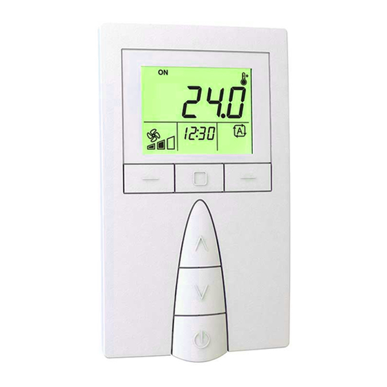
Features
• Icon based backlit Liquid Crystal Display (LCD)
• Modern, attractive enclosure design
• Four universal inputs (optional)
• One integrated thermistor input
• Real Time Clock (optional)
• Push button interface
• Direct interface with the MM01C, MM02C, VM01C, UM01C, OMC20,
OMC20D, OMC40 and OMC40D controllers
• Two wire single twisted pair, shielded or unshielded connection
from controller provides both comms and power
• Wall mounted device
Model designations
Thermistor Input
ISS01
ISS02
ISS03
ISS04
Universal Inputs
Real Time Clock
—
—
—
—
© MASS ELECTRONICS Pty Ltd 2011
innTOUCH Smart Sensor
Applications
The innTOUCH Smart Sensor extends the capabilities of the
supported controllers. innTOUCH provides an easy to read visual
display of control values, and allows modifications to certain
parameters using the intuitive LCD and push button interface.
• Provides a HMI for the controller to which it is connected
• Immediate access for programming parameters
Installation / Wiring
The innTOUCH Smart Sensor should be installed in an environment
that does not exceed the maximum operating parameters of the
device. It should be mounted in a clean and dry environment free of
vibration, and properly ventilated.
The cable providing both power and communication must be 2 core
shielded twisted pair cable. Polarity (+/–) MUST be observed when
connecting power.
The recommended cable length is maximum 30 metres. The cable
should not be run in parallel with conductors carrying high current.
DS 13.05
October 2018
Advertisement

Related Manuals for Innotech innTOUCH


Summary of Contents for Innotech innTOUCH
- Page 1 DS 13.05 October 2018 Models: ISS01 – innTOUCH Smart Sensor ISS02 – innTOUCH Smart Sensor with Real Time Clock (RTC) innTOUCH Smart Sensor ISS03 – innTOUCH Smart Sensor with Universal Inputs (UI) ISS04 – innTOUCH Smart Sensor with RTC and UI...
- Page 2 P2 note: A compatible MAXIM controller will use the default value Power input Powered by connected controller stored in the Set Point Net Input block until innTOUCH has been This is a Safety Extra Low Voltage (SELV) of 5–12VDC. The power is correctly detected and configured.
- Page 3 Page 3 DS 13.05 - ISS0x - innTOUCH Smart Sensor October 2018 innTOUCH Menu Structure Add Weekly Schedule Below is the menu structure of the innTOUCH Smart Sensor. Clock Week Year Information Adjust day. Press Press Time Model Press Date...
- Page 4 Phone: +61 7 3421 9100 Fax: +61 7 3421 9101 Email: sales@innotech.com www.innotech.com © MASS ELECTRONICS Pty Ltd 2011 INNOTECH and the INNOTECH logo are registered and unregistered trademarks of Mass Electronics Pty Ltd in Australia, the USA and other countries.
Need help?
Do you have a question about the innTOUCH and is the answer not in the manual?
Questions and answers