Table of Contents
Advertisement
Quick Links
Advertisement
Table of Contents

Related Manuals for Hanwha HCR-12


Summary of Contents for Hanwha HCR-12
- Page 1 HCR-12 Collaborative Robot User Manual Aug. 2019 V 2.001...
-
Page 3: Preface
If you are uncertain about any requirements, recommendations or safety procedures described in the manual, please, consult with Hanwha Precision Machinery Co. Users are responsible for any damages caused by their misuse neglecting these instructions below. -
Page 4: Copyrights
Hanwha Precision Machinery Co. Thus, illegal use, duplication, distribution or dissemination of the manual without prior written approval by Hanwha Precision Machinery Co. is strictly prohibited and such an activity is an infringement of the intellectual property rights of Hanwha Precision Machinery Co. -
Page 5: Table Of Contents
Table of Contents Table of Contents PREFACE ................................... 3 COPYRIGHTS ................................4 CHAPTER 1 PRODUCT OVERVIEW ........................13 ...................... 13 OLLABORATIVE OBOT YSTEM ........................15 YSTEM OMPONENTS ....................... 16 ASIC YSTEM ONFIGURATION ......................17 VERVIEW OF OBOT ....................19 VERVIEW OF OBOT ONTROLLER Front ............................. - Page 6 Table of Contents ....................... 35 NSTALLATION OCATIONS ........................36 NSTALLATION YPES ..........................38 IXING OBOTS ..................... 39 ONNECTING OOLS TO OBOTS ........................40 ONNECTING ABLES Connecting the robot arm to the robot controller ................ 40 Connecting the power supply to the robot controller ..............41 ......................
- Page 7 Table of Contents Manual Move ..........................56 3D P ........................57 REVIEW CREEN Screen display setting button ......................57 Robot task control button ......................58 ........................59 ANUAL CREEN ..........................61 IRTUAL EYPAD Text keypad ..........................61 Number keypad ..........................62 Expression keypad ........................
- Page 8 Table of Contents Editing the digital outputs settings ....................84 Types of analog I/O ........................85 Editing the analog I/O setting....................... 86 ..........................87 OORDINATES Registering points ......................... 87 Registering line coordinates ......................88 Registering plane coordinates ....................... 88 ......................89 ETTING LOBAL ARIABLES...
- Page 9 Table of Contents Deleting commands ........................109 Searching Commands ......................... 109 Skipping Commands ........................109 Tree ............................110 ........................111 ETTING ARIABLES Adding variables ......................... 111 Modifying variables ........................112 Deleting variables ........................112 Variable Monitoring ........................112 ........................113 DITING PROGRAMS Overview of edit menu .......................
- Page 10 Table of Contents 9.12 SET C ..........................132 OMMAND 9.13 ............................133 OLDER Change Programed Icons into Folder ..................133 Create New Folder ........................133 9.14 ............................134 ESSAGE Output format ..........................134 Message operation ........................134 Message format .......................... 135 Select message ..........................
- Page 11 Table of Contents Monitoring ..........................153 Checking and setting the robot operation data ................154 Operating the robot ........................155 Locking Screen ........................... 156 CHAPTER 11 MONITORING ..........................157 11.1 ......................157 ONITORING THE OBOT Monitoring the robot positions ....................157 Checking the robot status ......................
- Page 12 Table of Contents 15.1 ....................178 NSPECTION TEMS AND ERIODS 15.2 ......................179 HECKING THE OBOT Inspection period ........................179 Checking and cleaning the robot arm ..................179 15.3 ......................179 HECKING THE ONTROLLER Inspection period ........................179 Checking and cleaning the controller ..................179 Cleaning and replacing the filter ....................
-
Page 13: Chapter 1 Product Overview
Chapter 1 Product Overview Chapter 1 Product Overview Collaborative Robot System Hanwha Precision Machinery's collaborative robot, HCR-12 is a user-friendly robot that provides an automation environment where it can safely collaborate next to humans in various fields. Easy setting By using the direct teaching feature and the intuitive S/W GUI, users can easily configure and control the robot. - Page 14 Caution For HCR-12 model, the serial number of controller and robot body must match. If it does not match, the following error message appears, Please check with the manager or Hanwha Precision Machinery C / S.
-
Page 15: System Components
Chapter 1 Product Overview System Components The following is a list of system components. Robot arm Teaching pendant Robot controller Teaching pendant fixing bracket 12 pin tool cable User manual... -
Page 16: Basic System Configuration
Chapter 1 Product Overview The following list indicates the quantity of each component. Robot arm 1 EA Robot Robot controller 1 EA Teaching pendant 1 EA Teaching pendant fixing bracket 1 EA Controller and teaching pendant Controller power cable 1 EA Robot communication cable 1 EA Robot power cable... -
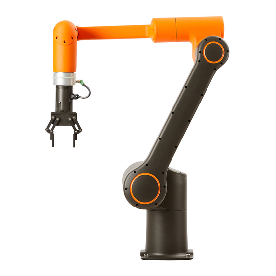
Page 17: Overview Of Robot Arms
Chapter 1 Product Overview Overview of Robot Arms Parts and joints ➊ ➎ Tool Flange Upper Arm ➋ ➏ J5_J6 ➌ ➐ Lower Arm ➍ J3_J4... - Page 18 Chapter 1 Product Overview Functions Description Name It is the area in the robot where a tool is mounted. Tool flange For more details, refer to 3.4 Connecting Tools to Robots. It is the I/O port used to control a tool. ...
-
Page 19: Overview Of Robot Controller
Chapter 1 Product Overview Overview of Robot Controller Front Name Handle Air exhaust hole (exhaust hole filter) Air intake hole (intake hole filter) Controller cover locking screw Teaching pendant fixing hook Controller fixing bracket ... -
Page 20: Bottom
Chapter 1 Product Overview Bottom Name Robot communication connector Robot power connector Power button AC power socket... -
Page 21: Overview Of Teaching Pendant
Chapter 1 Product Overview Overview of Teaching Pendant Front Description Name Turn on/off the power of the teaching pendant. Power button For more details, refer to 4.2 Turning on the Teaching Pendant. Press it to stop the robot. Emergency stop ... -
Page 22: Rear
Chapter 1 Product Overview Rear Name Description Users can insert their hands and lift the teaching Handle pendant for use. Users can turn the handle and insert their hand in the desired direction. -
Page 23: Axial Coordinates And Operational Range
Chapter 1 Product Overview Axial Coordinates and Operational Range It consists of a total of six axes and an axis of each joint has the following coordinates and operational ranges. The direction of arrow indicates the (+) rotational angle and the opposite direction of arrow indicates the (-) rotational angle. - Page 24 Chapter 1 Product Overview The J3 axis has a limited operational range due to its unique structure. Note When the J3 axis is at -85° When the J3 axis is at 245°...
-
Page 25: Robot's Working Range
Chapter 1 Product Overview Robot's Working Range The radius of rotation for the robot when its arm is fully stretched is 1300 mm. -
Page 26: Maximum Load Capacity For The Tool
Chapter 1 Product Overview Maximum load capacity for the tool The load capacity of the robot arm may vary depending on the distance between the tool flange and the payload's center of gravity. The load capacity per distance is as follows:... -
Page 27: Chapter 2 Safety
Chapter 2 Safety Chapter 2 Safety Safety Marks in the User Manual The user manual contains the following safety marks. Danger If a user does not obey the safety mark, then it can cause a severe accident including death or serious injury of a user. Warning If a user does not obey the safety mark, then it can cause an accident including serious injury of a user. -
Page 28: General Safety Cautions
Do not modify the robot on your own. If a user causes a problem by modifying or remodeling the product on their own, then Hanwha Precision Machinery will not be responsible for it in any sort of way. ... -
Page 29: Intended Use
It is recommended that you test all the functions separately before using the machine or other robot that can damage the robot. If other machine or robot is damaged by programming errors or robot failures, Hanwha Precision Machinery will not be responsible for it. -
Page 30: Potential Dangers
Chapter 2 Safety Potential Dangers If the risk assessment, conducted by the final system manufacturer who applied the robot, concludes that it is not possible to fully reduce the risk only with the built-in safety function, additional protective measures should be established. Consider potential dangers as follows: ... -
Page 31: Transportation
Chapter 2 Safety Addition of safety devices according to the risk assessment results To check whether the system is correctly designed, set up and installed Definition on how to use the system Providing information on operation and safety as well as contact information ... -
Page 32: Emergency Stop
Chapter 2 Safety Emergency Stop You can press the emergency stop button to immediately stop the robot in case of emergency. The emergency stop button is basically located in the teaching pendant and you can stop the robot by connecting another emergency stop button to the robot controller. -
Page 33: Safety Fence
The manufacturer is not responsible for the failure caused by excessive force. 2.11 Safety Controller The safety controller for HCR-12 complies with the ISO13849 Cat3. PLd class. 2.12 Risk Assessment The risk assessment is one of the important factors when configuring a robot configured... - Page 34 Chapter 2 Safety integrating it into the entire system, so it is not possible to perform the risk assessment with the robot alone. The person who configures the robot included system to perform the risk assessment of the robot should install and operate it according to instructions of ISO 12100 and ISO10218-2 standards.
-
Page 35: Chapter 3 Installation
Chapter 3 Installation Chapter 3 Installation The installer should install and operate the robot according to instructions of ISO 12100 and ISO10218-2 standards and comply with relevant requirements of international standards such as ISO/TS 15066 and local laws and regulations. The manufacturer is not responsible for accidents caused by noncompliance with relevant requirements of international standards and local laws and regulations or due to not performing review on the risk assessment as mentioned in Section 2.12. -
Page 36: Installation Types
Chapter 3 Installation Installation Types You can install the robot arm on ceiling, wall or floor as follows. Example of installation on floor You can also install it on a moving dolly. Example of installation on a moving dolly Warning If you install the robot on a moving dolly, you must make sure the moving dolly is fixed to the ground when operating the robot. - Page 37 Chapter 3 Installation After installing the robot, you must configure the robot installation information depending on each type of installation. For more details, refer to 7.1 Setting the Robot Installation Angles...
-
Page 38: Fixing Robots
Chapter 3 Installation Fixing Robots You can install the robot arm on the ceiling, wall or floor by using 4 pieces of M12 bolts not shorter than 25mm and it is recommended to fasten those bolts with 140 Nm torque. If the strength or levelness of the installation ground is not sufficient for supporting the robot arm, then you can use a fixing base for installation. -
Page 39: Connecting Tools To Robots
Chapter 3 Installation Connecting Tools to Robots Using four sets of M6 bolts, fix a tool to the tool flange. Tools and fixing M6 bolts are not included in the product package. Note The tool combination method varies from tool to tool. For more detailed methods, refer to the user manual provided by the tool maker. -
Page 40: Connecting Cables
Chapter 3 Installation Connecting Cables Connecting the robot arm to the robot controller After connecting the robot arm cable to the robot controller, hook a fixing latch, so that the cable does not slip out. -
Page 41: Connecting The Power Supply To The Robot Controller
Chapter 3 Installation Connecting the power supply to the robot controller Connect the power cable approved in your country to the power terminal. Robot controller's power terminal accepts standard IEC plugs. The minimum requirements for power supply are ground, main fuses and circuit breakers, and they should be prepared by the person who prepares for installation. -
Page 42: Fixing The Controller Box
Chapter 3 Installation Fixing the Controller Box The controller box can be fixed to the ground by using the fixing bracket at the bottom. Fix it with M14 bolts not shorter than 45 mm in combination with flat washers. Bolts or screws fixing the controller box are not included in the product Note package. -
Page 43: Overview Of Controller I/O
Chapter 3 Installation Overview of Controller I/O If you want to connect other external equipment to your controller, then you must first connect it to the I/O inside the controller box. The controller I/O is very flexible, so it can be connected to various equipment such as relays, PLC, and emergency stop buttons. - Page 44 Chapter 3 Installation By implementing the terminal block called IO Power (J8), you can supply power to the digital I/O from an internal 24V power supply or external power supply. The left two blocks are composed of internal 24V(INT_24V), GND and the right two blocks are composed of external 24V(EXT_24V), GND.
- Page 45 Chapter 3 Installation Push Button Input Push Button Input The following electrical specifications apply to the internal or external power supply. Terminal Parameter Minimum Format Maximum Unit Internal 24V power supply Voltage INT – ING Current External 24V requirements Voltage EXV –...
-
Page 46: Configuring The Safety Input
Chapter 3 Installation Terminal Parameter Minimum Format Maximum Unit Digital input EIx/SIx/FIx/DIx Voltage EIx/SIx/FIx/DIx OFF area EIx/SIx/FIx/DIx ON area EIx/SIx/FIx/DIx Current (11-30V) EIx/SIx/FIx/DIx Functions Format EIx/SIx/FIx/DIx IEC 61131-2 Format Configuring the Safety Input Since a single signal loss should not lead to a loss of the safety function, all the I/O's related to the safety should be duplexed. -
Page 47: Initial Safety Configuration
Chapter 3 Installation Using the Flexible I/O, you can set the Safety I/O additionally. For example, you can use the emergency stop output. In addition, you can configure the Flexible I/O for the safety function in the GUI. Danger Do not connect safety signals to normal PLCs. -
Page 48: Connecting The Emergency Stop Button
Chapter 3 Installation Connecting the emergency stop button It is recommended that you connect one or more emergency stop button. The emergency stop button is composed as follows. Safety protection stop and restart As an example of basic safety protection device, basically, when the door opens, you can press the door switch to stop the robot. -
Page 49: Configuring The General Digital I/O
Chapter 3 Installation 3.10 Configuring the General Digital I/O If not used as a safety function, then you can use the Flexible I/O as a general purpose digital I/O. The general digital I/O should comply with the common specifications of digital I/O. The general digital I/O can be used to configure relays or PLC systems. -
Page 50: Digital Input Control Using Buttons
Chapter 3 Installation Digital input control using buttons You can connect a simple button to a digital input. You can configure it as follows. Communicating with other equipment or PLC The digital I/O can be configured to communicate with other equipment if a common GND is established and if the equipment uses PNP technology. -
Page 51: Configuring The General Analog I/O
Chapter 3 Installation 3.11 Configuring the General Analog I/O It can be used to set or measure voltage (0-10V) or current (4-20mA) between two equipment. For high reliability, it is recommended that you use the following method. Use the analog ground closes to the I/O. ... -
Page 52: Analog Output
Chapter 3 Installation Analog output You can use analog outputs as speed control inputs to the conveyor belt. You can configure it as follows. Analog input You can use analog sensor outputs as analog inputs. You can configure it as follows. -
Page 53: Chapter 4 Getting Started
Chapter 4 Getting Started Chapter 4 Getting Started Turning on the Robot Controller Turn on the power switch at the bottom of the controller. If you turn on the power switch for the controller, power will be supplied to the controller. -
Page 54: Turning On The Teaching Pendant
Chapter 4 Getting Started Turning on the Teaching Pendant Turn on the power button at the left top of the teaching pendant. Caution Do not turn on the teaching pendant with USB devices connected. It may cause problems with starting the system. Connect it after the system is booted completely. -
Page 55: Chapter 5 Software Overview
Chapter 5 Software Overview Chapter 5 Software Overview Menu Overview Expanding menu Press the expanding menu button at the left top of the screen to expand the menu. You can check the name of each menu and if a sub menu exists, then you can select it as well. -
Page 56: Monitoring
Chapter 5 Software Overview Monitoring You can check the real time condition of the robot arm. For more details, refer to Chapter 11 Monitoring Robot Setting You can configure the installation information before operating the robot. For more details, refer to Chapter 7 Setting Robots. -
Page 57: 3D Preview Screen
Chapter 5 Software Overview 3D Preview Screen The system provides a screen where you can preview the robot's movement or coordinates in 3D. You can drag on the screen in the desired direction to change the screen perspectives. Screen display setting button You can configure the information displayed on the preview screen and the screen layout. -
Page 58: Robot Task Control Button
Chapter 5 Software Overview Additional setting button Hide or unhide the point of the movement path for the tool currently programmed. Hide or unhide the location/direction of the TCP currently set for the robot. Hide or unhide the movement path currently programmed. Hide or unhide the safety borders currently set for the robot. -
Page 59: Manual Move Screen
Chapter 5 Software Overview Manual Move Screen On this screen, you can control the robot's positions. By using jog control or direct teaching, you can control the robot's position. Manual Move button in the main menu. Press the Coordinate System: Selects Coordinate System for manual move. (View, Base, TCP) ... - Page 60 Chapter 5 Software Overview - Rotating Range : 0.01~ 10degree Depending on the purpose of the menu that uses the manual robot control Note function, the screen layout may differ accordingly. If you press the coordinate value on the screen, the screen will be changed as follows, and then you can enter the coordinates and the joint angles on your own.
-
Page 61: Virtual Keypad
Chapter 5 Software Overview When using the direct teaching function, check that the center of gravity of the TCP payload is correctly entered. Entering an incorrect value may cause malfunction. If you drive a joint beyond a certain speed while using the direct teaching function, it may make a noise and make an emergency stop for the safety of operators. -
Page 62: Number Keypad
Chapter 5 Software Overview Number keypad You can enter or edit simple numbers. If you want to display your inputted numbers, press the Enter key. If you want to delete the entire inputted text string, press the button. ... - Page 63 Chapter 5 Software Overview Add an expression: Select a green input field and press the Add button. The selected green input items will be changed to the three basic input items and added into the parenthesis. Delete an expression: After selecting any item in the parenthesis, press the Delete button. ...
-
Page 64: Chapter 6 Registering Robots And Users
Chapter 6 Registering Robots and Users Chapter 6 Registering Robots and Users After installing the robot, turn on the system for the first time. Only the Management menu will be seen. If there is no robot registered, other menus will not be seen. Managing Robots You can register a new robot to be linked to the controller or change the robot name. -
Page 65: Registering Robots
Chapter 6 Registering Robots and Users Registering robots Press the Add button. Add a robot and press the OK button. Enter the robot name and press the Apply button. When the restart confirmation window appears, press the OK button. You must restart the system for normal operation. -
Page 66: Modifying The Robot Name
Chapter 6 Registering Robots and Users Modifying the robot name In the list of registered robots, select a robot. After pressing the text box having the robot name, modify it as you want. Press the Apply button. -
Page 67: Managing Users
Chapter 6 Registering Robots and Users Managing Users You can make sure only specific users can use the software by registering them. Also, you can grant an individual right to each user to limit their access to the menus. Management > User. In the main menu, select Adding users and setting authorities Press the Add button. -
Page 68: Menu Available To Each Authority
Chapter 6 Registering Robots and Users You can choose one of the following two authorities. − Admin: Can use all the functions of the software. − Operation: Cannot use the safety and the critical setting functions. Settings can be all inquired about. -
Page 69: Login/Logout
Chapter 6 Registering Robots and Users Main menu Sub menu Admin Operator Log Off User Robot Management Setting Management General Network Configuration SW update Shutdown Zeroing Robot The Zeroing Robot menu is only accessible by the Super Admin Note user. -
Page 70: Logging Out
Chapter 6 Registering Robots and Users Logging out While logged in, the icon is displayed at the right top of the screen. While logged in, icon and press the Logout button. press the Checking Status Checking the robot status By pressing the robot icon in the Robot Selection button or the status icon at the right top of the screen, you can check the robot's status. -
Page 71: Checking The Software Version
Chapter 6 Registering Robots and Users Checking the software version You can check the current version of the operating software and control software by clicking the information display icon at the top of the screen. Operating software: Displays the operating software version. ... -
Page 72: Chapter 7 Setting Robots
Chapter 7 Setting Robots Chapter 7 Setting Robots Setting the Robot Installation Angles After installing a robot, you must set the robot installation angle. The purpose of this process is to make sure that actual operation of the robot arm looks same as what we saw in the preview screen and let the controller know the direction of gravity. -
Page 73: Setting Tcp
Chapter 7 Setting Robots Depending on the tilt of the ground where the robot arm's base is installed, set the angle accordingly. If installed on the ground, press 0°, if installed on the ceiling, press 180° You can touch the gauge or press the left/right buttons to fine tune the tilt for the X/Y axis. -
Page 74: Creating A New Tcp Profile
Chapter 7 Setting Robots Warning If the TCP profile is incorrectly entered, accidents such as collision and jamming may occur while operating the robot and the robot may operate incorrectly while using the direct teaching function. In addition, as the singularity of the robot arm may vary depending on the TCP, the program previously prepared may not work or the robot arm may not operate as expected. - Page 75 Chapter 7 Setting Robots Tool Length: Indicates the tool length. The tool length is automatically calculated but users cannot enter it on their own. Payload: Set the tool weight. If not specified, it will not be saved and an error message will appear. Press the Save button.
-
Page 76: Calculating The Tcp Position
Chapter 7 Setting Robots Calculating the TCP position By using the direct teaching function, you can calculate the position of TCP. To calculate the position of TCP accurately, receive the position data from various angles with respect to one point and analyze them. After moving a tool to face a certain point at P1, enter the position data. - Page 77 Chapter 7 Setting Robots To calculate the position of TCP, proceed as follows. After pressing the Edit button, press the Position button. Press the Teaching button.
- Page 78 Chapter 7 Setting Robots Press the P1 button when it is activated. If you press the P1 button, the Manual Move screen will appear. While pressing down the Direct Teaching button in the Manual Move screen, move the robot arm to place the tip of the tool right at the reference point. For more descriptions on the Manual Move screen, refer to 5.3 Manual Move ...
-
Page 79: Setting The Tcp Orientation
Chapter 7 Setting Robots Press the Calculate button. The Calculate button will be activated only if the minimum three points are set properly. Check the calculated position result and press the Apply button. Press the Cancel button to cancel the task. ... - Page 80 Chapter 7 Setting Robots Press the Set Orientation button. If you press the Set Orientation button, the Manual Move screen will appear. In the Manual Move screen, use jog control and Direct Teaching button to adjust the tool orientation as follows. For more details on the Manual Move screen, refer to 5.3 Manual Move Screen.
-
Page 81: Changing The Tcp Profile Name
Chapter 7 Setting Robots Press the Apply button to apply the settings to the system. Press the Cancel button to cancel the task. Changing the TCP profile name Select the TCP setting profile to modify. Press the Edit button. Press the Rename button. -
Page 82: Deleting The Tcp Profile
Chapter 7 Setting Robots Deleting the TCP profile After checking the name of TCP profile currently used by the selected robot, and proceed as follows. Select the TCP profile to modify. Press the Delete button. You cannot delete the TCP profile currently being used by another robot. ... -
Page 83: Setting Inputs/Outputs
Chapter 7 Setting Robots Setting Inputs/Outputs By changing the name of I/O used by the controller, you can make sure they are easily detected and also assign a function to be executed depending on the input/output signals. Robot Setting > I/O Setup. In the main menu, select Types of digital I/O There are three types of digital I/O as follows. -
Page 84: Editing The Digital Inputs/Outputs Settings
Chapter 7 Setting Robots Editing the digital inputs/outputs settings Press the Edit icon for the digital I/O item to modify. The following edit window will appear. Name: Use a name easy for a user to identify or the existing name. ... -
Page 85: Types Of Analog I/O
Chapter 7 Setting Robots Name: Use a name easy for a user to identify or the existing name. You cannot use the same name already in use by another I/O. Max 15 letters (30 bytes) are allowed. Special characters cannot be used. Command: When the robot is in the state of the set command, the value set(Low/High) ... -
Page 86: Editing The Analog I/O Setting
Chapter 7 Setting Robots Editing the analog I/O setting Press the Edit icon of the analog input or output item to modify and the editing window will appear as follows: Name: Use a name easy for a user to identify or change the existing name. ... -
Page 87: Coordinates
Chapter 7 Setting Robots Coordinates You can set the location information that is available in the program and other setup menus. From the main menu, select Robot Settings > coordinates. Point: Add a point. Line: Add a line consisting of two points. ... -
Page 88: Registering Line Coordinates
Chapter 7 Setting Robots Registering line coordinates You can add and set line coordinates. Click point 1 and point 2 to set two points to define a line. Coordinate system information - Reference point: The first point becomes the reference point. - Y axis: The direction of the first point to the second point is the Y axis. -
Page 89: Setting Global Variables
Chapter 7 Setting Robots Setting Global Variables You can set the global variables that are available and shared by many programs by restarting the system. Variable name: Specifies a variable name. − Up to 10 characters (20 bytes) can be entered. ... -
Page 90: I/O Bit Operation
Chapter 7 Setting Robots I/O Bit Operation You can combine the values of multiple digital I/O inputs, and assign them to variables or assign them to actions. Add/Delete Add or delete bit operation settings. Clicking the Add button adds one setting, and the initial value of each IO is displayed as Low. -
Page 91: Chapter 8 Safety Settings
Chapter 8 Safety Settings Chapter 8 Safety Settings After configuring the installation settings, you must configure the safety settings to protect users against the dangerous situation that can arise during robot operation. Warning Make sure to check safety settings immediately after the robot is installed. In addition, all of the functions for safety settings must be regularly checked. -
Page 92: Default Settings
Chapter 8 Safety Settings Default settings Depending on the limitation on each item, four sets of default settings are provided. If you want to use the default setting, check Preset and select one out of the four choices. Manual setting method If you want to set each item on your own, you can use the adjustment bar to change the value while Preset is not checked. - Page 93 Chapter 8 Safety Settings There are four different ways to limit the robot's movement. Torque: You can limit the max force that the robot(TCP) is exerting to the outside. Force: TBD Speed: You can limit the max speed for the TCP's linear movement. ...
-
Page 94: Setting Safety Boundaries
Chapter 8 Safety Settings Setting Safety Boundaries To improve user safety, you can build virtual fences around the robot to prevent the TCP from moving beyond the boundary of these virtual fences. Safety Setting > Safety Boundary in the main menu. Press Adding safety boundary planes After adding multiple safety boundary planes, if necessary, you can select one of them... -
Page 95: Viewing Safety Boundary Planes
Chapter 8 Safety Settings In the Manual Move screen, use jog control and Direct Teaching button to set the boundary position. For more details on the Manual Move screen, refer to 5.3 Manual Move Screen. Your safety boundary will be created in a location that is separated from the center axis of the flange as much as the TCP length set in the TCP. -
Page 96: Applying Safety Boundaries
Chapter 8 Safety Settings : To display in the preview screen. : Not to display in the preview screen. Press the Info icon to check the coordinates for the safety boundary. Point: Indicates the center of the 3-D where the center of the safety boundary is located. ... -
Page 97: Changing The Name Of Safety Boundaries
Chapter 8 Safety Settings Press the Apply button. Press the Cancel button to cancel the modifications and revert to the previous settings. If there are eight or more safety boundary planes in the list, press the up/ Note down button to scroll. - Page 98 Chapter 8 Safety Settings Press the OK button.
-
Page 99: Setting Tool Boundaries
Chapter 8 Safety Settings Setting Tool Boundaries The user sets the safety boundary of the set tool, so that the tool does not go beyond the safety boundary of the set working area. Adding Tool Safety Boundary Surfaces The safety boundary of the tool can be set only for TCP settings that have already been set. -
Page 100: Setting Tool Safety Boundary Surfaces
Chapter 8 Safety Settings The tool boundary surfaces can be set in the following 4 types: Box: Box-shaped boundary surface with TCP as the center having the Z axis of the TCP as the height and the X axis as the width ... -
Page 101: Applying Tool Safety Boundary Surfaces
Chapter 8 Safety Settings Applying Tool Safety Boundary Surfaces Switch the boundary surface you want to set to the TCP to Use or Not Use. Press the Apply button. Press the Cancel button to cancel the current settings and return to the previous setting. - Page 102 Chapter 8 Safety Settings In case of digital outputs, the high or low signal is sent for the assigned function. Press the Add button. Select an I/O terminal to be used as redundant I/O. Set the function to be assigned. ...
-
Page 103: Setting Safeguard I/O
Chapter 8 Safety Settings Setting Safeguard I/O The user sets the safeguard stop. Safety Setting > Safe Guard. In the main menu, press Assign a Safeguard Stop function with the IO. Click Apply button to apply to the system. ... -
Page 104: Exceeding Safety Limit Of Joints
Chapter 8 Safety Settings Exceeding Safety Limit of Joints If the safety limit of any joint is exceeded, information on the joint exceeding the safety limit is displayed at the top of the screen, as shown in the figure below. If the safety limit of a joint is exceeded, the system will not operate normally. -
Page 105: Chapter 9 Programming
Chapter 9 Programming Chapter 9 Programming You need to program the movement ahead of time if you want your robot to perform a certain task. Programming in the main menu. To program your robot, select How to Use Commands Selecting a flowchart There are two types of flow charts - main and sub. -
Page 106: Type Of Commands
Chapter 9 Programming Type of commands You can use the following commands in your programming - Move, If, Loop, Switch, Halt, Wait, Set, Loop, Pattern, Sub Program, and Vision. Set the point that the TCP will move to. Move For more details, refer to 9.7 Move command. -
Page 107: Additional Commands
Chapter 9 Programming Additional Commands In addition to the basic commands, the additional commands that appear when the View Command button is clicked are Folder, Halt, Vision, Pattern, Script, and Path. Groups the created program command icons and bundles the Folder programs into a sub-folder. -
Page 108: Entering Commands
Chapter 9 Programming Entering commands Each time you press a command, it is inputted in the timeline one by one. After programming is complete, select the icon to repeat the entire program continuously. If it overflows to the next screen due to too many commands in the flow line, you can press the up/down or left/right buttons to scroll. -
Page 109: Deleting Commands
Chapter 9 Programming After entering a command in the timeline, press the command name to modify the name. Deleting commands Select a command to delete in the timeline. Press the Delete button. Searching Commands Click the Search button to display the search function on the screen. Enter the name of a command to be searched, and perform a search. -
Page 110: Tree
Chapter 9 Programming Check the Skip setting. Commands that have been set to Skip are grayed out, and will not be executed during program execution. Tree If you click the , all the commands programed are displayed in Tree structure. The commands in the Tree and the command icons in the flowchart are displayed in synchronization with selection or program progress. -
Page 111: Setting Variables
Chapter 9 Programming Setting Variables You can manage variables such as adding/deleting/modifying variables to be used in the program. Press the variable management menu button at the end of the command list. When you press the variable management button, a screen for variable management and monitoring is displayed at the top, as shown below. -
Page 112: Modifying Variables
Chapter 9 Programming Modifying variables Press the field if you need to change the variable name or value. Change it to the desired name or value and press the OK button. The max length of variable is limited to 10 letters. ... -
Page 113: Editing Programs
Chapter 9 Programming Editing programs If you want to change the order or structure of commands entered in the timeline, then press the Edit menu button at the end of the command list. You can also press the command in the timeline for more than three Note seconds to open the Edit menu. -
Page 114: Example Of Program Editing
Chapter 9 Programming Example of program editing In this example, you can cut a command entered in the timeline and paste it onto another location. Select a program command to be pasted onto another location. The red number marked when a command is selected indicates the order of pasting. In the edit menu, press the Cut button. -
Page 115: Undo Function
Chapter 9 Programming Undo Function You can use the edit function to undo edits made Undo to items. Redo You can redo an edit that has been undone. . Up to 50 steps are saved. Note . The edit history is initialized when you open a New File, File Open or Cancel. -
Page 116: Anaging Arogram
Chapter 9 Programming Managing a Program At the bottom of the programming window, press the File button to save, load or delete the program. Saving a program To save the completed program, select File > Save at the bottom of the screen. Enter the program name and press the OK button. -
Page 117: Loading A Program
Chapter 9 Programming Loading a program To load the saved program, select File > Load at the bottom of the screen. Select a program to load and press the OK button. Deleting a program To delete the saved program, select File > Load at the bottom of the screen. Select a program to delete and press the Delete button. -
Page 118: Export As Script
Chapter 9 Programming Export as script To save the program as a script, select File > Export as script at the bottom of the screen. Enter the file name and press the OK button. Export Program File You can save the program and the configuration file of current system To save the program, select File >... -
Page 119: Using Templates
Chapter 9 Programming Using Templates You can save the prepared program structure as a template. Only the entire program structure is saved but the option for each command is not saved. Saving as a template To save the completed program as a template, select Template > Save at the bottom of the screen. -
Page 120: Loading A Template
Chapter 9 Programming Loading a template To load the saved template, select Template > Load at the bottom of the screen. Select a template to load and press the OK button. Deleting a template To delete the saved template, select Template > Load at the bottom of the screen. Select a template to delete and press the Delete button. -
Page 121: Applying Programs
Chapter 9 Programming Applying programs Before applying the program results to the robot or actually using it, it is necessary to do a simulation. If you want to link the program to an actual robot or check it in previews, press the Apply button. -
Page 122: Move Command
Chapter 9 Programming Move command The command is used to move the robot arm by designating the destination and the movement method. Selecting a movement method There are three ways to move as follows and you can set the tool speed and acceleration for each method. - Page 123 Chapter 9 Programming Arc: A tool moves along the circumscribed circle whose center is the circumcenter of a triangle formed by the starting point(S) and the two points (W − Speed: 0.1 mm/s ~ 1000 mm/s − Accel. (Acceleration): 1 mm/s ~ 2500 mm/s The TCP coordinates of the last position held by the robot are the Note...
-
Page 124: Radius Of Linear
Chapter 9 Programming Radius of Linear If you use the radius in Linear movement and the next command is Linear movement, it moves the curve without stopping when moving between commands. The minimum radius is zero. If you set the radius to zero, then its path is not a curve. ... - Page 125 Chapter 9 Programming Select Blending (You can’t use it at the same time with Don’t stop at this point function) Enter the radius. The maximum radius is calculated based on the coordinates of the next move command as below. Moving path when radius within driving range : Start point of blending : Waypoint of blending and...
-
Page 126: Advanced
Chapter 9 Programming Advanced The command is used to control digital output while moving. Select Advanced Add the digital outputs to control and set the values of them. Setting the coordinates for movement To set the movement coordinates, you can either use an absolute value that is fixed in the space or a relative value that is relative to the previous location. -
Page 127: Displaying As Groups
Chapter 9 Programming Fixed Point: The 3D coordinate is received from the robot's coordinate system and used as the movement coordinate. Press the Set button to launch the Manual Move screen. For more details about − the Manual Move screen, refer to 5.3 Manual Move Screen. -
Page 128: If Command
Chapter 9 Programming IF Command Use the command to initiate different commands depending on the condition. Enter the condition in an IF statement. Press the text box to launch the formula keypad. For more details about the formula keypad, refer to 5.4 Virtual Keypad. -
Page 129: Loop Command
Chapter 9 Programming − When Else If is executed : If Else If is present in the child, execute the Else If program command that meets the current condition. If Else is present in the child, execute the Else program command. LOOP Command Use the command to repeatedly execute a series of commands. -
Page 130: Switch Command
Chapter 9 Programming it becomes False, the executing command is stopped, the Loop command is stopped, and the next program command is executed. 9.10 SWITCH Command Use the command to execute a different command depending on each specific case. An IF command is executed after assessing all the conditions branching to Else IF, but a SWITCH command is executed immediately by finding the corresponding case, thus it is much faster than execution of an IF command. -
Page 131: Wait Command
Chapter 9 Programming 9.11 WAIT Command Instruct the robot to wait for a certain period. Disabled: Do not use a Wait command. Waiting time: Enter the duration of waiting time. Digital: Wait until a digital signal is inputted to a specific digital input terminal. ... -
Page 132: Set Command
Chapter 9 Programming 9.12 SET Command You can set a digital or analog output value or assign a specific value to a variable or even change the TCP profile currently in use. Disabled: Do not use a SET command. Digital: Set a specific digital output value. -
Page 133: Folder
Chapter 9 Programming 9.13 Folder Program command icons can be grouped into folders. Change Programed Icons into Folder Click the Edit icon. Select icons that you want to group into folder. Click the Combine Folder icon. When converting a folder, the folder is created at the last location of the program. Create New Folder In the Commands view, click the Folder icon to create a folder. -
Page 134: Message
Chapter 9 Programming 9.14 Message Displays a user-defined statement or variable in a pop-up or console window. The command can be added from the Command Extension tab. Output format Pop-up: Displays a pop-up window with messages. List: Displays messages in the lower left console window. Message operation If you set the message format as pop-up, you can specify the operation accordingly. -
Page 135: Message Format
Chapter 9 Programming Message format User message: Outputs the message the user has entered. Variable output: Selects the variable to which to output the value. Select message Write a message in advance and save the text file to the USB in UTF-8 format. ... -
Page 136: Pattern Command
Chapter 9 Programming 9.15 PATTERN Command If the robot repeatedly executes the same task along the same path, you can define it as a pattern by using this command. Pattern types There exist the following five types of patterns. Stack pattern: In this pattern, the robot stacks objects while vertically moving with certain intervals. -
Page 137: Setting The Pattern Coordinates
Chapter 9 Programming Box pattern: In this pattern, the robot also repeats the same task vertically which it performs in a square pattern. Setting the pattern coordinates After selecting a pattern to use, set the coordinates that determine the type of pattern. The following image illustrates a box pattern. -
Page 138: Setting Repeat Counts
Chapter 9 Programming Setting repeat counts For every pattern, you need to set repeat counts between the starting point and the end point on each side. Count (n): the number of repeated movements on a side Interval (d): the distance that the robot moved each time ... -
Page 139: Setting Pattern Points
Chapter 9 Programming If starting position and variable movement are used together, starting position is given priority. Setting pattern points If you enter a pattern command in the timeline, then the line to set the pattern point and icon will be added. When each pattern repeats, if you immediately move to the next destination, then you can get interfered by an obstacle. -
Page 140: Using A Sub Program
Chapter 9 Programming 9.16 Using a Sub Program In the main program, you can call multiple sub programs for use. Making a sub program In the flow chart, press the Sub tab. Press the subprogram button in the command menu of the Sub tab. Once the subprogram button is pressed, a new sub program will be created. -
Page 141: Saving And Loading A Sub Program
Chapter 9 Programming After pressing the sub program, create a program that will be used as a sub program. Once the sub program is pressed, available commands will appear in the command menu and a time line will be created, so that you can prepare a program. Saving and loading a sub program After creating a sub program in the Sub tab, you can save it as a file or load the sub program or template. - Page 142 Chapter 9 Programming Press the Sub-program button. After selecting a sub program, the sub program name will be displayed on the button. Select a sub program for use and press the Select button. Once a sub program is selected, the subprogram command will be added to the timeline as shown below, and a sub program line will be added at the bottom to indicate the content of the sub program.
-
Page 143: Conveyor
Chapter 9 Programming In the main program, you can modify the content of sub program but you Note cannot save it. If you want to save modifications made for the sub program in the main program, you must save it in the Sub tab. 9.17 Conveyor Executes operations linked with conveyor movement. -
Page 144: Conveyor Start Options
Chapter 9 Programming Conveyor Start Options If the I/O set in the trigger satisfies the condition, it starts tracking the conveyor. Trigger : Set the I/O and condition that trigger the start of conveyor tracking. Only Digital Input is available. Setting Conveyor Command Set the actions to be executed during conveyor tracking. -
Page 145: Vision Command
Chapter 9 Programming 9.18 VISION Command You can communicate with a vision equipment by using the vision data configured in the Device Setting menu. Setting basic options Press the drop-down menu to select a desired vision equipment and set the waiting time and the data receiving option. -
Page 146: Setting The Movement Location
Chapter 9 Programming The same input range of speed/acceleration is used as in linear movement. Variable setting: If there is a variable registered by the user, it can be used to store whether to recognize the vision. If you select a variable, it stores the success or failure during program execution, and you can program it using the corresponding variable in the next program. -
Page 147: Thread
Chapter 9 Programming 9.19 Thread When a robot program is executed, it is possible to execute parallel programs that require IO and other controls in parallel with the Main program. However, Move-related commands cannot be used. Thread Tab Select the Thread tab to create a thread. Click the drop-down menu to select the vision device you want to use, and set the wait time and data reception options. -
Page 148: Thread Creation
Chapter 9 Programming Thread Creation Multiple threads can be created. Like a sub-program, each Thread is clicked on as an icon and added to the timeline in the lower layer. Commands to control the motion of the robot cannot be used. Note Event Tab Create Thread which has condition. -
Page 149: Script
Chapter 9 Programming 9.20 Script Provides the function to edit the robot script and set it as a robot command. Script Viewer Displays a created script. While the program is running, a line currently proceeding in real time is displayed on the screen. EDIT: You can edit the edit window by opening it. -
Page 150: Path Command
Chapter 9 Programming 9.21 Path Command You can create a motion by holding the robot arm directly. Recording Paths Starting to record Click the button and move the robot arm along the path you want to record. During recording, the recording status is displayed in a pop-up window, and can be canceled or stopped. - Page 151 Chapter 9 Programming Apply Once you have confirmed the motion, click the Apply button to save it as a file. Speed: Sets the execution speed of the recorded motion. Import: Imports an already recorded motion. Export: Saves the recorded motion separately. ...
-
Page 152: Chapter 10 Starting The Robot
Chapter 10 Starting the Robot Chapter 10 Starting the Robot Starting the robot means that you are powering up the servo motor and get ready for its operation. Robot Operation in the main menu. Select If your robot is already registered, then it will appear in the initial screen Note after booting up the system. -
Page 153: Turning On/Off The Robot
Chapter 10 Starting the Robot Turning ON/OFF the robot You can check the start/end status of your robot at present, and turn on or off the robot. ON: Power up the motor for the robot joints and get ready for robot operation. If the ... -
Page 154: Checking And Setting The Robot Operation Data
Chapter 10 Starting the Robot Checking and setting the robot operation data You can check the effective weight applied to the currently selected robot and quickly retrieve the saved robot settings and program and apply them to the system. Reset: If the robot is malfunctioning or uncontrollable temporarily then initialize the ... -
Page 155: Operating The Robot
Chapter 10 Starting the Robot Operating the robot If you want to operate your robot according to the program selected in the operation setting, then press the button in the preview window. For more details about the preview screen, refer to 5.2 3D Preview Screen. -
Page 156: Locking Screen
Chapter 10 Starting the Robot Manual: Manually move robot through the manual contro. Play: Start program from current position. If the robot is not at the start position of the program, it moves to the start position and the program starts. Cancel : Cancel Playing program. -
Page 157: Chapter 11 Monitoring
Chapter 11 Monitoring Chapter 11 Monitoring You can check the selected robot's position/status and I/O status in real time. 11.1 Monitoring the Robot You can check the robot's position and status in real time. Monitoring > Robot Status in the main menu. Select Monitoring the robot positions In the robot position tab, you can check the position of the selected robot (joint angle... -
Page 158: Checking The Robot Status
Chapter 11 Monitoring Checking the robot status In the robot status tab, you can check the selected robot's power consumption, voltage or current. The monitoring values are displayed when the robot is running normally. Note 11.2 Monitoring Inputs/Outputs You can check and set the real time I/O status of robot. Monitoring >... -
Page 159: Monitoring Controller Inputs/Outputs
Chapter 11 Monitoring Monitoring controller inputs/outputs In the I/O Status tab, the status of signals transmitted to and received from the I/O terminal of the controller are displayed in real time. You can press the I/O status icons to switch digital outputs to high and low. For example, if you press (High) then it switches to (Low). -
Page 160: Monitoring Tool Inputs/Outputs
Chapter 11 Monitoring Monitoring tool inputs/outputs In the Tool I/O Status tab, the status of signals transmitted to and received from the I/O terminal of the tool flange are displayed in real time. A tool's digital inputs/outputs and analog inputs are set and displayed in the same way those of the controller are set and displayed. -
Page 161: Unilization
Chapter 11 Monitoring 11.3 Unilization You can check the robot's system operation time, servo start, and the program operation time information. Monitoring > Utilization in the main menu. Select Cumulative system operation time: Total cumulative system operation time from production time to present The basic unit for collecting the operation time is every hour;... -
Page 162: Chapter 12 Device Setting
Chapter 12 Device Setting Chapter 12 Device Setting You can link your robot to an external equipment such as a PLC, a vision equipment (object detection camera), and conveyor system. Different external equipment is supported depending on the S/W version. Note 12.1 Configuring MODBUS TCP... -
Page 163: Registering Devices
Chapter 12 Device Setting Registering Devices To use MODBUS I/O, register a device to share I/O information with. Press the Add button. Enter following information in the Add Device screen and press the Add button. Device Name: Enter the device name to be displayed on the screen. ... -
Page 164: Editing/Copying The Device Settings
Chapter 12 Device Setting Description: You may enter the description for the device. You can enter up to 25 characters. Editing/copying the device settings You can modify settings for a device previously registered or copy the device settings to use as settings for a new device. -
Page 165: Registering I/O
Chapter 12 Device Setting Deleting a device in the list Select a device to delete from the list. Check the check box for the device. button, and then press the OK button. Press the Delete When you delete a device, I/Os for the device will be deleted as well. Registering I/O After you registered a device, you must set an I/O or I/Os for it. -
Page 166: Viewing The Communication Status
Chapter 12 Device Setting Select a device to add an I/O to from the device list. When a device is selected, I/Os currently added to it are displayed. Press the Add button. Enter information of the I/O and press the OK button. Name: Enter the user identifiable name of the I/O. -
Page 167: Viewing And Setting The I/O Values
Chapter 12 Device Setting Normal Unable to connect Input value error Device response delay Address error Viewing and setting the I/O values After an I/O is registered, you can view or set its value. Digital Input: Indicates an icon for the digital value (High/Low) currently being input. −... -
Page 168: Editing I/O Settings
Chapter 12 Device Setting Register Output: Indicates the value being currently sent to the device. Press the value to change it. Editing I/O settings Press the Edit button of an I/O to be modified from the I/O list. Modify the settings and press the OK button. It is not allowed to change the I/O type. -
Page 169: Using A Vision System
Chapter 12 Device Setting 12.2 Using a Vision System You can register the vision to be linked to the robot and configure necessary settings. Device Setting > Vision System. In the main menu, press To interwork with the vision, the following two steps are required. Vision System Setting ... -
Page 170: Adding And Setting Vision Equipment
Chapter 12 Device Setting Robot System Setting Interworking vision setting: Sets the model and communication connection information of the vision to be interworked. Vision workspace setting: One vision camera can have a number of vision work areas, and by using the information set by the 'Vision workspace setting,' the vision coordinates recognized by the vision are converted into the robot coordinates to move the robot. - Page 171 Chapter 12 Device Setting To perform the connection test correctly, the vision system and our system Note must be connected to a single network before the test. Vision Type: Select a type of vision installation. Embedded: Attached to the robot arm. −...
-
Page 172: Setting Vision Workspace
Chapter 12 Device Setting 12.4 Setting Vision Workspace Vision workspace setting sets information to change the vision coordinate recognized by the vision to the robot coordinates. Up to 5 workspaces can be set for one vision. Adding Vision Workspace To add a vision workspace, select the vision already added from the vision list. -
Page 173: Understanding Rotation Offsets
Chapter 12 Device Setting Vision Test: Test vision with the set values. Set Points: It matches the number of guide image and is activated by clicking the number. The initial value is ‘0’. At each number, enter the robot coordinate values and the coordinates of the vision system at that point. - Page 174 Chapter 12 Device Setting B. When the scanning location and the robot's location are shifted by X°...
-
Page 175: Chapter 13 Environment Setting
Chapter 13 Environment Setting Chapter 13 Environment Setting 13.1 General Setting You can select the desired UI language and unit also set the time/date. SW Configuration > General. In the main menu, press Language Selection: You can select a language for the UI. ... -
Page 176: Network Setting
Chapter 13 Environment Setting The language and unit settings are immediately applied to the system Note without restarting it, but the time/date are applied to the system after restarting it. 13.2 Network setting You can configure the network settings for Ethernet communication of your operation software. -
Page 177: Chapter 14 Turning Off The System
Chapter 14 Turning Off the System Chapter 14 Turning Off the System 14.1 Shutting Down the Operation Software To shut down the operation software, proceed as follows. SW Configuration > Shutdown in the main menu. Select Press the OK button. ... -
Page 178: Chapter 15 Maintenance
An inspector should prepare and execute an inspection plan. The following items require periodic inspections. If you found some problems during inspections, and you can resolve them on your own, contact Hanwha Precision Machinery Co. Inspection item... -
Page 179: Checking The Robot Arm
Chapter 15 Maintenance 15.2 Checking the Robot Arm Inspection period Inspect at least once every 6 months. The inspection period may vary depending on the inspection area. Checking and cleaning the robot arm Move the robot arm to home. Turn on the controller. Check the followings. -
Page 180: Cleaning And Replacing The Filter
Chapter 15 Maintenance If there are dusts, then use a vacuum cleaner to carefully remove dusts. Check if the connector cables are connected properly. Cleaning and replacing the filter The controller has an air suction hole and an air discharge hole, which have dust filter mounted in them. -
Page 181: Viewing And Managing Logs
Chapter 15 Maintenance 15.4 Viewing and Managing Logs You can view and manage the logs for the operation system. Select Management > Log in the main menu. Deleting Logs Press the Delete button and the log data found will be deleted. Exporting Logs Press the Export button. -
Page 182: Managing The Robot System Configuration
Chapter 15 Maintenance When export is finished, a folder in the form of 'date-time' is created at the selected location, and the log data are saved in the folder along with the robot configuration and program files. 15.5 Managing the Robot System Configuration You can save the robot configuration in a local or external storage device or retrieve the saved robot configuration from them. -
Page 183: Factory Reset
Chapter 15 Maintenance Factory reset Initializes the system to its factory settings. A warning message is displayed twice before the reset is performed. When the factory reset is complete, the system restarts. If you perform a factory reset, all information including the robot Note information will be deleted. -
Page 184: Importing The Configurations
Chapter 15 Maintenance Select a robot to export the settings for. Press the refresh button to update the storage list and the file list. Press the filename input field and enter the filename. Filename is limited to 25 letters, and empty character is not allowed. Press the Export button. - Page 185 Chapter 15 Maintenance When the confirmation window appears, press YES.
-
Page 186: Software Update
The update function is not available for general users but for the user with a certain authority. If you need an update, contact Hanwha Precision Machinery or a local service center. Updating the operation software... - Page 187 Chapter 15 Maintenance Connect the external storage device (such as the USB memory) where the update files are stored to the USB port of the teaching pendant or the controller. In the software update screen, press the Import button. Select an update file in the correct location and press the OK button. ...
-
Page 188: Appendix Awarranty
Appendix A Warranty Refer to the contract between the sales team and you. Warranty Our company guarantees specifications, quality and reliability that our customer demands during the warranty period. Warranty period One year since the date of equipment purchase (varies depending on the contract between our company and you.) Limitation of Liability ... -
Page 189: Appendix Bcertification
Appendix B Certification Safety... -
Page 190: Md(Machinery Directive)
MD(Machinery Directive) -
Page 191: Emc (Electro Magnetic Compatibility)
EMC (Electro Magnetic Compatibility) -
Page 192: Appendix Cdimensions For Installation
Appendix C Dimensions for Installation... -
Page 193: Appendix Dtool Flange Cross Section
Appendix D Tool Flange Cross Section The tool flange is designed suitable for ISO9409-1-50-4-M6. -
Page 194: Appendix Eport Pin Map
Appendix E Port Pin Map Ports in the tool flange have the following specifications. Tool I/O: SACC-DSI-M12FS-12CON-M16/2,0 – 1458790 EtherCAT: SACC-DSI-MSD-4CON-M12/0,5 SCO – 1551901 Port Layout Pin number Signal Color 0/12/24 Vdc Brown Ground Blue Digital Output Ch 0 White Digital Output Ch 1 Green... -
Page 195: Appendix Fsystem Specifications
Appendix F System Specifications Degree of freedom Base weight 12 kg Working radius 1300 mm Joint rage J1 : -180°≤ rz1 ≤ +180°, J2 : -165°≤ rz2 ≤ +135° J3 : -85° ≤ rz3 ≤ +245°, J4 : -190°≤ rz4 ≤ +190° J5 : -170°≤... - Page 196 Controller Tool connector I/O port Digital input (TYPE) 16 (PNP) 4 (PNP) Digital output (TYPE) 16 (PNP) 4 (NPN) Analog input Analog output EtherCAT I/O power supply Controller: 24 V 2 A Tool Connector: 12 V or 24 V 1.6 A External communication TCP/IP, Modbus TCP, CC-link / Profinet / Ethernet / IP (optional)
-
Page 197: Appendix Gstopping Time And Distance
Appendix G Stopping Time and Distance Stopping time and distance for stop category 1 The robot configuration to measure the stopping time and the stopping distance for the stop category 1 is as follows: Position: Maximum load position (the position of the robot arm fully stretched horizontally to make the maximum load) ... - Page 198 Stopping time for stop category 1 The robot configuration to measure the stopping time for the stop category 1 is as follows: Position: Maximum load position (the position of the robot arm fully stretched horizontally to make the maximum load) ...
-
Page 199: Appendix Herror Codes
Appendix H Error Codes Code Cause Actions The operation software has a server Restart the system or ask the administrator. 10001 connection error. An error occurs while the operation Restart the system or ask the administrator. 10002 software communicates with the server. A DB connection error. - Page 200 Code Cause Actions If the file is retrieved from an external storage An error occurs while retrieving the file. 30008 device, then check the connection to it. If the file is retrieved from an external storage An error occurs while exporting the file. 30010 device, then check the connection to it.
- Page 201 Code Cause Actions You cannot execute the current jog Check that the robot operation is fully stopped command because the robot is still 100047 and retry it. operating. Disable the safety setting in the operation menu and use manual control to move the robot into the working range that complies with the safety At present, the robot is violating the 100048...
- Page 202 Code Cause Actions The joint speed limit is set to zero. Reset the joint speed limit input. 100080 An error occurs while calculating the For circular motion setting, check the 100100 inputted motion (circular). start/mid/end location inputs. An error occurs in the radius value while For circular motion setting, check the radius 100101 calculating the inputted motion (circular).
- Page 203 Code Cause Actions You can ignore a one-time error. If the same This is a one-time error that can occur error persists, then you need further analyze the when excessive torque is applied to the 203103 robot's drive and motor conditions and take joint drive.
- Page 204 Code Cause Actions Use the device log in the Log Inquiry screen to inquire about the axial number that is causing errors. Press the reset button in the operation menu and see if the start button is activated after several seconds. If not activated, press and release the emergency stop button for the TP, Drive error 280002...
- Page 206 Hanwha Address Hanwha Precision Machinery R&D Center, 6, Pangyo-ro 319 Precision beon-gil, Bundang-gu, Seongnam-si, Gyeonggi-do (13488), Machinery Republic of Korea Co., Ltd. Email robot_inquiry@hanwha.com Homepage http://www.hanwharobotics.com...
Need help?
Do you have a question about the HCR-12 and is the answer not in the manual?
Questions and answers