
Related Manuals for Z-World RabbitCore RCM2100 Series


Summary of Contents for Z-World RabbitCore RCM2100 Series
- Page 1 RabbitCore RCM2100 C-Programmable Module with Ethernet Getting Started Manual 019–0093 • 050505–F...
- Page 2 Rabbit is a registered trademark of Rabbit Semiconductor. Rabbit 2000 and RabbitCore are trademarks of Rabbit Semiconductor. Z-World is a registered trademark of Z-World Inc. Dynamic C is a registered trademark of Z-World Inc. Z-World, Inc. Rabbit Semiconductor 2900 Spafford Street...
-
Page 3: Table Of Contents
ABLE OF ONTENTS Chapter 1. Introduction & Overview ....................1 1.1 RCM2100 Description 1.1.1 Standard Ethernet Versions ......................2 1.1.2 Standard Non-Ethernet Versions ....................2 1.1.3 Physical & Electrical Specifications ................... 2 ....................4 1.2 Development Software ....................5 1.3 How to Use This Manual 1.3.1 Additional Product Information .................... - Page 4 Chapter 3. Software Installation & Overview ....................17 3.1 An Overview of Dynamic C .....................19 3.2 Installing Dynamic C 3.2.1 Early Versions of Dynamic C ....................19 ......................20 3.3 Sample Programs 3.3.1 Getting to Know the RCM2100 ....................21 3.3.2 Serial Communication ....................... 24 3.3.3 Other Sample Programs ......................
-
Page 5: Chapter 1. Introduction & Overview
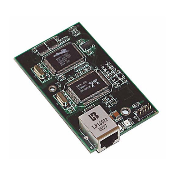
1. I & O NTRODUCTION VERVIEW The RCM2100 series is an advanced line of modules that incor- porates the powerful Rabbit 2000 ® microprocessor, flash mem- ory, static RAM and an RJ-45 Ethernet port, all on a PCB the size of a business card. Throughout this manual, the term RCM2100 refers to the complete series of RCM2100 RabbitCore modules unless other production models are referred to specifically. -
Page 6: Standard Ethernet Versions
1.1.1 Standard Ethernet Versions There are two RCM2100 models that incorporate an RJ-45 Ethernet port: RCM2100. The RCM2100 is the most fully equipped module in the family, with an Ethernet port, 512K flash memory, and 512K static RAM. The Ethernet port uses some of the Rabbit 2000 microproces- sor’s parallel ports, reducing the available number of I/O pins to 34. - Page 7 The RCM2100 modules have two 40-pin headers to which cables can be connected, or which can be plugged into matching sockets on a production device. The pinouts for these connectors are shown in Figure 1 below. PB1-CLKA PCLK BA12 BA11 BA10 VBAT VRAM...
-
Page 8: Development Software
1.2 Development Software The RCM2100 modules use the Dynamic C development environment for rapid creation and debugging of runtime applications. Dynamic C provides a complete development environment with integrated editor, compiler and source-level debugger. It interfaces directly with the target system, eliminating the need for complex and unreliable in-circuit emulators. -
Page 9: How To Use This Manual
User’s Manual. NOTE: We recommend that anyone not thoroughly familiar with Z-World controllers at least read through the rest of this manual to gain the necessary familiarity to make use of the more advanced information. - Page 10 Providing this documentation in electronic form saves an enormous amount of paper by not printing copies of manuals that users don’t need. It reduces the number of outdated manuals we have to discard from stock as well, and it makes providing a complete library of manuals an almost cost-free option.
-
Page 11: Chapter 2. Getting Started
2. G ETTING TARTED This chapter describes the RCM2100 hardware in more detail, and explains how to set up and use the accompanying prototyp- ing and development board. NOTE: This chapter (and this manual) assume that you have the RabbitCore RCM2100 Development Kit. -
Page 12: Overview Of The Prototyping Board
2.2 Overview of the Prototyping Board The Prototyping Board included in the Development Kit makes it easy to connect an RCM2100 module to a power supply and a PC workstation for development. It also pro- vides an array of basic I/O peripherals (switches and LEDs), as well as a prototyping area for more advanced hardware development. -
Page 13: Prototyping Board Features
2.2.1 Prototyping Board Features Power Connection. A 3-pin header is provided for connection of a power supply. Note that it is sym- metrical, with both outer pins connected to ground and the center pin connected to the raw V+ input. The cable of the wall transformer provided with the North American version of the Development Kit ends in a connector that is correctly connected in either orientation. -
Page 14: Prototyping Board Expansion
2.2.2 Prototyping Board Expansion The Prototyping Board comes with several unpopulated areas, which may be filled with components to suit the user’s development needs. After you have experimented with the sample programs in Chapter 4, you may wish to expand the board’s capabilities for further experimentation and development. -
Page 15: Connections
2.3 Connections There are three steps to connecting the Prototyping Board for use with Dynamic C and the sample programs: 1. Attach the RCM2100 module to the Prototyping Board. 2. Connect the programming cable between the RCM2100 module and the workstation PC. 3. -
Page 16: Attach Module To Prototyping Board
2.3.1 Attach Module to Prototyping Board Turn the RCM2100 module so that the Ethernet connector is on the left, as shown in Figure 4 below. Align the module headers J1 and J2 on the bottom side of the RCM2100 into header sockets J1 and J3 on the Prototyping Board. -
Page 17: Connect Programming Cable
NOTE: Some PCs now come equipped only with a USB port. It may be possible to use an RS-232/USB converter with the programming cable supplied with your RCM2100 module. An RS-232/USB converter is available through the Z-World Web store. Getting Started... -
Page 18: Connect Power
2.3.3 Connect Power When all other connections have been made, you can connect power to the RCM2100 Pro- totyping Board. Hook the connector from the wall transformer to header J5 on the Prototyping Board as shown in Figure 7 below. The connector may be attached either way as long as it is not offset to one side. -
Page 19: Run A Sample Program
2.4 Run a Sample Program If you already have Dynamic C installed, you are now ready to test your programming connections by running a sample program. If you are using a USB port to connect your computer to the RCM2100 module, choose and select “Use USB to Serial Converter”... -
Page 20: Where Do I Go From Here
Dynamic C TCP/IP User’s Manual, also in the online documentation set. 2.5.1 Technical Support NOTE: If you purchased your RCM2100 through a distributor or through a Z-World or Rabbit Semiconductor partner, contact the distributor or partner first for technical support. -
Page 21: Chapter 3. Software Installation & Overview
Dynamic C. for writing embedded software. It runs on an IBM-compatible PC and is designed for use with Z-World single-board computers and other single-board computers based on the Rabbit microprocessor. This chapter takes you through the installation of Dynamic C, and then provides a tour of the sample programs for the RCM2100. - Page 22 LCD display and keypad drivers. • Powerful language extensions for cooperative or preemptive multitasking • Loader utility program to load binary images into Z-World targets in the absence of Dynamic C. • Provision for customers to create their own source code libraries and augment on-line help by creating “function description”...
-
Page 23: Installing Dynamic C
3.2 Installing Dynamic C Insert the Dynamic C CD from the Development Kit in your PC’s CD-ROM drive. If the installation does not auto-start, run the program in the root directory of the setup.exe Dynamic C CD. Install any Dynamic C modules after you install Dynamic C. Dynamic C has two components that can be installed together or separately. -
Page 24: Sample Programs
3.3 Sample Programs To help familiarize you with the RCM2100 modules, several sample Dynamic C programs have been included. Loading, executing and studying these programs will give you a solid hands-on overview of the RCM2100’s capabilities, as well as a quick start with Dynamic C as an application development tool. -
Page 25: Getting To Know The Rcm2100
3.3.1 Getting to Know the RCM2100 The following sample programs can be found in the folder. SAMPLES\RCM2100 —demonstrates the setup and simple addressing to an external SRAM. • EXTSRAM.C This program first maps the external SRAM to the I/O Bank 7 register with a maximum of 15 wait states, chip select strobe (PE7), and allows writes. - Page 26 —demonstrates the use of coding with assembly instructions, cofunc- • FLASHLEDS.C tions, and costatements to flash LEDs DS2 and DS3 on the Prototyping Board on and off. LEDs DS2 and DS3 are controlled by Parallel Port A bit 0 (PA0) and Parallel Port A bit 1 (PA1).Once you have compile this program and it is running, LEDs DS2 and DS3 will flash on/off at different rates.
- Page 27 —demonstrates a simple setup for an LCD that uses the HD44780 con- • LCD_DEMO.C troller or an equivalent. Connect the LCD to the RCM2100 address and data lines on the Prototyping Board. BD0—DB0 2x20 LCD 2x20 LCD BD1—DB1 RCM2100 Prototyping Board BD2—DB2 BD0–BD7 BD0–BD7...
-
Page 28: Serial Communication
3.3.2 Serial Communication The following sample programs can be found in the folder. SAMPLES\RCM2100 Two sample programs, CORE_FLOW- CONTROL.C CORE_PARITY.C are available to illustrate RS-232 communication. To run these sample programs, you will have to add an RS-232 transceiver such as the MAX232 at location U2 and four 100 nF capacitors at C3–C6 on the Prototyping Board. -
Page 29: Other Sample Programs
Two sample programs, MASTER2.C , are available to illus- SLAVE2.C 485+ trate RS-485 master/slave communica- 681 W tion. To run these sample programs, bias you will need a second Rabbit-based termi- 220 W system with RS-485, and you will also RS-485 nation CHIP... -
Page 30: Sample Program Descriptions
3.3.4 Sample Program Descriptions 3.3.4.1 FLASHLED.C This program is about as simple as a Dynamic C application can get—the equivalent of the traditional “Hello, world!” program found in most basic programming tutorials. If you are familiar with ANSI C, you should have no trouble reading through the source code and understanding it. - Page 31 3.3.4.2 FLASHLEDS.C In addition to Dynamic C’s implementation of C-language programming for embedded systems, it supports assembly-language programming for very efficient processor-level control of the module hardware and program flow. This application is similar to , but uses assembly language for the low-level port FLASHLED.C TOGGLELEDS.C control within cofunctions, another powerful multitasking tool.
- Page 32 tion of how Dynamic C handles multitasking with costatements and cofunctions, see Chapter 5, “Multitasking with Dynamic C,” and Chapter 6, “The Virtual Driver,” in the Dynamic C User’s Manual. 3.3.4.3 TOGGLELED.C One of Dynamic C’s unique and powerful aspects is its ability to efficiently multitask using cofunctions and costatements.
-
Page 33: Upgrading Dynamic C
Dynamic C installations are designed for use with the board they are included with, and are included at no charge as part of our low-cost kits. Z-World offers add-on Dynamic C modules for purchase, including the popular µC/OS-II real-time operating system, as well as PPP, Advanced Encryption Standard (AES), and other select libraries. - Page 34 RabbitCore RCM2100...
-
Page 35: Chapter 4. Using The Tcp/Ip Features
• Two RJ-45 straight through Ethernet cables and a hub, or an RJ-45 crossover Ethernet cable. The Ethernet cables and a 10Base-T Ethernet hub are available from Z-World in a TCP/IP tool kit. More information is available at www.zworld.com. 1. Connect the AC adapter and the programming cable as shown in Chapter 2, “Getting Started.”... - Page 36 The following options require more care in address selection and testing actions, as conflicts with other users, servers and systems can occur: LAN — Connect the RCM2100’s Ethernet port to an existing LAN, preferably one to • which the development PC is already connected. You will need to obtain IP addressing information from your network administrator.
-
Page 37: Tcp/Ip Primer On Ip Addresses
4.2 TCP/IP Primer on IP Addresses Obtaining IP addresses to interact over an existing, operating, network can involve a num- ber of complications, and must usually be done with cooperation from your ISP and/or network systems administrator. For this reason, it is suggested that the user begin instead by using a direct connection between a PC and the RCM2100 board using an Ethernet crossover cable or a simple arrangement with a hub. - Page 38 Hub(s) Firewall Internet Network of Adapter Proxy Workstations Server Ethernet Ethernet RCM2100 Typical Corporate Network Board If your system administrator can give you an Ethernet cable along with its IP address, the netmask and the gateway address, then you may be able to run the sample programs with- out having to set up a direct connection between your computer and the RCM2100 board.
-
Page 39: Ip Addresses Explained
4.3 IP Addresses Explained IP (Internet Protocol) addresses are expressed as 4 decimal numbers separated by periods, for example: 216.103.126.155 10.1.1.6 Each decimal number must be between 0 and 255. The total IP address is a 32-bit number consisting of the 4 bytes expressed as shown above. A local network uses a group of adja- cent IP addresses. -
Page 40: How Ip Addresses Are Used
4.4 How IP Addresses are Used The actual hardware connection via an Ethernet uses Ethernet adapter addresses (also called MAC addresses). These are 48-bit addresses and are unique for every Ethernet adapter manufactured. In order to send a packet to another computer, given the IP address of the other computer, it is first determined if the packet needs to be sent directly to the other computer or to the gateway. -
Page 41: Dynamically Assigned Internet Addresses
4.5 Dynamically Assigned Internet Addresses In many instances, there are no fixed IP addresses. This is the case when, for example, you are assigned an IP address dynamically by your dial-up Internet service provider (ISP) or when you have a device that provides your IP addresses using the Dynamic Host Configu- ration Protocol (DHCP). -
Page 42: Placing Your Device On The Network
4.6 Placing Your Device on the Network In many corporate settings, users are isolated from the Internet by a firewall and/or a proxy server. These devices attempt to secure the company from unauthorized network traffic, and usually work by disallowing traffic that did not originate from inside the net- work. -
Page 43: Running Tcp/Ip Sample Programs
4.7 Running TCP/IP Sample Programs We have provided a number of sample programs demonstrating various uses of TCP/IP for networking embedded systems. These programs require you to connect your PC and the RCM2100 board together on the same network. This network can be a local private net- work (preferred for initial experimentation and debugging), or a connection via the Internet. -
Page 44: How To Set Ip Addresses In The Sample Programs
4.8 How to Set IP Addresses in the Sample Programs With the introduction of Dynamic C 7.30 we have taken steps to make it easier to run many of our sample programs. Instead of the and other macros, you will MY_IP_ADDRESS see a macro. -
Page 45: How To Set Up Your Computer's Ip Address For Direct Connect
4.9 How to Set Up your Computer’s IP Address for Direct Connect When your computer is connected directly to the RCM2100 board via an Ethernet connec- tion, you need to assign an IP address to your computer. To assign the PC the address with the netmask , do the following. -
Page 46: Run The Pingme.c Sample Program
4.10 Run the PINGME.C Sample Program Connect the crossover cable from your computer’s Ethernet port to the RCM2100 board’s RJ-45 Ethernet connector. Open this sample program from the SAMPLES\TCPIP\ICMP folder, compile the program, and start it running under Dynamic C. When the program starts running, the green light on the RCM2100 board should be on to indicate an Ethernet connection is made. - Page 47 Program Description For operation, network addresses must be correctly defined at the start of this program. macro in the sample program provides default settings for TCPCONFIG 1 , which is the address of the RCM2100 module, , and MY_IP_ADDRESS MY_NETMASK (which needs to be defined if you wish to ping systems outside the local MY_GATEWAY network).
-
Page 48: Sample Program: Ethcore1.C
4.11.2 Sample Program: ETHCORE1.C The RCM2100 modules with Ethernet ports can act as micro Web page servers, with dynamic interaction between the controller and the web pages. This sample program dem- onstrates how a Web page can be used to both monitor and control an RCM2100 module. Compile &... -
Page 49: Additional Sample Programs
Generally, the other defined values may be left at their default settings. If you are operat- ing the system behind a firewall or proxy and need to specify a host port for redirection, you should comment out the line reading: #define REDIRECTHOST MY_IP_ADDRESS Then uncomment the next line, which defines a specific redirection host and port: #define REDIRECTHOST "my host.com:8080"... -
Page 50: Where Do I Go From Here
4.12 Where Do I Go From Here? NOTE: If you purchased your RCM2100 through a distributor or through a Z-World or Rabbit Semiconductor partner, contact the distributor or Z-World partner first for tech- nical support. If there are any problems at this point: •... -
Page 51: Notice To Users
Specifications are based on characterization of tested sample units rather than testing over temperature and voltage of each unit. Z-World products may qualify components to operate within a range of parameters that is different from the manufacturer’s recom- mended range. - Page 52 RabbitCore RCM2100...
-
Page 53: Index
NDEX additional information hardware connections ... 11 sample programs online documentation ..5 install RCM2100 on Prototyp- getting to know the RCM2100 references ......5 ing Board ...... 12 EXTSRAM.C ....21 power supply ..... 14 FLASHLED.C ..21, 26 programming cable ... - Page 54 User’s Manual...
-
Page 55: Schematics
CHEMATICS 090-0114 RCM2100 Schematic www.rabbitsemiconductor.com/documentation/schemat/090-0114.pdf 090-0116 RCM2100 Prototyping Board Schematic www.rabbitsemiconductor.com/documentation/schemat/090-0116.pdf 090-0128 Programming Cable Schematic www.rabbitsemiconductor.com/documentation/schemat/090-0128.pdf The schematics included with the printed manual were the latest revisions available at the time the manual was last revised. The online versions of the manual contain links to the latest revised schematic on the Web site.
Need help?
Do you have a question about the RabbitCore RCM2100 Series and is the answer not in the manual?
Questions and answers