Table of Contents
Advertisement
Advertisement
Table of Contents

Related Manuals for Mercury 1st Mate


Summary of Contents for Mercury 1st Mate
- Page 1 Operation and Installation Manual...
- Page 3 Declaration of Conformity Mercury Marine declares that under our sole responsibility the following products to which this declaration relates are in conformity with the requirements of the following EU Directives: Directives 2014/35/EU The Low Voltage Directive 2014/53/EU Radio Equipment Directive (RED)
- Page 4 EU / EMEA Health & Safety (Article 3.1(a) EN 60950‑1:2006 + A11:2009 + A1:2010+ of the RED) A12:2011 + A2:2013 EN 62368‑1: 2014/A11:2017 EN 62311: 2008 EMC (Article 3.1(b) of the EN 301 489‑1 v2.2.0 RED) EN 301 489‑17 v3.2.0 EN 55032:2015 + AC:2016 EN 55024:2010 EN 61000‑3‑2:2014...
- Page 5 Fond du Lac, Wisconsin, U.S.A. Read This Manual Thoroughly IMPORTANT: If you do not understand any portion of this manual, contact the 1st Mate support team using the link provided in the Help section of this manual. Copyright and Trademark Information ©...
-
Page 7: Table Of Contents
Components The 1st Mate Hub....................1 Indicator Lights....................1 Hub Indicator Light Table..................2 1st Mate Antenna....................2 NFC Chip and RFID Sensor................2 Reset button....................... 3 Fobs........................3 Insert Battery in FOB/S..................4 Wearables......................4 Important Safety Information................5 App Download.................... -
Page 9: The 1St Mate Hub
COMPONENTS The 1st Mate Hub The 1st Mate hub is mounted in the vessel's console or in an interior compartment that is protected from the elements. NMEA network, power, and remote antenna connections are located on the hub. The 1st Mate hub is powered by battery power from the vessel's key switch circuit. -
Page 10: Hub Indicator Light Table
COMPONENTS Wireless ‑ A green light indicates that the 1st Mate wireless network is enabled. A flashing green light indicates that the wireless network is waiting to pair with a fob. Hub Indicator Light Table Indicator Off/No Waiting Status Change... -
Page 11: Reset Button
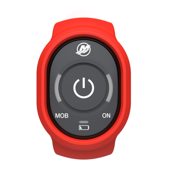
COMPONENTS Reset button The reset button located on the front of the hub can be used to reset the system after a man overboard event or to simultaneously stop all engines (hold for 3 seconds). Fobs 69454 On/Off/Reset button MOB light On light Fob battery status CAPTAIN'S FOB... -
Page 12: Insert Battery In Fob/S
COMPONENTS Insert Battery in FOB/S 1. Use a coin to turn the fob battery cover counterclockwise and remove the cover. 70936 Cover with coin slot O‑ring CR2430 battery Fob assembly 2. Install the fob battery with the + positive side of the battery facing the cover. -
Page 13: Important Safety Information
1st Mate is not a replacement for safety lanyards or personal flotation devices. App Download Download the 1st Mate app from a preferred app store and follow the instructions for new account registration. The app is required to setup the 1st Mate system. -
Page 14: Setup
• Select Horse Power rating. • Select number of engines. • Save Pair Devices Refer to the pairing instructions provided in the 1st Mate app for initial device pairing. 1. Pair each device: • 1st Mate hub • Captain's fob... -
Page 15: System Test
SETUP • Passenger fob/s 2. Accept any available device updates. System Test To test the system, go to Vessel Settings. • Test Wireless Connection • Test E‑Stop Optional Distress Messaging Distress messaging can be enabled or disabled in the App Settings menu. Open the Emergency Contacts tile located in the main menu to manually enter or import the contact information for contacts that should be notified in the event of an emergency. - Page 16 SETUP • Enable Face ID • Change TDS App PIN 2. Tap the TDS lock icon to lock or unlock the engine(s) and prevent unauthorized use. Engine RPM will be limited to idle speed when TDS is enabled. 71251 3. Turn the TDS system on or off in the App Settings menu.
-
Page 17: Features And Operation
FEATURES AND OPERATION Connecting One short beep accompanied by a green blinking fob light indicates that the fob is paired and connected. IMPORTANT: Turn on Fob Auto Connect in the fob settings menu. 1. Press the power button on the Captain's fob. •... -
Page 18: Operation
Operation 1. After boarding the vessel, firmly press the On/Off/Reset button on the Captain's fob to turn the 1st Mate system on or off. 2. Tap the Captain half of the Fob Status Icon to open the fob settings menu and adjust FOB LED Brightness. - Page 19 FEATURES AND OPERATION 5. Coordinates are only sent to emergency contacts in the form of a text message. Devices with the app that are within Bluetooth range will receive a notification from the app. 70948 Captain overboard screen If a Passenger wearing a fob falls overboard: 1.
- Page 20 FEATURES AND OPERATION 2. Tap the Cancel button and cancel the distress message after passenger recovery. 3. Tap Cancel Man Overboard. 71252 4. A man overboard event can also be canceled by pressing the power button on the Captain's fob or by pressing the On/Off/Reset on the 1st Mate Hub.
-
Page 21: App Menu
History Log ‑ TDS, battery, MOB events, and system faults are logged here. Active Notifications ‑ View active notifications, warnings, and faults. MENU LISTS Use the Menu drop down arrows to mange the 1st Mate app. My Account... - Page 22 FEATURES AND OPERATION • My Account Information • TDS PIN/Face ID • Log Out of Account My Invites • Manage invitations Vessel Settings • MOB with Gear in Neutral (ON/OFF) • Test Wireless Connection • Test E‑Stop Purchase • Order additional accessories Help Center •...
-
Page 23: Fob Light And Hub Horn Tables
FOB LIGHT AND HUB HORN TABLES Fob Light and Hub Horn Tables All blinks are 0.5 seconds long Fob Light Table Fob Light State MOB/ON Lights MOB and ON lights are illuminated red – Warning A man overboard continuous rapid blinking, alternating event has occurred sides on fob. - Page 24 FOB LIGHT AND HUB HORN TABLES Fob Light State MOB/ON Lights ON light – 1 green rapid blink, repeating Ready Continuously (2.5 second intervals) connected Indicates: Fob continuously connected to ON light – fade‑in green, followed by 1 Ready Connected green rapid blink, repeating Indicates: Fob connected to hub via auto connect or by user...
- Page 25 FOB LIGHT AND HUB HORN TABLES Fob Light State MOB/ON Lights ON light – fade‑in blue, followed by 3 red TDS Warning TDS unlocked failed blinks, repeating Indicates: user unlocked TDS from the app/VesselView or by double‑clicking the Captain's fob power button ON light –...
- Page 26 FOB LIGHT AND HUB HORN TABLES Hub Horn Mode 1 short beep Connected 71210 1 long beep TDS unlocked 71213 3 short beeps Connect failed 71211 2 beeps Disconnected 71212 3 consecutive long beeps TDS Unlock failed 71214 One long beep followed by one short TDS locked 71215...
- Page 27 FOB LIGHT AND HUB HORN TABLES Hub Horn Mode 2 consecutive short beeps at 30 second intervals Low battery 71216...
-
Page 28: Important Information
IMPORTANT INFORMATION Help Visit www.1stMate.net for product information and support. Technical Specifications General –10 –70 °C Operating temperature range (14 –158 °F) –40 –85 °C Storage temperature range (–40 –185 °F) Operating humidity range 0–100% Voltage source 13.8 V Nominal 10 mA in sleep (0.138 mW) Power consumption... -
Page 29: For Products Sold In The Us/Can
IMPORTANT INFORMATION Antenna Item Specifications Frequency Range 824–960 MHz Polarization Linear Antenna Gain 2.0 dBi (Zentih) V.S.W.R. < 2.0 Impedance 50Ω Cable RG174 Cable Length 2 Meters Mechanical Connector RP‑SMA Mounting method Magnet / 3M‑tape Operating Temperature ‑40 –85 °C (‑40 –185 °F) 10–55 Hz with 1.5 mm Environmental Vibration... - Page 30 • Consult the dealer or an experienced radio/TV technician for help. 1st Mate Hub: This device complies with FCC RF radiation exposure limits set forth for an uncontrolled environment. The antenna used for this transmitter must be installed to provide a separation distance of at least 20 cm from all persons and must not be co‑located or operating in conjunction with any other...
Need help?
Do you have a question about the 1st Mate and is the answer not in the manual?
Questions and answers