Table of Contents
Advertisement
Quick Links
Advertisement
Table of Contents

Related Manuals for RuggON VIKING MT7030

Summary of Contents for RuggON VIKING MT7030
- Page 1 VIKING Mobile Data Terminal User¡s Manual Model: MT7030 v1.1...
-
Page 2: Table Of Contents
Contents CONTENTS ............................2 SAFETY PRECAUTIONS ......................... 3 REGULATORY AND CERTIFICATION ..................... 4 FCC .............................. 4 CE M ARKING ................................. 5 ITHIUM ATTERY AFETY TATEMENT .......................... 5 CHAPTER 1. PRODUCT INTRODUCTION ..................6 ARDWARE PECIFICATIONS ..........................6 NVIRONMENT ............................... 7 I/O P ORTS ................................ -
Page 3: Safety Precautions
Safety Precautions... -
Page 4: Regulatory And Certification
Regulatory and Certification This device complies with Part 15 of the FCC Rules. Operation is subject to the following two conditions: 1. This device may not cause harmful interference. 2. This device must accept any interference received, including interference that may cause undesired operation. -
Page 5: Ce Marking
RF exposure warning This equipment must be installed and operated in accordance with provided instructions and the antenna(s) used for this transmitter must be installed to provide a separation distance of at least 20 cm from all persons and must not be co-located or operating in conjunction with any other antenna or transmitter. -
Page 6: Chapter 1. Product Introduction
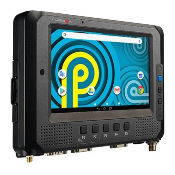
Chapter 1. Product Introduction VIKING is an in-vehicle terminal with 7¡ high resolution display and 500nits brightness, and is flexible to support a wide range of wireless connection capability. The device is well-suited for fleet management, asset management, EOBR and ELDs application. It is compliant to ISO 7637-2, SAE J1455 and SAE J1113 and its optimized power system is designed for cold cranking, load dump, transient voltage and ESD. -
Page 7: Environment
Environment Operating temperature: -20¢C (-4¢F) to 60¢C (140¢F) In accordance with MIL-STD-810H Method 501.7 High Temperature Procedure II - Operation In accordance with MIL-STD-810H Method 502.7 Low Temperature Procedure II - Operation Storage temperature: -30¢C (-22¢F) to 70 ¢C (158¢F) ... -
Page 8: I/O Ports
I/O Ports Item Description RS-232 x 1 with 0/5/12V support 0.6/0.3A (COM1) Serial RS-232 TX, RX/422/485 x 1 (COM2) USB 2.0 x 2 USB 3.1 type C x 1 Ethernet Gigabit Ethernet (RJ45 ) x 1 Digital I/O DI x 2, DO x 2 Raw CAN bus, optional SAE J1939 support Audio headset jack x 1 Audio... -
Page 9: Dimension And Weight
Dimension and Weight VIKING Standard Dimension: 219.98 x 151.98 x 40.80 (mm) / 8.66 x 5.98 x 1.61 (in.) (W x H x D) Weight: 1.25 kg/ 2.76 lbs. Front View Dimension 219.98mm 151.98mm Side View Dimension 40.80mm... -
Page 10: Package List
Package List Before you begin the installation or configuration process, make sure to inspect all the components and accessories. Contact your representative if there are any missing or damaged items. Please verify the delivery of the contents upon receipt VIKING in-vehicle terminal ... -
Page 11: Chapter 2. Hardware Installation
Chapter 2. Hardware Installation... -
Page 12: Chapter 3. Hardware Mounting
Chapter 3. Hardware Mounting The VIKING supports a standard VESA version MIS-D, 75, C (75mm distance quadrate order, M5 thread, deepness 6mm) through the four drill holes on the back side of the device. Notes: To prevent any damage or injury, make sure the mounting bracket is securely attached. -
Page 13: Chapter 4. Start Up
Chapter 4. Start up Powering the System Installation Instructions Fuses 10A are required in connecting the power cable and battery in series to avoid the risks of wire damage and vehicle burning. Please refer to the diagram below for VIKING installation. - Page 14 Connector Power VIKING allows a wide range of DC power input from 9~36V via a 5-pin M12 A-code power cord. There are two options to start up the VIKING, either via car power cable or external power adapter. Here is the 5-pin M12 A-code power cord. The wire definition Wire Color Description...
- Page 15 Power source from car power cable 1. The bare wire lead cable allows you to directly wire 12 V or 24 V car power supply. Please follow the wire definition to connect to your power source. Please refer to the installation diagram on page 17 to install the 10A fuse between the power cable and power source.
- Page 16 Power source from external power adapter If your power source is from external power adapter, it means the power source isn¡t controlled by AAC/Ignition signal. Please short red (V+) and white (ACC/ Ignition) wires. Make sure that all the power supplies are disconnected when you plug the power cord into the power connector.
-
Page 17: Led Status
LED Status The LEDs on VIKING are status indicators that show the operating status of your system. The status indicators can help pinpoint possible failed hardware components causing specific symptoms. There are two status indicators in the front panel. Refer to the description below. -
Page 18: Adjust The Speaker Volume
Adjust the Speaker Volume VIKING provides the volume control buttons to adjust the speakers¡ volume; you can also control the overall level of sound using Android Setting. When you press the top part of the volume button, it makes the volume louder; pressing the bottom part makes the volume lower ... -
Page 19: Internal Microphone
Internal Microphone VIKING is equipped with 2 internal microphones (one at the front and the other at the rear) for better audio reception, so you don¡t need an external one. In addition to the built-in speaker and microphones, you can plug external headsets in the audio jack. Programmable Buttons VIKING provides default commands for five programmable buttons. -
Page 20: Chapter 5. Jumpers And Connectors
Chapter 5. Jumpers and Connectors Bottom View DC-in GNSS (SMA Jack) DIO, CAN bus USB, RS-232/422/485 (COM2) RS-232 (COM1) -
Page 21: External Connectors Pin Assignments
External Connectors Pin Assignments Use this section as a reference for the pin assignments of the various ports available on the VIKING. Power Connector Description ACC/ Ignition Note: Please refer to section 1 in Chapter 4 for connecting the external power cable to power source.
Need help?
Do you have a question about the VIKING MT7030 and is the answer not in the manual?
Questions and answers