Table of Contents
Advertisement
Advertisement
Table of Contents

Related Manuals for Texmo Industries Taro Pumps NMH 7040


Summary of Contents for Texmo Industries Taro Pumps NMH 7040
- Page 1 Non-Clog Sewage Pumps Instruction & Operating Manual OMSP001A 2020.01...
- Page 2 OMSP001A 2020.01...
-
Page 3: Table Of Contents
Table of Contents Introduction 2. Warranty information Complying with standards 4. Contents in the packing box 5. Information about your pump 6. Schematic drawings Key product specifications & features 8. Cross-section view Pre-installation requirements 10. Installation procedures 11. Basic troubleshooting 12. -
Page 4: Introduction
1. Introduction Thank you for choosing a quality product manufactured by Texmo Industries. We request you to read this manual carefully to ensure that the system you have purchased will be operated correctly. This manual is intended to provide you with information on your product and information on installation and operation. -
Page 5: Contents In The Packing Box
4. Contents of the packing box Based on model you have purchased, your Non-clog Sewage Pump is packed along with instruction manual and warranty card in either a corrugated box or in a wooden crate. 5. Information about your pump Taro Non-clog Sewage Pumps are manufactured using Non-clog Sewage Pumps find wide application for high quality raw materials and components using... -
Page 6: Schematic Drawings
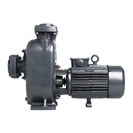
6. Schematic drawing View of a Non-clog Sewage Monoblock is shown below in Fig. 1: Fig. 1 View of Non-clog Sewage Monoblock OMSP001A 2020.01... -
Page 7: Key Product Specifications & Features
7. Key specifications & features Standard Specification of Monoblock is shown below in TABLE 1: Single Phase – 2 Pole: 1.0, 2.0 HP Phase and Power Three Phase – 2 Pole: 1.0, 2.0, 3.0 HP Three Phase – 4 Pole: 5.0 HP Motor Type Single phase : CSR Starting method... - Page 8 Product Performance Specification Product performance data are provided in TABLE 2 below: NMH SERIES - THREE PHASE NON-CLOG SEWAGE MONOBLOCKS Approximate performance values of NMH series at 415 V (-15% to +6%), 50 Hz, AC power supply Total Head Values Motor Pipe Size Model...
- Page 9 Key features: Pump The pump is designed with semi-open impeller to prevent clogging of the impellers during pumping A small clearance is maintained between the impeller blade surface and the replaceable wear plate so that high heads can be developed The pump by virtue of its design does not require a foot valve.
-
Page 10: Cross-Section View
8. Cross-section view Cross-section view of single phase Capacitor Start and Run High Speed Monoblock is shown below in Fig. 2: Fig. 2 Cross-section view of a Non-clog Sewage Monoblock – NMH 7040 / NMH 1550 27 26 PART NAME PART NAME PART NAME Deep Groove Ball Bearing... - Page 11 Cross-section view of a three-phase Non-clog Sewage Monoblock set is shown below in Fig. 3: Fig. 3 Cross-section view of a Non-clog Sewage Monoblock – NMH 2250 11 12 PART NAME PART NAME PART NAME Flange Square Rotor With Shaft Terminal Box Cover Gasket Square Support For Body...
- Page 12 Cross-section view of a three-phase Non-clog Sewage Coupled Pump is shown below in Fig. 4: Fig. 4 Cross-section view of a Non-clog Sewage coupled set 60 59 57 56 54 53 52 51 50 49 48 47 46 45 43 42 39 38 37 36 35 34 33 30 29 28 13 14...
-
Page 13: Pre-Installation Requirements
9. Pre-installation requirements Arrangement for Installation Engage a professional and trained mechanic with experience in erecting Non-clog Sewage Pumps Ensure proper safety precautions during installation Ensure that a level foundation is ready before erection of the pump. Contact the dealer from whom the pump was purchased for the motor mounting details for preparing the foundation Use appropriate lifting equipment during installation. - Page 14 If you detect damage or discrepancy in the product, contact the dealer from whom the pump was purchased Note Do not use this pump for oil or toxic, acidic, corrosive, and flammable liquids. Pumping flammable liquids could cause explosion Warning Use appropriate equipment for lifting / lowering the pump.
- Page 15 Operation Precautions The shaft of the pump passes through a gland and stuffing box arrangement. Do not attempt to run the pump dry as the sleeve / oil seal can get damaged during dry rotation. Ensure the pump is primed first and then run it Caution Switch OFF the power before working on electrical lines Warning...
-
Page 16: Installation Procedures
10. Installation procedure Please follow the below procedure to install the pump. The supply voltage should be within the specified voltage range. Water temperature for operation of the pump should not exceed 33 C. Failure to observe the precautions given above could cause the pump to malfunction and Caution may lead to current leakage or electrical shock If you find any abnormalities like vibration, noise, smell, etc. - Page 17 Fig. 5 Non-Clog Sewage Pump on a concrete foundation - installation DELIVERY FLANGE FILLING PLUG FILLING PLUG EARTH SCREWS EARTH SCREWS SUCTION FLANGE SUPPORT DRAIN PLUG DRAIN COVER FOUNDATION CONCRETE BASE CONCRETE BASE FOUNDATION BOLT & NUT BOLT & NUT (a) NMH 7040 / NMH 1550 (b) NMH 2250 FILLING PLUG...
- Page 18 Use prescribed pipe sizes as mentioned on the product name plate Place the pump centre line as close as possible to the water surface and with the free end of the suction pipe fixed above the bottom of the well. Refer Fig. 6, shown below, for recommendations: SUPPORT FOR SUCTION PIPE SUCTION PIPE...
- Page 19 Ensure that the suction pipe connected to the pump suction flange is horizontal or sloping upwards towards the pump suction flange to prevent air lock. A pipe sloping downwards towards the pump suction flange will result in air lock. Refer Fig. 8, shown below, for the preferred suction pipe orientation.
- Page 20 Electrical Installation Check the power supply voltage and frequency and compare with the product requirements specified on the nameplate Observe relevant EB regulations while providing power supply to the motor As far as possible, do not use multiple joints in the electrical cabling while connecting the starter to the pump Ground the pump using the two earth screws provided on the leg of the motor body Ensure electrical joints, if any, are properly and adequately insulated...
- Page 21 Connecting the Power Supply Observe relevant Electricity Board regulations while powering up the pumpset Caution Before inserting the power plug or connecting the wires to the terminal board, make sure the power supply is properly disconnected. Failure to do so may lead to electrical shock, short, or injury caused by the unintended starting of the pump Warning Do not use damaged cables, power plugs, or loose power outlets.
- Page 22 Fig. 9(b) Three-phase Connect three wires from the starter to the Motor Terminals marked A, B & C. Interchange any two line leads for change of direction. NMH 7040 / NMH 2250 / NCH 2250 NMH 1550 / NCS 3775 OMSP001A 2020.01...
-
Page 23: Basic Troubleshooting
11. Basic troubleshooting To prevent serious accidents, disconnect the power supply before inspecting the pump. Warning Read this Operation Manual thoroughly before requesting repair. Contact the dealer from whom this equipment was purchased. Servicing and troubleshooting must be handled by qualified persons with proper tools and equipment. Common faults, root causes for these, and suggested actions are provided in TABLE 3 below: Fault Possible causes... - Page 24 Fault Possible causes Suggested actions Low-voltage operation Operate in the recommended voltage range Wrong direction of rotation Interchange the supply connections of any two phases for three phase pumps Static suction lift high Position the pump within recommended suction lift Total head higher than specified Ensure delivery head within specified value head...
- Page 25 Fault Possible causes Suggested actions Bearings worn out Dismantle and replace worn out bearings Pump cavitating due to high Reduce static suction lift. suction lift Pump runs Pump not grouted Grout the pump rough and noisy Rotor shaft is bent resulting in Replace rotor shaft rotor rubbing against stator bore Excessive wear and tear...
- Page 26 OMSP001A 2020.01...
-
Page 27: Preventive Maintenance Checks
12. Preventive maintenance checks Precautions to be taken Disconnect power supply before starting maintenance or inspection of the pump to avoid electrical shock Warning If you find any damages or abnormalities, switch OFF the pump and report the problem to the dealer from whom the set was purchased Note NOTE: The manufacturer assumes no responsibility for damage or injury due to disassembly in the field. - Page 28 Both these data should be compared to corresponding data recorded when the unit was initially installed Any reduction in shut-off head may indicate wear of the pump hydraulics Any increase in motor current at duty flow rate indicates a possible overload condition Measure the insulation resistance of the winding to check the condition of the motor Monthly checks Priming time...
-
Page 29: Do's And Don'ts
13. Do’s and don’ts Do’s Don’ts Foot valve is not required. However, a quality foot valve Do not install the pump with high static suction lift with strainer can be used to prevent rags, leaves, etc. from being sucked into the pump and thereby clogging the pump Ensure leak proof joints on the suction side to prevent Do not use piping smaller than what is mentioned on... -
Page 30: Important Safety Instructions
14. Important safety instructions Only qualified personnel should be involved for inspection, maintenance, and/or repairs. The successful and safe operation of such a product depends on proper handling, installation, and maintenance. It is suggested that in case of non-functioning of the product, the customer is requested to contact the dealer through whom the purchase was made. -
Page 31: Storage & Handling
15. Storage & Handling The Non-clog Sewage Pumps are supplied from the factory in proper packing in which they should remain until they are to be installed The product should be stored in a closed, dry, and well-ventilated room Do not store the products under direct sunlight Handle the pumps with care and do not expose the product to unnecessary impact and shocks During unpacking and prior to installation, care must be taken while handling the pump to ensure that the product is not subjected to shock loads... -
Page 32: Company Contact Information
16. Company contact information For most up to date information on Texmo Industries, please visit www.taropumps.com OMSP001A 2020.01... - Page 33 OMSP001A 2020.01...
- Page 34 P.B.No. 5303, 1800-102-8888 Mettupalayam Road, www.taropumps.com Coimbatore - 641 029, India info@taropumps.com OMSP001A 2020.01...
Need help?
Do you have a question about the Taro Pumps NMH 7040 and is the answer not in the manual?
Questions and answers