Summary of Contents for ASL INTERCOM DANS01
- Page 1 DANS01 IP65 Dynamic Ambient Noise Sensor Installation Guide ASL Document Ref.: U-0511-0059.doc Issue: 02 complete, approved - Date: 28/10/09 Part Number: M0511_34...
- Page 2 DANS01 – Installation Guide This equipment is designed and manufactured to conform to the following EC standards: EN55103-1/E1:1996, EN55103-2/E5:1996, EN50121-4:2006, ENV50204:1995 Safety EN60065:2002 Failure to use the equipment in the manner described in the product literature will invalidate the warranty.
-
Page 3: Installation
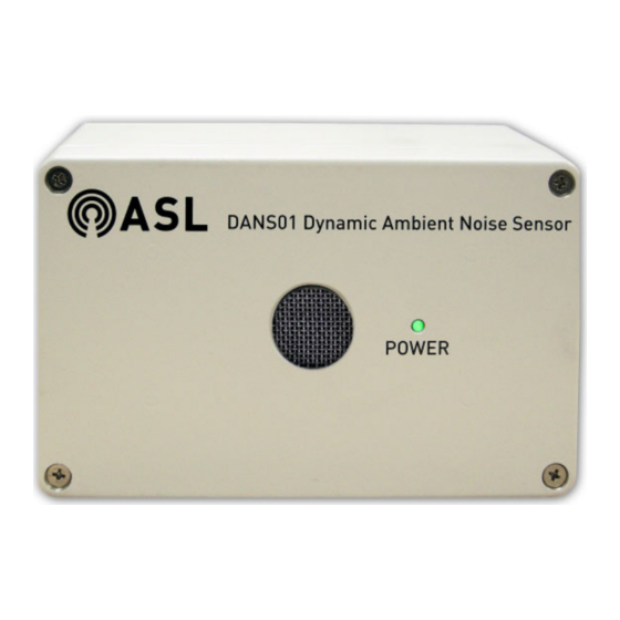
Dimensions (H x W x D) / Weight..................160 mm x 100 mm x 81 mm / 980 g Gland / Conduit Hole ..............................20 mm Front Panel POWER MICROPHONE Microphone Built-in microphone detects the ambient noise. POWER LED Green LED illuminates to indicate that the DANS01 is powered. Issue: 02 complete, approved Page 3 of 12... - Page 4 It is suggested that the fixings are pozipan head screws, with a thread length of the required fixing length plus 9 mm, as the length of the screw inside the DANS01 back box will be 9 mm. The screw heads must not be of a diameter greater than 7.5 mm, and their shafts need to be able to be passed through the holes provided for them in the DANS01 back box.
- Page 5 Remove DANS01 front panel by unscrewing the four corner fixings (4 x Philips screws). Two plastic coated steel tethers are provided to hold the front panel when the DANS01 is opened, and to provide strain relief to the wiring connecting the PCB to the terminal block on the back box. This allows the front panel to be opened for maintenance purposes without disconnecting the wiring.
- Page 6 DANS01 – Installation Guide Choose the required cable entry point or points, and remove the M20 blanking plug(s) at the chosen position(s); see Figure If rear entry is preferred, the installer may drill holes in the rear of the back box as described below.
- Page 7 Secure the back box; see fixing hole positions in Figure 4. The DANS01 should be directed towards likely sources of ambient noise e.g. areas where people congregate. It should not be placed to localised sources of noise that would be unrepresentative of the area of coverage.
- Page 8 (page for connection details, if required. Power the DANS01 on from the central equipment rack. The LED on the front panel illuminates to indicate that the unit is powered. Secure the front panel by screwing it tight to provide an IP65 seal, but not excessively tight so that any of the fixing threads are stressed, as this may cause them to weaken and shear.
-
Page 9: Connections
DANS01 – Installation Guide Connections In order to deploy DANS sensors the Terminal Signal Description Connect system should meet the following design requirements: Balanced audio output (+VE) AUDIO+ 0 dBu (nominal) / 66 Ω To Router The DANS sensors require... -
Page 10: Mechanical Dimensions
DANS01 – Installation Guide Mechanical Dimensions Figure 6 Mechanical dimensions FRONT VIEW DANS01 Dynamic Ambient Noise Sensor POWER All gland/conduit holes are 20 mm. (Glands shown as examples only.) 28 mm 23 mm 146 mm 23 mm 60 mm 28 mm... -
Page 11: Safety And Precautions
DANS01 – Installation Guide Safety and Precautions Environmental Packing for Return for Repair The temperature and humidity ranges shown in the specifications for this product must not be exceeded. All electronics assemblies must be This equipment must not be installed in an area that is... - Page 12 Service and Warranty Name and Address of Authorised Distributor: This product carries a full warranty. For full details of warranty and service agreements, please contact the Authorised Distributor who supplied the product to you. Exclusions The warranty does NOT cover: Customer misuse, including incorrect installation.


Need help?
Do you have a question about the DANS01 and is the answer not in the manual?
Questions and answers