Table of Contents
Advertisement
Quick Links
DGM-32/64-M-RLY-RF
MAINTENANCE MANUAL
Digitize, Inc.
158 Edison Road
Lake Hopatcong, New Jersey 07849
Tel: (973) 663-1011
Fax: (973) 663-4333
E-mail:
info@digitize-inc.com
Website:
http://www.digitize-inc.com
DGM-32/64
DGM-32/64-RLY
DGM32/64-RF
DGM-32/64-M-RLY
INSTALLATION
AND
Part Number: 700135-0000
Revision: O
Issue Date: 3/21
Advertisement
Table of Contents

Related Manuals for DIGITIZE DGM-32/64


Summary of Contents for DIGITIZE DGM-32/64
- Page 1 DGM-32/64 DGM-32/64-RLY DGM32/64-RF DGM-32/64-M-RLY DGM-32/64-M-RLY-RF INSTALLATION MAINTENANCE MANUAL Digitize, Inc. 158 Edison Road Lake Hopatcong, New Jersey 07849 Tel: (973) 663-1011 Part Number: 700135-0000 Fax: (973) 663-4333 Revision: O E-mail: info@digitize-inc.com Issue Date: 3/21 Website: http://www.digitize-inc.com...
- Page 2 Digitize, Inc. 158 Edison Road Lake Hopatcong, NJ 07849-2217 The Digitize logo (stylized) is a registered trademark of Digitize, Inc.
- Page 3 This manual has been prepared by DIGITIZE, INC. for use by its licensees, distributors and customers. The information contained herein is the property of DIGITIZE, INC. and may not be copied, disclosed or reproduced, in whole or in part, without the prior written approval of DIGITIZE, INC. Any unauthorized disclosure to, or use of the enclosed information by, unauthorized third persons shall void any and all representations, warranties and obligations on the part of DIGITIZE, INC.
- Page 5 FCC NOTICE In compliance with Paragraph 15.105 of the FCC Rules and Regulations, the following notice is provided. NOTE: This equipment has been tested and found to comply with the limits for a Class A digital device, pursuant to Part 15 of the FCC Rules. These limits are designed to provide reasonable protection against harmful interference when the equipment is operated in a commercial environment.
-
Page 7: Table Of Contents
Table of Contents 1 GENERAL INFORMATION ............1 SYSTEM DESCRIPTION ....................1 DGM DESCRIPTION ....................... 1 OPTIONS ......................... 2 1.3.1 32 ZONE EOL ......................2 1.3.2 RLY-8 ........................2 1.3.3 COMMUNICATIONS STYLES ................2 1.3.4 COLOR ........................3 1.3.5 EXTERNAL KEYPAD ....................3 SPECIFICATIONS ...................... - Page 8 2.9.2 WIRING........................13 2.9.3 RATINGS ....................... 14 2.10 RADIO FREQUENCY INTERFACE P/N 400605-0001 & P/N 900708-# (OPTIONAL) 14 2.10.1 GENERAL ......................14 2.10.2 WIRING........................14 2.11 FIBER OPTIC INTERFACE BOARD P/N 400506-0002 (OPTIONAL) ......14 2.11.1 GENERAL ......................14 2.11.2 WIRING........................
- Page 9 4.3.20 FUNCTION 19 (SETTING TROUBLE RELAY) ............. 32 4.3.21 FUNCTION 20 (SETTING ALARM RELAY) ............32 4.3.22 FUNCTION 21 (SETTING THE CALL OUT OPTION) .......... 33 4.3.23 FUNCTION 22 (SETTING ZONE TO NORMALLY OPEN/CLOSED) ....33 4.3.24 FUNCTION 23 (SETTING PIN NUMBERS) ............33 4.3.25 FUNCTION 24 (SETTING THE STORE EVENTS OPTION) ........
-
Page 11: General Information
1.2 DGM DESCRIPTION DIGITIZE models DGM-32, DGM-32-RLY, DGM-32-RF and DGM-32-M32-RLY are multiplex data gathering modules capable of monitoring 32 supervised input points. (See Figures 1.1, 1.2, and 1.3.) Also supervised are “AC POWER”, “TAMPER”, “GROUND”... -
Page 12: Options
DGM INSTALLATION AND MAINTENANCE MANUAL Transformer assembly Part # 900546-0000 12 Volt 12 AH battery Part # 900414-0006 * Two 32 zone input boards are required for DGM-64. One Multiplex Communication Card must be selected from the following (only one may be used per DGM): RS-422/485 Dual Line Interface card Part # 400405-0003... -
Page 13: Color
- Modem indicates communications will be via audio modem. Regardless of what style is selected, the SYSTEM 3505 Prism Lx must be equipped with the proper interface to handle the selected communications protocol. A DIGITIZE Multiplex system can mix and match any communications protocol available. 1.3.4 COLOR Each DGM is available in a choice of two colors. -
Page 14: Fuses
The inner door is hinged to allow easy removal by lifting up. The enclosure is intended for indoor use only. An optional NEMA 3R enclosure is available. 1.4.5 DIMENSIONS Refer to the table below for DGM dimensions. Table 1.1 - Dimensions DGM-32/64 DGM-32/64-RLY DGM-32/64-M-RLY HEIGHT (in.) 25.40 25.40 19.50... -
Page 15: Temperature And Humidity
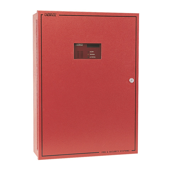
DGM INSTALLATION AND MAINTENANCE MANUAL NOTE: Weights specified are for typical units. Actual weights may vary based on the options installed on the DGM. Shipping weights may vary based on packaging methods. 1.4.7 TEMPERATURE AND HUMIDITY Operating Temperature Range - 40 to + 60 Degrees Celsius Storage Temperature Range - 40 to + 60 Degrees Celsius Operating Humidity Range... - Page 16 DGM INSTALLATION AND MAINTENANCE MANUAL Figure 1-1 - DGM-32/64 and DGM-32/64-RF 700135-0000 Rev. O...
- Page 17 DGM INSTALLATION AND MAINTENANCE MANUAL Figure 1-2 - DGM-32/64-RLY and DGM-32/64-RLY-RF Figure 1-3 - DGM-32-M-RLY/ DGM-32-M-RLY-RF 700135-0000 Rev. O...
- Page 18 DGM INSTALLATION AND MAINTENANCE MANUAL 700135-0000 Rev. O...
-
Page 19: Installation
2 INSTALLATION 2.1 HANDLING 2.1.1 PRECAUTIONS CAUTION!: Do not touch circuitry during installation. Static discharge may damage components. 2.2 UNPACKING AND INSPECTION Before opening, inspect the shipping container for unusual damage. Then, carefully unpack the unit and inspect it for scratches, dents, and loose internal components. If your inspection reveals any physical damage, retain the packing material and contact the shipping carrier immediately. -
Page 20: Mounting Instructions
DGM INSTALLATION AND MAINTENANCE MANUAL 2.3.3 MOUNTING INSTRUCTIONS The cabinet supplied with the standard model DGM is designed for surface mounting. The mounting area must be a smooth, clean surface on a permanent partition. The cabinet must be securely fastened to the mounting surface using the four mounting holes. -
Page 21: Wiring
DGM INSTALLATION AND MAINTENANCE MANUAL 2.5.2 WIRING 2.5.2.1 BS1 These terminals are respectively, the normally closed (NC), common (C), and normally open (NO) contacts of the auxiliary relay (relay 0). 2.5.2.2 CONNECTOR P0 This connector is used to interface to the 32 zone EOL and/or the RLY-8 boards via ribbon cable. -
Page 22: Rs-422/485 Interface Board P/N 400405-0003 (Std)
“T1” channel strips away the parity bit and substitutes its own parity bit. The DIGITIZE Multiplex system uses the parity bit in a forced parity mode. This conflicts with some “T1” network systems. Other uses for the RS-232 interface can be for interfacing to customer owned modem communications systems. -
Page 23: Wiring
DGM INSTALLATION AND MAINTENANCE MANUAL 2.8.2 WIRING Field wiring for this board must be tested and connected prior to assembling the rest of the unit. Connect the communications line(s), observing polarity, to the proper terminals. 2.8.2.1 Terminals TX, RX & COM These terminals are used for multiplex communications in a system utilizing RS-232 mode of communications. -
Page 24: Ratings
DGM INSTALLATION AND MAINTENANCE MANUAL 2.9.2.2 P1 This connector must be plugged into P1 of the main board of the DGM. This connector is polarized for proper installation. 2.9.3 RATINGS Maximum Circuit Voltage +-12VDC Maximum Circuit Current 50 mA Maximum Line Impedance 600 Ohm 2.10 RADIO FREQUENCY INTERFACE P/N 400605-0001 &... -
Page 25: Wiring
DGM INSTALLATION AND MAINTENANCE MANUAL 2.11.2 WIRING Field wiring for this board must be tested and connected prior to assembling the rest of the unit. Connect the communications line(s) to the proper terminals. Transmit (TX) must be connected to Receive (RX). Be sure to keep protective caps on any used terminals. -
Page 26: Zone Eol
DGM INSTALLATION AND MAINTENANCE MANUAL 2.12.3.2 P1 This connector must be plugged into P0 of the main board of the DGM. This connector is polarized for proper insertion. 2.13 32 ZONE EOL 2.13.1 GENERAL Each 32 Zone EOL card may be switch selected for zone groups of 32. A DGM-32 is supplied with one 32 Zone EOL card (expandable to two). -
Page 27: External Keypad
DGM INSTALLATION AND MAINTENANCE MANUAL 2.15 EXTERNAL KEYPAD The External Keypad is optional with the DGM-32-M-RLY and DGM-32-M-RLY-RF units. Up to 16 keypads may be used for each DGM. The keypads are primarily for Entry Zone security. 2.15.1 WIRING 2.15.1.1 Eight Position Quick Disconnect This connector must be connected to RJ11 of the main board. - Page 28 DGM INSTALLATION AND MAINTENANCE MANUAL DGM-32/64-RF Digitize Inc. 158 Edison Rd, Lake Hopatcong NJ 07849 Manual Display / Keyboard 973-663-1011 www.Digitize-Inc.com PCB PN 400373-0001 Mounted on door. – On when any zone Alarm Led LCD Display 2 Line x 16 Character in panel is in Alarm.
-
Page 29: System Initialization
3 SYSTEM INITIALIZATION 3.1 GENERAL For initial set-up of the Data Gathering Module, the following instructions should be carried out in the order in which they appear. However, if during the operation of the unit, it should become necessary to set the time on the internal clock, this can be done without going through the powerup sequence. -
Page 30: Battery Installation
DGM INSTALLATION AND MAINTENANCE MANUAL 3.4 BATTERY INSTALLATION The stand-by battery is installed on the lower shelf of the cabinet. 3.5 POWER-UP 3.5.1 AC POWER With the AC circuit breaker or local power disconnect switch in the OFF position, connect the AC power wires to the transformer input terminal strip. Then apply AC power to the DGM. -
Page 31: Programming
4 PROGRAMMING 4.1 PROGRAM INITIALIZATION Upon power-up, the DGM panel will display the program revision number. Next the panel will display the number of boards installed. Each one of the possible extra boards represents eight zones. Verify that all of the input zones on the panel are on the display. -
Page 32: Programmable Functions
DGM INSTALLATION AND MAINTENANCE MANUAL STEP 3: If the password was entered correctly, "ACCESS GRANTED" will appear on the display. Access to the programming area will be provided for 5 minutes. If the password was entered incorrectly, “ENTER PASSNUMBER” will display. 4.3 PROGRAMMABLE FUNCTIONS The following programmable functions are available on the DGM. -
Page 33: Function 0 (Setting Dgm Panel Number)
DGM INSTALLATION AND MAINTENANCE MANUAL To view or modify each function setting, enter the number of the function, followed by the FUNC button on the keypad. Or, you may scroll through the function settings by pressing the FUNC button. The first time you press FUNC, Function 0 will display. -
Page 34: Function 2 (Setting The Time )
DGM INSTALLATION AND MAINTENANCE MANUAL To view or change the First Zone Number, press “1”, FUNC or, if you are viewing the previous function, just press FUNC. The second line of the display will read “1 - 1st Zone Num.” A message will scroll on the first line: The Number assigned to the first zone in this DGM panel is 0001. -
Page 35: Function 4 (Setting To Beep On Alarm)
DGM INSTALLATION AND MAINTENANCE MANUAL To change the Passnumber, enter the new six-digit number on the keypad and press ENTER. The new Passnumber will display in the scrolling message. Press CLR/SIL to clear the display. Press FUNC to advance to the next function. 4.3.5 FUNCTION 4 (SETTING TO BEEP ON ALARM) This function selects whether or not the beeper will sound when an alarm is initiated on any of the inputs. -
Page 36: Function 6 (Set Tamper/Tilt Sensitivity)
DGM INSTALLATION AND MAINTENANCE MANUAL 4.3.7 FUNCTION 6 (SET TAMPER/TILT SENSITIVITY) This function sets the sensitivity of the Tamper/Tilt switch. Tamper/Tilt is a combination of two switches in parallel. One switch is the door open switch. The other switch is a mercury tilt switch. A value of 1 is the most sensitive, while a value of 254 is the least sensitive. -
Page 37: Function 9 (Setting Telegraph On / Off Ratio)
DGM INSTALLATION AND MAINTENANCE MANUAL the scrolling message, zero represents 1/8 second, one represents 2/8 seconds, etc. The highest acceptable value is 31, which represents 32/8, or four seconds. Press CLR/SIL to clear the display. Press FUNC to advance to the next function. 4.3.10 FUNCTION 9 (SETTING TELEGRAPH ON / OFF RATIO) During a telegraph transmission, a set of contacts are opening and closing to transmit the telegraph message over the wire. -
Page 38: Function 11 (Setting Request To Send Timing)
DGM INSTALLATION AND MAINTENANCE MANUAL indicated in the scrolling message, one represents 300 baud, two represents 600 baud, etc. The highest acceptable value is four, which represents 2400 baud. Press CLR/SIL to clear the display. Press FUNC to advance to the next function. 4.3.12 FUNCTION 11 (SETTING REQUEST TO SEND TIMING) Note: This function is automatically downloaded from the SYSTEM 3505... -
Page 39: Function 13 (Setting Zones To Bypass During Day Mode)
DGM INSTALLATION AND MAINTENANCE MANUAL To select the desired zone enter the zone number, then press READ, or press READ to advance sequentially through the zones. Enter the new delay for the specific zone, then press ENTER. If you wish to change all zones to the same delay, enter the new delay within any zone, then press IN/OUT. -
Page 40: Function 15 (Setting Global Command Response)
DGM INSTALLATION AND MAINTENANCE MANUAL To view or change Function 14, press “14”, FUNC or, if you are viewing the previous function, just press FUNC. The second line of the display will read “14 - Set Format.” A message will scroll on the first line: The Multiplex Format is Enabled. -
Page 41: Function 17 (Setting Open / Closed Telegraph Index)
DGM INSTALLATION AND MAINTENANCE MANUAL To view or change Function 16, press “16”, then FUNC or, if you are viewing the previous function, just press FUNC. The second line of the display will read “16 - Burg Panel.” A message will scroll on the first line: The Burg/Panel option is Disabled. -
Page 42: Function 19 (Setting Trouble Relay)
DGM INSTALLATION AND MAINTENANCE MANUAL Function 23 (Set Pin Number) 1111 Function 24 (Store Events Option) Disabled Function 25 (Backporch) 5 Milliseconds Function 26 (AC Delay) 16 Seconds Function 27 (Pin Length) Function 28 (Activate KP) All Off Function 29 (Assign Add 2N) No Zones to Follow Function 30 (Link Down Delay) 16 Seconds... -
Page 43: Function 21 (Setting The Call Out Option)
DGM INSTALLATION AND MAINTENANCE MANUAL Press TGGL to enable/disable the Alarm Relay. Press CLR/SIL to clear the display. Press FUNC to advance to the next function. Note: This function must be disabled when any of the other Trouble Relay or Telegraph Output options are selected. -
Page 44: Function 24 (Setting The Store Events Option)
DGM INSTALLATION AND MAINTENANCE MANUAL The passnumber you entered does not give you access to this function. Press CLR/SIL to clear display or FUNC to view next Function. Enter the four-digit PIN number, then press ENTER. To change all PIN numbers to the same number, enter the new setting within any zone, then press IN/OUT. -
Page 45: Function 27 (Pin Length)
Press CLR/SIL to clear the display. Press FUNC to advance to the next function. 4.3.29 FUNCTION 28 (ACTIVATE KEYPAD) This function allows the use of a DIGITIZE, INC. Keypad Part No. 400492-0001. After installing the keypad, select the address of the keypad and the zone to which it will be assigned. -
Page 46: Function 29 (Additional Zones)
DGM INSTALLATION AND MAINTENANCE MANUAL 4.3.30 FUNCTION 29 (ADDITIONAL ZONES) This function allows you to program additional zones to follow the keypad zone status. This is useful if you have infrared detectors or motion sensors within a keypad detected zone. By using the keypad for entrance, the DGM will automatically disable reporting the interior zones when the keypad zone is disarmed. -
Page 47: Function 32 (Erase All Pins)
DGM INSTALLATION AND MAINTENANCE MANUAL 4.3.33 FUNCTION 32 (ERASE ALL PINS) This function will erase all stored PINS that have been programmed if a keypad has been installed. To view or change Function 32, press “32”, then press FUNC or, if you are viewing the previous function, just press FUNC. -
Page 48: Function 36 (Disable Trouble Led)
DGM INSTALLATION AND MAINTENANCE MANUAL Display External Keypad Status is Disabled. Press TGGL button to change. Press CLR/SIL to clear display or FUNC to view next Function. Press CLR/SIL to clear the display. Press FUNC to advance to the next function. 4.3.37 FUNCTION 36 (DISABLE TROUBLE LED) This function allows the user to set the TROUBLE LED on the DGM to turn on for zones that are bypassed. -
Page 49: Theory Of Operation
5 THEORY OF OPERATION 5.1 GENERAL When the front panel door is closed and the key lock is engaged, you can view the LCD display and LED indicators through the Plexiglas window in the door. During normal operation, the DGM displays the current time. In the event of an alarm the DGM displays, in order, each zone number, its status and any fault conditions. -
Page 50: Panel Controls
DGM INSTALLATION AND MAINTENANCE MANUAL Send) value. These are the only two functions that can be accessed without having a valid passnumber entered. 5.2 PANEL CONTROLS The following is a list of the controls located on the front panel of the DGM. Numerical buttons are for entering information such as time, zone numbers, and function numbers. -
Page 51: Tggl (Used Only For Programming Functions)
DGM INSTALLATION AND MAINTENANCE MANUAL The ENTER button is also used by programming functions to accept information entered from the keypad. 5.2.5 TGGL (used only for Programming Functions) Press the TGGL button to alternate between function settings that have only two options. For example, the TGGL button will alternately turn On/Off Expanded Multiplex Format (Function 14). -
Page 52: Led Indicators
DGM INSTALLATION AND MAINTENANCE MANUAL 5.3.1.3 LOW BATT The Low Batt message will be displayed if the battery voltage falls to 10.5 VDC. When the voltage goes above the value, the message will disappear. 5.3.1.4 BATTERY FAULT The Battery Fault message will be displayed if the battery is not connected. 5.3.1.5 GROUND DETECT If a ground should be detected on any of the zone inputs, the GROUND DETECT message will display. -
Page 53: Operating Procedure
DGM INSTALLATION AND MAINTENANCE MANUAL 5.4 OPERATING PROCEDURE 5.4.1 GENERAL In the event that a zone changes from SECURE to ALARM status, an LCD message will indicate the zone number in alarm, and the ALARM LED will light. The zone information will also be sent to the SYSTEM 3505 PRISM LX on the next polling cycle. -
Page 54: External Keypad Indicators
DGM INSTALLATION AND MAINTENANCE MANUAL Each keypad is assigned an Entry Zone, which is any zone on the DGM panel. The keypad is then able to ARM or DISARM. It is possible to assign any or all (16) keypads to the same Entry Zone. - Page 55 DGM INSTALLATION AND MAINTENANCE MANUAL the Entry Delay Zone and any controlled zone are not secured. When all assigned zones are secured, the GREEN LED will once again be on steadily. Once all zones are secured, enter a valid PIN number. The GREEN LED will turn off, the RED LED will turn on, and the beeper will remain off.
- Page 56 DGM INSTALLATION AND MAINTENANCE MANUAL 700135-0000 Rev. O...
-
Page 57: Testing
All system functions should be tested based on a period indicated by the NFPA guideline. In no event shall this period exceed once every three months to insure proper system operation. If any malfunctions occur, contact your local authorized DIGITIZE, INC. distributor for qualified service. - Page 58 DGM INSTALLATION AND MAINTENANCE MANUAL Table 6.1 - System Test FUNCTION/ZONE ALARM TROUBLE FUNCTION/ZONE ALARM TROUBLE FUNCTION/ZONE ALARM TROUBLE FUNCTION/ZONE ALARM TROUBLE FUNCTION/ZONE ALARM TROUBLE FUNCTION/ZONE ALARM TROUBLE FUNCTION/ZONE ALARM TROUBLE FUNCTION/ZONE ALARM TROUBLE 700135-0000 Rev. O...
- Page 59 Digitize by telephone or in writing. Buyer will prepay all freight charges to return any products to the repair facility designated by Digitize and include the RMA number on the shipping container. Digitize will, at its option, either repair the defective products or parts or deliver replacements for defective products or parts on an exchange basis to Buyer, freight prepaid to the Buyer.
Need help?
Do you have a question about the DGM-32/64 and is the answer not in the manual?
Questions and answers