Advertisement
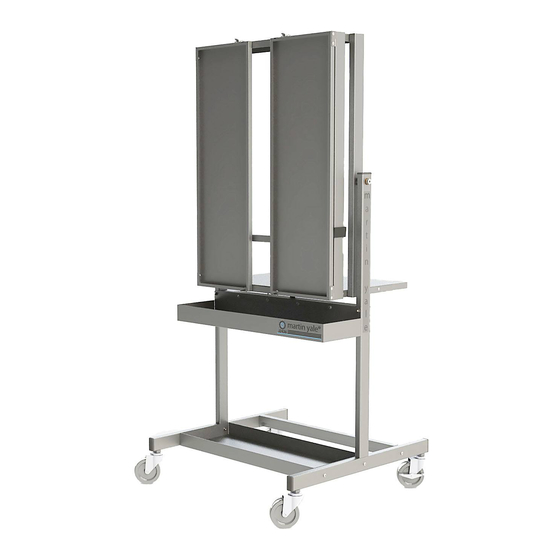
Martin Yale Titan
1.0
Introduction
Thank you for selecting the Martin Yale Titan – THE Professional Padding Press. We recommend that you
familiarize yourself with the Titan Padding Press by carefully reading these instructions.
understanding of the information contained within these instructions will help to eliminate most operator
associated errors and ensure years of trouble-free performance.
2.0
Assembly
2.1
Base Assembly
2.1.1 Refer to Parts List A and Diagram A. Locate Hardware Box and the large parts for
the Base Assembly. Open Hardware Box, remove casters and bag A. Set bags B
and C aside for now. Open bag A.
2.1.2 Attach Base Tray and Base Support to T-Frames as shown with "martin yale" decals
facing outward using the six (6) medium-length bolts, (6) lock washers and (6) acorn
nuts; tighten bolts.
2.1.3 Insert the four (4) short bolts through the four (4) middle holes in Drip Tray and Tilt
Latch Assembly as shown, then install four (4) keps nuts; tighten bolts.
2.1.4 Note orientation of Drip Tray and Tilt Latch Assembly. Carefully slide Drip Tray/Tilt
Latch Assembly over the T-Frames and align four (4) outer holes. Insert four (4) long
bolts as shown, install (4) lock washers and (4) acorn nuts; tighten bolts.
2.1.5 Install casters as shown by carefully laying the base assembly on its side. Each T-
Frame should have one (1) locking caster and one (1) non-locking caster.
2.2
Upper Assembly
2.2.1 Refer to Parts List B and Diagram B. Locate Bag B, the L-Frames and the Bottom
Panel. Open parts bag B.
ATTENTION! Note the orientation of the L-Frames in Diagram B. Failure to install the
2.2.2 Install each L-Frame individually using shoulder bolt and nylon washer in the
orientation shown; tighten shoulder bolt using hex-key wrench.
2.2.3 Position Bottom Panel in the orientation shown, noting the location of notches on
front. Loosely install six (6) screws with six (6) keps nuts. Before tightening, position
Upper Assembly upright and verify Tilt Latch locks into place. This will result in an
audible click, and the assembly will no longer tilt. Tighten screws.
ATTENTION! Be careful after removal of the L-Frame Shipping Braces to not bend or
2.2.4 Remove (2) screws securing each L-Frame Shipping Braces at top of each L-Frame.
Discard screws and braces.
2.2.5 Carefully slide one (1) clamp onto each L-Frame as shown, ensuring clamp is
installed onto front tube. Do not bend L-Frames!
M-S027946
ProSource Packaging, Inc.
14911 Stuebner Airline Suite A
Houston, TX 77069
800-203-0233
www.Machine-Solution.com
L-Frames in the proper orientation will cause the unit to not function
properly.
otherwise damage the L-Frames.
Model J2436
Thorough
Rev. 2 8/15/14
Advertisement
Table of Contents

Related Manuals for Martin Yale Titan

Summary of Contents for Martin Yale Titan
- Page 1 Martin Yale Titan Model J2436 Introduction Thank you for selecting the Martin Yale Titan – THE Professional Padding Press. We recommend that you familiarize yourself with the Titan Padding Press by carefully reading these instructions. Thorough understanding of the information contained within these instructions will help to eliminate most operator associated errors and ensure years of trouble-free performance.
- Page 2 For Carbonless Paper The Titan is constructed so that the Clamp Bar can be set on the edge of the paper for little penetration or moved away from the edge so that carbonless padding compound can penetrate further into the sheets.
- Page 3 Parts List A Item # Part # Qty. Description W-O243615 T-Frame W-O243617 Base Support W-O243619 Base Tray W-O243621 Drip Tray W-O243623 Tilt Latch Assembly M-S001062 Short Bolt (¼-20 X 5/8) M-S001548 Mid-Length Bolt (¼-20 X 1.25) M-S001547 Long Bolt (¼-20 X 2.25) M-S008029 Lock Washer (¼...
- Page 4 Parts List B Item # Part # Qty. Description W-O243637 Right L-Frame W-O243639 Left L-Frame W-O243657 Bottom Panel M-S003140 Shoulder Bolt (.50 X 2.00) M-S008100 Nylon Washer (.503 ID) M-S001022 Screw (10-32 X 3/8) M-S007008 Keps Nut (10-32) Parts Diagram B...
- Page 5 Parts List C Item # Part # Qty. Description W-O243649 Clamp W-O243663 Top Panel Assembly W-O243669 Right Door W-O243669 Left Door W-O243675 Clamp Bar M-S036011 Right Hinge M-S036010 Left Hinge M-S001022 Screw (10-32 X 3/8) M-S007008 Keps Nut (10-32) M-S043744 End Cap Parts Diagram C...
Need help?
Do you have a question about the Titan and is the answer not in the manual?
Questions and answers