
Subscribe to Our Youtube Channel
Related Manuals for Everyway Comfy Stim

Summary of Contents for Everyway Comfy Stim
- Page 1 INSTRUCTION MANUAL INSTRUCTION MANUAL INSTRUCTION MANUAL FOR THE Comfy Stim Digital Combination Unit Distributed by: 2460 Read Before Use Aug. 2019 V1.5 Model No.: EV-806...
-
Page 2: Table Of Contents
INDEX Chapter Contents Page General Description ..........2 Introduction ...............2 Cautions ..............4 Warnings ..............6 Contraindications ............7 Adverse Reactions ............7 Construction ..............8 8. Technical Specifications ...........10 Replacement Parts ............14 10 Accessories ...............14 11. Graphic Symbols ............15 12. Operating Instructions ..........15 13. Parameter Controls ...........16 14. -
Page 3: General Description
The pain message travels from the injured area along the small The Comfy Stim is a battery operated pulse generator that sends nerves leading to the spinal cord. Here the message is switched to electrical impulses electrodes to the body and reach the nerves and different nerves that travel up the spinal cord to the brain. -
Page 4: Cautions
John Faraday in 1831. Through the square wave pattern it is able to work directly on muscle motor neurons. The Comfy Stim has 3. Patients with an implanted electronic device, such as a cardiac pacemaker, implanted defibrillator, or any other metallic or electronic... -
Page 5: Warnings
2. Safety of powered muscle stimulators for use during pregnancy the contractions may be strong enough to close the airway or has not been established. cause difficulty in breathing. 3. Caution should be used for patients with suspected or diagnosed 4. -
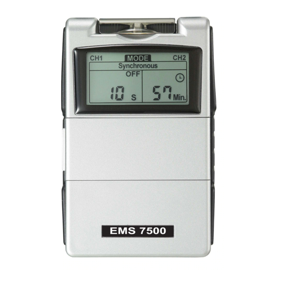
Page 6: Construction
Chapter 7 : CONSTRUCTION BACK SIDE BACK (9) BATTERY STRIP (10) BATTERY CASE FRONT (11) BELT CLIP (1) LEAD CONNECTOR (2) INTENSITY CONTROL (OUTPUT ON/OFF SWITCH) SIDE (3) PANEL COVER (12) PROTECTIVE COVER (4) LIQUID CRYSTAL DISPLAY (5) MODE CONTROL (6) SET CONTROL (7) INCREMENT CONTROL (8) DECREMENT CONTROL... -
Page 7: Technical Specifications
Chapter 8 : TECHNICAL SPECIFICATIONS in a cycle pattern. The pulse width is decreased by 50% from its original setting The technical specification details of Comfy Stim are as follows: in 0.5 second, then the pulse rate is MECHANISM TECHNICAL DESCRIPTION... - Page 8 The waveforms of the TENS modes are as follows. “Ramp Up” and “Ramp Down” time. 1. Burst Therefore, the setting of ON Time should be no less than two times of the “Ramp” time in this mode. ON TIME ≥ Ramp up + Ramp down 20 Alternate Mode The stimulation of the CH2 will occur after the 1st contraction of CH1 is completed.
-
Page 9: Accessories
The label attached to the back of device contains important infor- mation abou t this device - model name,serial number(started with The replaceable parts and accessories of Comfy Stim devices are manufacturing year and week of the device), supply voltage, name as given below –... -
Page 10: Parameter Controls
3) Open the electrode package. Then insert each lead wire pin into binations of point and contiguous electrode placements, the quicker the pig tail of the electrodes pulse rates are suggested. 4) Place the electrode on your body as directed by your physician. Despite above recommendations, these individual patients may re- 5) Slowly turn on the device by rotating the Intensity control quire slight variations of the above settings, according to the nature... - Page 11 muscle stimulator in the circumstances to quickly break the spasm. OUTPUT MODE Use a quick pulse rate, wide pulse duration and set the intensity to The output of both channels are adjustable. It can be in the pat- visible contraction (still within patient tolerance). Twenty or thirty tern of synchronous or alternate.
-
Page 12: Lead Wire Maintenance
Chapter 15: LEAD WIRE MAINTENANCE Chapter 18: TIPS FOR SKIN CARE Clean the wires by wiping with a damp cloth. Coating them lightly To avoid skin irritation, especially if you have sensitive skin, follow with talcum powder will reduce tangling and prolong life. these suggestions: 1. -
Page 13: Adjusting The Controls
Chapter 20 : ADJUSTING THE CONTROLS Removal 1. Turn off the unit prior to removing the electrodes. 1. Panel Cover: 2. Lift at the edge of electrodes and peel; do not pull on the lead A lid covers the controls for selecting mode and adjusting settings. wires because it may damage the electrodes. - Page 14 3. Lead Connector Connection of the electrodes is made with the two-lead connector 8. Timer (lead wires). The device must be switched off before connecting The unit has a timer of 1-60 minutes and Continuous. It can be the cables. Both intensity controls must be at the Off position. adjusted by pressing the “Set”...
- Page 15 c. Set Pulse Width 11. Steps to Set a EMS Program Pulse Width is adjustable from 50 us to 300 us. Press “SET” The settings can be adjusted according to the following steps. control to enter this menu, then press “Increment” or “Decrement” f.
- Page 16 i. Set On Time l. Set Pulse Rate Pulse rate is adjustable from 2Hz to 150 Hz . Press “SET” The On Time controls the time of stimulation. By pressing the control to enter this menu, then press “Increment” or “Set”...
-
Page 17: Battery Information
Check & Delete Accumulative Record RECHARGEABLE BATTERIES(NOT INCLUDED) At the individual records menu, press “Mode” control to switch Prior to the use of a new unit, the rechargeable battery should be to accumulative record menu. Press the “SET” control first, then charged according to the battery manufacturer’s instructions. -
Page 18: Safety-Technical Controls
3. Do not submerge the device in liquids or expose it to large amounts of water. Should any malfunctions occur while using the Comfy Stim , check 4. Return the device to the carrying box with sponge foam to ensure that the unit is well-protected before transportation. - Page 19 Chapter 27: ELECTROMAGNETIC COMPATIBILITY Chapter 26 : WARRANTY INFORMATION All Comfy Stim models carry a warranty of one year from the The device complies with current specifications with regard to elec- date of delivery. The warranty applies to the stimulator only and cov- tromagnetic compatibility and is suitable for use in all premises, ers both parts and labor relating thereto.
- Page 20 Guidance and manufacturer’s declaration - electromagnetic immunity Guidance and manufacturer’s declaration - electromagnetic immunity The unit is intended for use in the electromagnetic environment specified The unit is intended for use in the electromagnetic environment below. The customer or the user of the unit should assure that it is used in specified below.
- Page 21 (Appendix I) Test Environment Recommended separation distances between portable and mobile RF communications equipment and the unit The unit is intended for use in an electromagnetic environment in which radiated RF disturbances are controlled. The customer or the user of the unit can help prevent electromagnetic interference by maintaining a mini- mum distance between portable and mobile RF communications equipment (transmitters) and the unit as recommended below, according to the maxi-...
- Page 22 (Appendix II) Waveform of EV-806 Digital TENS/EMS 2. N MODE(Normal): Load: 500 ohm Pulse Rate: 150Hz TENS Pulse Width: 300µs 1. B Mode(Burst) Load: 500 ohm Scope A : Pulse Rate: 150Hz Pulse Width: 300µs VERT:10.0V/DIV HORIZ:2mS Scope A : OUTPUT:59.1825V pk-pk Pulse Rate:148.8Hz VERT:10.0V/DIV...
- Page 23 3. M MODE (-50% Pulse Width & Rate Modulation): 3. SD1 MODE (-40% Pulse Width & Intensity Modulation): Load : 500 ohm Load : 500 ohm Pulse Rate : 150Hz Pulse Rate : 150Hz Pulse Width : 300µs Pulse Width : 300µs Scope A : Scope A : VERT:10.0V/DIV...
- Page 24 4. SD2 MODE (-70% Pulse Width & Intensity Modulation): Load : 500 ohm 1. S MODE (Synchronous): Pulse Rate : 150Hz Load: 500 ohm Pulse Width : 300µs Pulse Rate: 150Hz Pulse Width: 300µs Scope A : Contraction Time:12 Sec Relation Time:12 Sec VERT:10.0V/DIV Ramp Time:6 Sec...
- Page 25 2. A Mode(Alternate) Load:500ohm Pulse Rate:150Hz Pulse Width:300µs Contraction Time:12 Sec Relation Time:12 Sec Ramp Time:6 Sec...
Need help?
Do you have a question about the Comfy Stim and is the answer not in the manual?
Questions and answers