Table of Contents
Advertisement
Quick Links
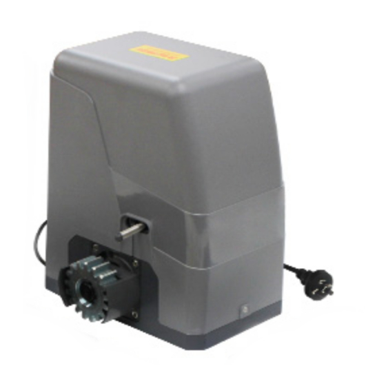
Sliding Gate Opener
User Manual GTR061
Please Note: This motor runs on AC Power as standard but can also be operated by DC Battery Backup or Solar Power.
Gate in closed position
Gate in open position
Viewed from inside the property
TECHNICAL SUPPORT
Instructions must be read before beginning installation. Please follow these instructions carefully,
incorrect installation could affect gate operation. If you require more information, please contact
your local Richmond Wheel & Castor Co branch.
For installation or troubleshooting assistance visit richmondau.com/gate-motor-support/
AU: 03 9070 5713
NZ: 0800 61 71 81
International: +613 9551 2233
GTR061 Installation Manual: Rev 3
1
Advertisement
Table of Contents

Related Manuals for Richmond GTR061

Summary of Contents for Richmond GTR061
- Page 1 Instructions must be read before beginning installation. Please follow these instructions carefully, incorrect installation could affect gate operation. If you require more information, please contact your local Richmond Wheel & Castor Co branch. For installation or troubleshooting assistance visit richmondau.com/gate-motor-support/...
- Page 2 Please contact your nearest authorised dealer for compatible solar panels in your state/region. Please refer to the relevant manual for each accessory for instructions on wiring them to the GTR061 gate motor. GTR061 Installation Manual: Rev 3...
-
Page 3: Table Of Contents
Connecting Battery Backup (sold separately) Connecting Solar Power (sold separately) Troubleshooting Clearing and Pairing Remotes Additional Drawings and Diagrams Maintenance For accessories: please refer to the relevant accessory manuals for instructions on wiring them to the GTR061 motor. GTR061 Installation Manual: Rev 3... -
Page 4: Gate Opening Default Setting Information
Left-Hand Opening: Motor mounted on the Fig 2 left-hand side Any works done to the motor must be completed whilst the power is off and the motor is unplugged GTR061 Installation Manual: Rev 3... -
Page 5: General Safety
Any other use not specified in this documentation could damage the product and be dangerous. • Only use original parts for any maintenance or repair operation. Richmond Wheel & Castor Co declines all responsibility with respect to the automation safety and correct operation when other supplier’s components are used. -
Page 6: Parts List
Limit travel stops (left hand & right hand) Limit switch mounting plate screws M6X18 M12 x 100mm masonry anchor bolts (Drill bit size: M12 masonry) Motor mounting set screws M10 x 50mm, spring & fl at washers GTR061 Installation Manual: Rev 3... -
Page 7: Technical Specifications
Limit switch Spring limit switch Noise Up to 58dB Working duty S2, 20min (20 minutes continuous operation) IP Rating IP54 Maximum Remote Controls to be paired Frequency 433.92 MHz Working temperature -20°C ~ +70°C Fig 03 GTR061 Installation Manual: Rev 3... -
Page 8: Motor Installation Before You Start
Motor Installation: Before you start • The GTR061 Sliding Gate Motor is suitable for powering the opening and closing motion of gates up to 800kg in weight, and up to a length of 8m on level, flat ground. • Gate motion is achieved by the rotating cog of the gate motor driving the gear rack fitted to the moving gate (sold separately). -
Page 9: Tools Required / Example Sliding Gate Setup
Gate Track and Gate End Gate Guide Gate Track Wheels Catch Rollers Stopper If you require any gate hardware, contact Richmond Wheel & Castor Co or an authorised reseller. GTR061 Installation Manual: Rev 3... -
Page 10: Step 1 - Gate Preparation
IS PROHIBITED. BREAK SHARP DIMENSIONS ARE IN MILLIMETERS EDGES TOLERANCES TO 0.25MM Gate on an incline/decline FILE LOCATION: \\Dataserver\sys4\db\dave\sketches\Gate parts\GTR1 56 set up\ For installation on sloping surfaces contact Richmond to discuss a suitable motor option GTR061 Installation Manual: Rev 3... -
Page 11: Step 2 - Motor Pad Footing
Fig 5 Fig 6 Once the gate has been placed onto the gate motor the gate must move back and forth freely at all times when in manual release mode GTR061 Installation Manual: Rev 3... -
Page 12: Step 4 - Drilling Holes For Anchor Bolts
Fig 11 Fig 12 Fig 13 Fig 14 Once the gate has been placed onto the gate motor the gate must move back and forth freely at all times when in manual release mode GTR061 Installation Manual: Rev 3... -
Page 13: Step 6 - Gear Rack & Motor Alignment
To put the gate motor into manual mode, insert the In manual mode, the gear can turn freely key and open the manual release bar as shown and the gate can be operated by hand Fig 17 GTR061 Installation Manual: Rev 3... - Page 14 At this stage of final assembly, the cover is removed (not shown) and the power cable is still unplugged. Fig 18 GTR061 Installation Manual: Rev 3...
-
Page 15: Step 7 - Limit Travel Stops
The installation of spring limit switch block is shown in Figure 20 Fig 20 Spring Limit Switch Gear Rack Limit This diagram Travel shows the gate Stop in the open GTR061 Motor position Motor Gear Mounting Plate Fig 21 GTR061 Installation Manual: Rev 3... - Page 16 Once satisfi ed the gate is opening and closing to the test limit switch position. Set the limit travel stop positions in place (see Step 8 and Step 9 for instructions on powering the motor and testing the limit switch positions). GTR061 Installation Manual: Rev 3...
-
Page 17: Step 8 - Powering The Motor
Press the remote control again and the gate will close. • Soft start/soft stop function - The GTR061 is set by default to provide the soft start/soft stop function. We recommend this default position is always maintained. Your motor is now set up for basic remote control operation. To set further... -
Page 18: Step 9 - Testing The Limit Travel Stops
To Reset: When setting new limit travel stop positions please ensure that you turn the power off and then on again. Turning the power off will reset the limit travel stop memory, allowing for new limit travel stop positions to be recognised by the motor. GTR061 Installation Manual: Rev 3... - Page 19 Fuse holder 24VDC BAT Terminal Richmond Fuse Part Number: 5GTR156SP002 Generic Fuse Part Number: F10AL250V Fig 25 See next page for more details. Please refer to page 24 and 25 for added description of the terminals GTR061 Installation Manual: Rev 3...
- Page 20 Generic Part Number F10AL250V Fuse Type Glass Ferrule (3AG) Fuse Speed Fast Acting Amps Voltage 250vAC Length 20mm Fig 26 Diameter 6.35mm Please refer to page 24 and 25 for added description of the terminals GTR061 Installation Manual: Rev 3...
- Page 21 Transformer Power Input Connection: WARNING: Do not touch 240V AC. All works to mains power must be conducted by a licensed electrician F5AC250V Fuse (5mm dia x 20mm long glass cartridge fuse) Fig 27 GTR061 Installation Manual: Rev 3...
-
Page 22: Dip Switch Adjustment
OFF - Disabled Default position is ON (do not change) Infrared Detection Delay When Closing ON – Infrared detection delay is set to 1 second OFF – Infrared detection delay is disabled Default position is OFF GTR061 Installation Manual: Rev 3... -
Page 23: Further Settings And Programming
1 person). For safety we strongly reccommend that stall force mode is left Enabled (dip switch 7 is at the on position) do not switch dip switch 7 to the off postion. GTR061 Installation Manual: Rev 3... - Page 24 Ensure that power is off before completing any wiring Using a screwdriver, loosen the screw insert the wire into Tighten with a screwdriver to secure the on the side of the terminal. the terminal wire in place. GTR061 Installation Manual: Rev 3...
- Page 25 Circuit board connection for low voltage power supply BAT Terminal: Battery Backup Terminal J4 (MOT) Terminal: Factory Fitted (pre-wired) DC motor wire connection (Red wire to top,black wire to bottom). J8 Terminal: 24V DC warning light connection GTR061 Installation Manual: Rev 3...
-
Page 26: Battery/Solar Connection
To install battery backup, refer to the Fig 28 below. Connect the pre-stripped black and red wires to the BAT terminal of the GTR061 circuit board and then connect to your GTR206 battery backup pack using the GTR206 battery 2-pin plug supplied. -
Page 27: Connecting Solar Power (Sold Separately)
GTR205 solar battery pack using the 2-pin plug supplied. Lastly, connect the solar panel to the battery pack using the 2-pin plug supplied BAT - BAT - BAT + BAT + Fig 29 GTR061 Installation Manual: Rev 3... -
Page 28: Troubleshooting
3. Remove the obstacle. 3. Gate meets obstacle. For support or assistance with troubleshooting, visit richmondau.com/gate-motor-support/ Or ring your local Richmond Wheel & Castor Branch AU: 03 9070 5713 NZ: 0800 61 71 81 International: +613 9551 2233 GTR061 Installation Manual: Rev 3... -
Page 29: Clearing And Pairing Remotes
NZ: 0800 61 71 81 International: +613 9551 2233 Richmond Wheel & Castor Co declines all responsibility for any consequences resulting from improper use of the product, or use which is different from that expected and specified in the present documentation. -
Page 30: Additional Drawings And Diagrams
• Check and tighten anchor bolts • Check for loose and corroded wires. • Ensure your gate can still move smoothly by hand by placing the gate into manual mode using the manual release key. GTR061 Installation Manual: Rev 3...
Need help?
Do you have a question about the GTR061 and is the answer not in the manual?
Questions and answers