
Subscribe to Our Youtube Channel
Summary of Contents for CENTURION SYSTEMS i5
- Page 1 INDUCTIVE LOOP DETECTOR I5 INFRARED BEAMS/PHOTOCELLS POCKET INSTALLATION GUIDE Centurion Systems (Pty) Ltd Centurion Systems (Pty) Ltd www.centsys.com...
-
Page 2: Safety Instructions
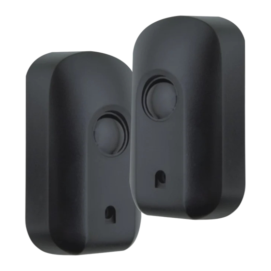
1. Introduction The i5 infrared beams are designed to provide optimum safety by detecting the presence of a person or vehicle traversing the path of a moving gate or door. The beams can be interfaced with most automation equipment. They can... -
Page 3: Operation
Please take special note of critical aspects that MUST be adhered to in order to prevent injury 4. Operation The i5 infrared beam/photocells consists of a transmitter and receiver unit mounted on opposite sides of an entrance. The transmitter sends a modulated infrared beam to the receiver module. -
Page 4: Installation
6.Installation The first step when installing the i5 infrared beams/photocells is to obtain maximum alignment. The transmitter and receiver are typically mounted directly opposite one another, but some leeway is given in the form of a wide beam being cast should... - Page 5 Screw-hole cover Fastener Cover Unclip screw-hole cover piece. Unscrew cover retaining fastener. Lift off cover. Unclip PCB and remove. Place self-adhesive pads onto back of enclosure Self-adhesive pads Enclosure back...
-
Page 6: Wiring Route
“O” Ring Mark position of unit. Use 5mm masonry bit to drill hole in wall. Rawl plug Mount using fastener Height - typically 750mm Fastener provided. above the ground Wiring Route Option 1: External wire 10a. Route the cables through the cable cut-out as shown in the illustration providing 12-24 V... -
Page 7: Pcb Connections
PCB connections It is very important to align the transmitter and the receiver beams. Under certain conditions (distance >10m) it may be necessary to fit the cover to achieve alignment NT72C-S10 Receiver Relay 11. Terminate wires on to the receiver PCBs prior to clipping back into enclosure as shown in the... - Page 8 Transmitter INPUT 12. Terminate wires on VOLTAGE to the transmitter 12V - 30V AC OR DC PCBs prior to clipping back into enclosure as shown in the wiring diagram. Green 13. Replace the cover and screw back the fastener and the POWER screw-hole cover.
- Page 9 All product and brand names in this document that are accompanied by the ® symbol are registered trademarks in South Africa and/or other countries, in favour of Centurion Systems (Pty) Ltd, South Africa. The CENTURION and CENTSYS logos, all product and brand names in this document that are accompanied by the TM symbol are trademarks of Centurion Systems (Pty) Ltd, in South Africa and other territories;...
Need help?
Do you have a question about the i5 and is the answer not in the manual?
Questions and answers