
Related Manuals for Robopac COMPACTA S4


Summary of Contents for Robopac COMPACTA S4
- Page 1 COMPACTA S4-S6 SUSPENSION PACK serial n° GB USE AND MAINTENANCE MANUAL “TRANSLATION OF THE ORIGINAL INSTRUCTIONS” ROTATING RING BAND WRAPPING MACHINE 3710309827 Instructions manual code English Edition 0/0213...
- Page 3 (Richtlijn 2006/42/EG bijlage II type A) ROBOPAC S.p.A. dichiara che la macchina per uso artigianale ROBOPAC S.p.A. verklaart dat de machine die bedoeld is voor e industriale, identificabile dai riferimenti in calce, è conforme ai ambachtelijke en industriële omgevingen met de hierbij requisiti essenziali di sicurezza e di tutela della salute come vermelde identificatiegegevens voldoet aan de essentiële...
- Page 4 (Directiva 2006/42/CE anexa tip A) ROBOPAC S.p.A. declară că maşina pentru uz artizanal şi A ROBOPAC S.p.A. kijelenti, hogy a kisipari és ipari használatra szolgáló, a lap alján lévő hivatkozások alapján azonosítható industrial, identificabilă de referinţele din josul paginii, este în conformitate cu cerinţele esenţiale de siguranţă...
- Page 5 For purchased components and parts, ROBOPAC S.p.A. offers the user the same warranty conditions ROBOPAC S.p.A., in its fial judgement, will decide that the company obtains from the suppliers of the whether to replace the defective part or request it to aforementioned components and/or parts.
- Page 7 La rete di distribuzione ROBOPAC è, da questo momento, al vostro ser- Het distributienet van ROBOPAC is U vanaf dit moment van dienst voor elk vizio per qualunque problema di assistenza tecnica, parti di ricambio e probleem met betrekking tot technische hulp, reserve-onderdelen en voor per qualunque nuova esigenza che possa far sviluppare la vostra attività.
- Page 8 údržbu. J su r c b ir firmas ROBOPAC izpl t t ju t kls, kuru J s var siet Distribu ná siet’ spolo nosti ROBOPAC je odteraz k Vašim službám pre izmantot, lai sa emtu nepieciešamu tehnisko pal dz bu, rezerves da as akýko vek problém, o sa týka technického servisu, náhradných dielov a...
-
Page 9: Table Of Contents
taBle OF cOntents GenerAl infOrMATiOn 4.7. PneUmatic cOnnectiOns ....37 4.8. electRical cOnnectiOn ..... 38 1.1. PURPOse OF the manUal ....... 3 1.2. manUFactUReR and machine identiFicatiOn .......... 4 infOrMATiOn On AdjuSTMenTS 1.3. teRms and deFinitiOns ......5 5.1. RecOmmendatiOns FOR adjUstments ......... - Page 10 taBle OF cOntents 9.2. Film cUtting Blade RePlacement .. 72 9.3. veRtical ROlls RePlacement ..73 9.4. list OF essential sPaRe PaRts..74 9.5. machine disPOsal and scRaPing ..74 enClOSed dOCuMenTATiOn 10.1. PneUmatic ciRcUit diagRam 7370305438 ..........75 English - 2 - - 2 -...
-
Page 11: General Information
Chapter GENERAL INFORMATION 1.1. PURPOSE OF THE MANUAL – The manual is an integral part of the machine and is aimed to provide the operator the instructions for use in order to prevent and reduce the risks that arise from man-machine interface. The information have been written by the manufacturer into Italian (the original language) in full compliance with the professional writing principles and the regulations in force. -
Page 12: Manufacturer And Machine Identification
Chapter 1 GENERAL INFORMATION 1.2. MANUFACTURER AND MACHINE IDENTIFICATION The illustrated identification plate is applied directly on the machine. It contains references and indispensable operating safety indications. A) Machine model B) Machine’s serial number C) Year of manufacture D) Mains voltage E) Mains frequency F) Number of phases G) Absorption... -
Page 13: Terms And Definitions
chapter 1 geneRal inFORmatiOn 1.3. TerMS And definiTiOnS some recurring terms found within the manual are described in order to provide a more complete image of their meanings. – routine maintenance: group of functions necessary to maintain suitable machine operations and efficiency. normally the manufacturer, who defines the necessary skills and intervention procedures, plans these operations. -
Page 14: Attached Documentation
chapter 1 geneRal inFORmatiOn 1.5. ATTAChed dOCuMenTATiOn the machine is provided with the documentation listed below, in the absence of a different trade agreement. – wiring diagram and list of components. – a hard copy of the “Use and maintenance instructions” in the language of the country of use. -
Page 15: Safety Information
chapter saFety inFORmatiOn 2.1. GenerAl SAfeTy PreCAuTiOnS Carefully read the “Instructions for use” specified in the manual and – those applied directly to the machine. it is important to dedicate a little time to read the “instructions for use” in order to minimise the risks and avoid unpleasant accidents. –... -
Page 16: Safety Warnings For Handling And Installation
chapter 2 saFety inFORmatiOn 2.2. SAfeTy wArninGS fOr hAndlinG And inSTAllATiOn – the personnel authorised to handle the machine (loading and unloading) must possess particular expertise in the field of intervention. – handle (load and unload) the machine according to the instructions affixed directly to the machine, to the package and those in the user manual. -
Page 17: Safety Warnings For Use And Operation
chapter 2 saFety inFORmatiOn – the operator must test the machine and check, through a general test, that the machine can be commissioned without any risk for the operator. – dismantle all the packaging components in compliance with the standards in force in the country of installation. non compliance with the instructions given may cause risks for safety and health of the persons and economic damages. -
Page 18: Safety Warnings Related To Incorrect Use
chapter 2 saFety inFORmatiOn 2.4. SAfeTy wArninGS relATed TO inCOrreCT uSe incorrect use that can be reasonably expected – the predictable incorrect use consists of: “the use of the machine different from the indications given in the manual, that may stem from the easily predictable human behaviour”. - Page 19 chapter 2 saFety inFORmatiOn – neveR carry out an intervention with the machine enabled but Only after having stopped it properly, under safety conditions. – dO nOt clean or wash the machine with aggressive products to avoid damaging the components. –...
-
Page 20: Safety Warnings On Residual Risks
Chapter 2 SAFETY INFORMATION 2.5. SAFETY WARNINGS ON RESIDUAL RISKS When designing and building the machine, the manufacturer has paid particular attention to the RESIDUAL RISKS that may affect the safety and health of the operators. The residual risks are: “all the risks that persists although all safety solutions have been applied and integrated during machine design”. -
Page 21: Safety Warnings For Regulations And Maintenance
chapter 2 saFety inFORmatiOn 2.6. SAfeTy wArninGS fOr reGulATiOnS And MAinTenAnCe Keep the machinery in maximum efficiency condition and perform – all the scheduled maintenance operations provided for by the manufacturer. Proper maintenance will provide the best performance, a longer life span and constant compliance with safety requirements. -
Page 22: Information And Safety Signals
Chapter 2 SAFETY INFORMATION 2.7. INFORMATION AND SAFETY SIGNALS The figure indicates the position of the safety and information signs affixed to the machine. For each sign is specified the relative description. A) Electrical hazard sign Electrical shock danger: do not access within elements under tension. B) Information sign It shows the insertion points for the lifting forks. -
Page 23: Technical Information
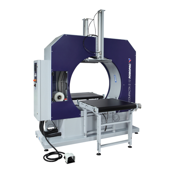
Chapter TECHNICAL INFORMATION 3.1. MACHINE GENERAL DESCRIPTION This machine is a rotating ring wrapper for the spiral wrapping of products of various shapes and sizes located on a support Readily available reel of stretch film are used for wrapping. Wrapping is performed by combining stretch film reel rotation with the horizontal movement of the product. - Page 24 During the operating stages just one operator is necessary to perform the infeed, cycle start and wrapped product outfeed operations. According to the different operating requirements, this machine can be supplied in different models and configurations. Machine Coil Compacta S4 Compacta S6 - 16 - English...
-
Page 25: Description Of The Operation Cycle
Chapter 3 TECHNICAL INFORMATION 3.2. DESCRIPTION OF THE OPERATION CYCLE Preliminary machine settings Before selecting the wrapping cycle type to be performed, you must adjust the width of the vertical rolls based on the side of the product using the following procedure. 1. - Page 26 Chapter 3 TECHNICAL INFORMATION “Total” wrapping Position the sheet of cardboard used during the machine preparation phase on the input roller table, engaging the first pair of vertical rolls. Set the product on the cardboard sheet and press the "Start" button from the control panel to initiate the work cycle.
- Page 27 Chapter 3 TECHNICAL INFORMATION Phase 3 – The advancing product uncovers photocell (B1), the "tail positioning" timer starts counting. – When the timer expires the outfeed roller conveyor stops, the “head and tail revolution” count starts; the tail part of the product is wrapped while the clamp advances to fasten film at the last revolution of the rotating ring.
- Page 28 Chapter 3 TECHNICAL INFORMATION “Head - tail” wrapping Position the sheet of cardboard used during the machine preparation phase on the input roller table, engaging the first pair of vertical rolls. Set the product on the cardboard sheet and press the "Start" button from the control panel to initiate the work cycle.
- Page 29 Chapter 3 TECHNICAL INFORMATION Phase 2 – Infeed/outfeed conveyors starts. – The advancing product uncovers photocell (B1), ring rotation starts. – After having counted one revolution, the "tail positioning" timer starts counting. – When the timer expires the outfeed roller conveyor stops, the “head and tail revolution”...
- Page 30 Chapter 3 TECHNICAL INFORMATION “Complete” wrapping and “central bands” Position the sheet of cardboard used during the machine preparation phase on the input roller table, engaging the first pair of vertical rolls. Set the product on the cardboard sheet and press the "Start" button from the control panel to initiate the work cycle.
- Page 31 Chapter 3 TECHNICAL INFORMATION Phase 3 – The “central bands” timer starts counting; at count completed, the conveyor stops, the rotating ring starts and counts the “reinforcing revolutions” set; the product is wrapped for the number of reinforcing revolutions set. Note: The number of central bands is determined by the “central bands”...
- Page 32 Chapter 3 TECHNICAL INFORMATION “Head-tail” and “central belts” wrapping Position the sheet of cardboard used during the machine preparation phase on the input roller table, engaging the first pair of vertical rolls. Set the product on the cardboard sheet and press the "Start" button from the control panel to initiate the work cycle.
- Page 33 Chapter 3 TECHNICAL INFORMATION Phase 2 – Infeed/outfeed conveyors starts. – The “central bands” timer starts counting; at count completed, the conveyor stops, the rotating ring starts and counts the “reinforcing revolutions” set; the product is wrapped for the number of reinforcing revolutions set.
-
Page 34: Safety Device Descriptions
Chapter 3 TECHNICAL INFORMATION 3.3. SAFETY DEVICE DESCRIPTIONS The figure shows the positioning of the devices on board of the machine. A) Main switch cuts off the power supply to the machine and can be locked to prevent use by unauthorised people. B) Emergency buttons when pressed they immediately stop the machine in the emergency conditions. -
Page 35: Description Of The Electrical Devices
Chapter 3 TECHNICAL INFORMATION 3.4. DESCRIPTION OF THE ELECTRICAL DEVICES The figure shows the positioning of the devices on board of the machine. A) Photocell (B1) detects product presence on the infeed conveyor. B) Sensor Detects the clamp in the “back” position. -
Page 36: Technical Specifications
For best quality results, the production cross section should be as close as possible to the machine diameter. Compacta S4 Suspension pack [mm] Worktable height: 805 mm Minimum vertical roll opening (Minimum workable cardboard width) - Page 37 Maximum vertical roll opening - Short pieces option (Maximum workable cardboard width) Maximum vertical roll opening - Standard (Maximum workable cardboard width) Description Units of Value measurement Compacta S4-S6 Compacta S4-S6 Machine Suspension pack short Suspension pack STD pieces OPT...
- Page 38 Chapter 3 TECHNICAL INFORMATION Machine dimensions Description Units of Value measurement Compacta S4 Compacta S6 Machine Suspension pack Suspension pack 1791 1799 1258 1462 1350 1544 - 30 - English...
- Page 39 Chapter 3 TECHNICAL INFORMATION Film Description Units of Value measurement Compacta S4 Compacta S6 Machine Suspension pack Suspension pack d Optional 50/125 Thickness µm 17-50 Solenoid valves Solenoid valve Y1: Controls clamp opening and closing. - 31 - - 31 -...
-
Page 40: Surrounding Areas
Chapter 3 TECHNICAL INFORMATION 3.7. SURROUNDING AREAS A) Operator station: loading and cycle start area B) Sorrounding area. C) Product outfeed area D) Lateral guide adjustment area. These areas must be suitably sized to the product being processed. 3.8. NOISE LEVEL While working, the machine reaches the noise levels shown in the table. -
Page 41: Installation Environment Characteristics
Chapter 3 TECHNICAL INFORMATION 3.9. INSTALLATION ENVIRONMENT CHARACTERISTICS Careful consideration must be given to the place where the machine is to be installed, in order to ensure that it may be easily operated, without creating any unnecessary risks for personnel. Therefore we suggest the following prerequisites: –... -
Page 42: Information On Handling And Installation Operations
Chapter INFORMATION ON HANDLING AND INSTALLATION OPERATIONS 4.1. RECOMMENDATIONS FOR HANDLING AND LOADING Important Accomplish handling and loading according to the instructions supplied by the manufacturer to be found on the machine and in the operating instructions. The person authorized to accomplish these operations must, if necessary, organise a “safety plan”... -
Page 43: Transport And Handling
Chapter 4 INFORMATION ON HANDLING AND INSTALLATION OPERATIONS 4.3. TRANSPORT AND HANDLING Transport, also according to the destination, can be performed by different vehicles. The diagram represents the most popular solutions. During transport, with the purpose to avoid sudden movements, adequately anchor the machinery to the means of transportation. - Page 44 Chapter 4 INFORMATION ON HANDLING AND INSTALLATION OPERATIONS How to carry out the standard assembly Danger Warning Authorised technical service personnel must perform installation and assembly operations. Proceed as indicated. 1. Remove the screws that block the machine to the wooden pallet. 2.
-
Page 45: Recommendations For Connections
Chapter 4 INFORMATION ON HANDLING AND INSTALLATION OPERATIONS 4.6. RECOMMENDATIONS FOR CONNECTIONS Important The connections must be made in accordance with the specifications supplied by the manufacturer in the enclosed diagrams. The person authorized to carry out said operation must posses the skills and experience acquired and acknowledged in the specific sector, must perform the connection workmanlike and keep into account all the statutory and legislation requirements. -
Page 46: Electrical Connection
Chapter 4 INFORMATION ON HANDLING AND INSTALLATION OPERATIONS 4.8. ELECTRICAL CONNECTION Standard models work with a mains voltage of: – 400 V 3Ph+N 50/60 Hz Proceed as follows for electrical connections. 1. Check that the mains voltage (V) and frequency (Hz) correspond to those of the machine (see identification plate and wiring diagram). -
Page 47: Information On Adjustments
Chapter INFORMATION ON ADJUSTMENTS 5.1. RECOMMENDATIONS FOR ADJUSTMENTS – Before performing any operation, the authorised operator must make sure that he/she understood the “Instructions for use”. – Pay attention to the SAFETY WARNINGS, do not use the machine for UNSPECIFIED PURPOSES and assess the possible RESIDUAL RISKS. -
Page 48: Friction Adjustment On Reel Carriage
Chapter 5 INFORMATION ON ADJUSTMENTS 5.3. FRICTION ADJUSTMENT ON REEL CARRIAGE Owing to the effect of the spool’s inertia, the spool carriage clutch avoids that it unwinds too much film during the cycle respect to the necessary quantity. The optimum adjustment must be performed with the heaviest spool available, that is, the one with greater inertia, and must guarantee that the... -
Page 49: Film Tension Adjustment
Chapter 5 INFORMATION ON ADJUSTMENTS 5.4. FILM TENSION ADJUSTMENT 1. Display the main page. 2. Touch the key (A) to access the manual movements (see paragraph 6.3. “Display in operation”-“Description of control panel manual controls ”). 3. Touch the wheel (B) key to enable it and then the “reel”... -
Page 50: About The Use
Chapter ABOUT THE USE 6.1. RECOMMENDATIONS FOR OPERATION AND USE – Before performing any operation, the operator must make sure that he/she understood the “Instructions for use”. – When using the machine for the first time, the operator must read the manual and identify the controls and simulate some operations, especially the start-up and shutdown. -
Page 51: Control Description
Chapter 6 ABOUT THE USE 6.2. CONTROL DESCRIPTION IG) General switch Turns the power supply on and off. Position 0 (OFF) indicates that the machine is not powered. Position I (ON) indicates that the machine is on. A) Emergency button Immediately cuts off the power supply in emergency situations stopping the machine. -
Page 52: Display In Operation
chapter 6 aBOUt the Use 6.3. diSPlAy in OPerATiOn the operative panel is a screen that lets the user set working parametres and check all machine operating condition. it is equipped with a display allowing to activate all the various functions simply by “touching” what is written on it. - Page 53 Chapter 6 ABOUT THE USE Using the panel Switching on the machine the introduction page is displayed. It contains: – Manufacturer’s name. – Type of machine. – Press the “Reset” button. 1 PRODUCT 01 – Machine ready; the main page is being displayed. –...
- Page 54 Chapter 6 ABOUT THE USE – Choose the recipe (the type of processing desired) by touching one of the keys and confirm it by touching the (B) key (to compose the recipe, see 6.5. “Cycle parameter setting”). The machine is ready to run in automatic mode all the cycle parameters displayed on the main screen.
- Page 55 3. Enter the password (1111) assigned to machine (B1) Manager. B1)Machine manager (department head). B2)Assistance service (reseller). B3)Software manager (Robopac). Once the operator has been changed and confirmed, the (A) key icon on the main page will be replaced by that assigned to the operator confirmed.
- Page 56 Chapter 6 ABOUT THE USE 3. If it is correct, confirm by touching key (F), confirm again in the pop- up window by touching key (G). Default password reset If you need to restore the default password in case you have forgotten the password set or for other reasons, proceed as indicated: 1.
- Page 57 Chapter 6 ABOUT THE USE Software settings and displays By touching the key (C) from the main page, it is possible to: 1) Set the backlighting time of the display. 2) Enable / disable the sound by pressing the keys. 3) Display information on machine status for assistance purposes.
- Page 58 Chapter 6 ABOUT THE USE Date and time setting For this operation proceed in the following way: 1. Display the main page (see 6.3. “Display in operation”-“Main page”). 2. Touch the key (A) and access via password, as machine manager (see 6.3.
- Page 59 Chapter 6 ABOUT THE USE Description of control panel manual controls Manual controls are to be used to individually operate the machine moving parts, in case of service or control before the automatic cycle start-up. By touching the key (A) on the main page, you can access the manual movements.
-
Page 60: Modification Mode Regarding The Settings
Chapter 6 ABOUT THE USE 6.4. MODIFICATION MODE REGARDING THE SETTINGS. – Written editings and values – Progressive regulation of values Important The performed modifications become instantly operative and stored automatically Written editings and values The keypad is displayed each time the editable or programmable functions are enabled. -
Page 61: Cycle Parameter Setting (Recipe Composition)
Chapter 6 ABOUT THE USE 6.5. CYCLE PARAMETER SETTING (RECIPE COMPOSITION) For this operation proceed in the following way: 1. Display the main page (see 6.3. “Display in operation”-“Main page”). 2. Touch the key (A) and access via password, as machine manager (see 6.3. - Page 62 Chapter 6 ABOUT THE USE C) Rotating ring speed function To increase or decrease rotating ring speed; this speeds up or slows down the process and reduces or increase film wrap overlaps respectively. D) Conveyor speed function Increases or decreases speed of the infeed and outfeed conveyors; this allows to speed up or slow down operation and to respectively decrease or increase film overlapping.
- Page 63 Chapter 6 ABOUT THE USE The parameters of the wrapping cycle are the following: F) Number of wraps (varying from 1 to 9): Allows you to set the number of additional revolutions to be carried out at the beginning of the wrapping cycle (product head), at the end of the wrapping (product tail) and, if necessary, the central bands.
-
Page 64: Wrapping Cycle Reset
Chapter 6 ABOUT THE USE 6.6. WRAPPING CYCLE RESET If the machine is shut down or turned off during product wrapping, the START pedal can be used to restart wrapping from where it was interrupted by pressing the START pedal again. If you wish to interrupt the wrapping cycle and start a new one, press the Stop button (A) and then the Reset... -
Page 65: Machine Operation Preparation
Chapter 6 ABOUT THE USE 6.8. MACHINE OPERATION PREPARATION Perform the adjustments for operations: – Inlet and outlet roller conveyor height (è “Information on adjustments”). – Roller conveyor position (è “Information on adjustments”). – Guide width (è “Information on adjustments”). –... - Page 66 Chapter 6 ABOUT THE USE Film spool loading 1. Display the main page. 2. Touch the key (A) to access the manual movements (see 6.3. “Display in operation”-“Description of control panel manual controls”). 3. Touch the wheel (B) key to enable it and then the “reel”...
- Page 67 Chapter 6 ABOUT THE USE 5. Load the spool on the support as illustrated in the diagram; the dotted line indicates the adhesive side of the film (interior or exterior). Unwind the film out of the protection ring. Important The adhesive side of the film must always face the product to be wrapped.
- Page 68 Chapter 6 ABOUT THE USE 8. Press the “Home” (F) key to return to the main page and to align the machine. Insert the film in the clamp For this operation proceed in the following way: 1. Display the main page. 2.
-
Page 69: Cycle Start
Chapter 6 ABOUT THE USE 5. Keep the film corner tensioned with your right hand and use the left hand to touch the key “A”. 6. The clamping unit is retracted, locking and cutting the film. 6.10. CYCLE START Proceed as indicated. 1. -
Page 70: Types Of Stopping And Starting
Chapter 6 ABOUT THE USE 6.11. TYPES OF STOPPING AND STARTING During operation there can be voluntary or unforeseen conditions that stop the machine. These are the possibilities: – Temporary stop (voluntary) – Electric black-out stop – Production end stop –... - Page 71 Chapter 6 ABOUT THE USE Production end stop This situation verifies when the work shift or machine use is over or when the machine remains inactive or not attended to for a certain lapse of time. 1. Turn main switch in pos. 0. Emergency stop Press the EMERGENCY button.
-
Page 72: Maintenance Information
Chapter MAINTENANCE INFORMATION 7.1. MAINTENANCE INSTRUCTIONS – Before performing any operation, the authorised operator must make sure that he/she understood the “Instructions for use”. – Pay attention to the SAFETY WARNINGS, do not use the machine for UNSPECIFIED PURPOSES and assess the possible RESIDUAL RISKS . -
Page 73: Maintenance Period Table
Chapter 7 MAINTENANCE INFORMATION 7.2. MAINTENANCE PERIOD TABLE Important Keep the machine in maximum working conditions by performing the programmed maintenance operations advised by the manufacturer. Good maintenance achieves the best machine performance, longer machine life and constant observance of the safety regulations. -
Page 74: Condensate Discharge
Chapter 7 MAINTENANCE INFORMATION 7.3. CONDENSATE DISCHARGE Proceed as indicated. 1. Close the tap (A) and control the level of condensation in the container (B). 2. Unscrew, if necessary, the valve (C) to empty condensation. 3. Push the valve (C) up until all condensation is removed. 4. -
Page 75: Rotating Ring Belt - Adjustment
Chapter 7 MAINTENANCE INFORMATION 7.6. ROTATING RING BELT - ADJUSTMENT Proceed as indicated. 1. Loosen the fastening screws (A) of the gear-box. 2. Use screws (B) to achieve correct belt tension. 3. Tighten the reducer fastening screws (A) when finished. Important To avoid transmission overload, do not excessively tighten the belt. -
Page 76: Machine Cleaning
Chapter 7 MAINTENANCE INFORMATION 7.8. MACHINE CLEANING General cleaning of the machine is fundamental to guarantee efficiency in the long run. All the machine must be kept free from dust, dirt and foreign bodies. The chromed shafts must be cleaned with a cloth and slightly lubricated with a cloth soaked in Vaseline oil. -
Page 77: Troubleshooting
Chapter TROUBLESHOOTING 8.1. SOME SUGGESTIONS ON OPERATION The following is some trouble shooting that might occur during operation and its solution. Inconvenient Remedy Film is too loose during the wrapping operation Increase the braking effect of the clutched roller Film is too tensed during the wrapping operation Reduce the braking effect of the clutched roller Film overlaps too little on the product Decrease conveyors’... -
Page 78: Alarm Messages
Chapter 8 TROUBLESHOOTING 8.2. ALARM MESSAGES In the event of a breakdown during operations the machine stops automatically and alarm messages appear on the display. The table lists the displayed messages, the type of problem, the cause and possible solutions. Important For these operations a precise technical skill or ability is required;... - Page 79 Chapter 8 TROUBLESHOOTING Alarm Inconvenient Cause Remedy “Clamp forward” Clamp cylinder magnetic Check and replace the sensor if alarm sensors not properly working necessary “Film rupture” The film has broken or reel is Insert the film or replace reel alarm empty Contact the technical assistance “Start Pedal”...
-
Page 80: Spare Parts Replacement Information
Chapter SPARE PARTS REPLACEMENT INFORMATION 9.1. RECOMMENDATIONS FOR REPLACING PARTS – Carry out the interventions with all the safety devices enabled and wear the DPI provided. – DO NOT carry out any intervention that is not described in the manual but contact an Assistance Service authorised by the manufacturer. -
Page 81: Vertical Rolls Replacement
Chapter 9 SPARE PARTS REPLACEMENT INFORMATION 9.3. VERTICAL ROLLS REPLACEMENT 1. Remove the guard (A) removing the 2 screws (B) and the ball joint (C). 2. Remove snap ring (D). 3. Remove the guard (E). 4. Loosen the screws (F) and loosen the chain to disengage the rolls (G). -
Page 82: List Of Essential Spare Parts
Chapter 9 SPARE PARTS REPLACEMENT INFORMATION 9.4. LIST OF ESSENTIAL SPARE PARTS List of the spare parts of easy wear and of which it would be necessary to have available to avoid long operation stops of the machine. For ordering, contact your local Dealer and refer to the spare parts catalogue. –... -
Page 83: Enclosed Documentation
Chapter 10 ENCLOSED DOCUMENTATION 10.1. PNEUMATIC CIRCUIT DIAGRAM 7370305438 A) Filter/regulator unit B) Solenoid valve C) Open/close clamp pneumatic cylinder - 75 - - 75 - English... - Page 84 chapter 10 enclOsed dOcUmentatiOn Page deliberately empty English - 76 -...
Need help?
Do you have a question about the COMPACTA S4 and is the answer not in the manual?
Questions and answers