Table of Contents
Advertisement
Quick Links
Advertisement
Table of Contents

Related Manuals for Newport LDX-3200 Series

Summary of Contents for Newport LDX-3200 Series
- Page 1 User’s Guide Precision Current Source LDX-3200 Series 70028204 March 2021...
-
Page 3: Table Of Contents
Tilt-Foot Adjustment ..........3 03_21 LDX-3200 Series... - Page 4 LDX-3200 Series Specifications ........
- Page 5 Command Refeence LDX-3200 Series Command Summary ......35 LDX-3200 Series Device-Dependent Commands ..... . 39 LDX-3200 Series Command Reference .
- Page 6 T A B L E O F C O N T E N T S LDX-3200 Series...
-
Page 7: List Of Figures
Figure 1.1 LDX-3200 Series Front Panel ..... . 4 Figure 1.2 LDX-3200 Series Rear Panel ..... . 5 Figure 2.1 Common Laser Cathode - Photodiode Cathode . - Page 8 L I S T O F F I G U R E S LDX-3200 Series...
-
Page 9: List Of Tables
Table 1.1 LDX-3200 Series Specifications1..... 6 Table 1.2 LDX-3200 Series Accessories ..... . . 8 Table 2.1 LDX-3200 Default Settings. - Page 10 L I S T O F T A B L E S viii LDX-3200 Series...
-
Page 11: Safety And Warranty Information
• Failure to perform intended measurements or functions If necessary, return the instrument to ILX Lightwave, or authorized local ILX Lightwave distributor, for service or repair to ensure that safety features are maintained (see the contact information on page xiii). 03_21 LDX-3200 Series ... -
Page 12: Safety Symbols
• Maximum Relative Humidity: <80% RH, non-condensing • Operating temperature range of 0°C to 40°C • Storage and transportation temperature of -40°C to 70°C • Maximum altitude: 3000 m (9843 ft.) • This equipment is suitable for continuous operation. LDX-3200 Series... -
Page 13: Safety Marking Symbols
If a problem occurs, please contact ILX Lightwave Corporation with the instrument's serial number, and thoroughly describe the nature of the problem. Returning an Instrument If an instrument is to be shipped to ILX Lightwave for repair or service, be sure to: 03_21 LDX-3200 Series ... - Page 14 90 days, thatever is greater. Potentially lethal voltages exist within the LDX-3200 Series Precision Current Source. To avoid electric shock, do not perform any of the maintenance on the instrument unless you are qualified to do so.
-
Page 15: Comments, Suggestions, And Problems
Fax ..........(406) 586-9405 Online FAQ: ......www.newport.com/b/ilx-lightwave... - Page 16 W A R R A N T Y in a container with at least 3 inches (7.5 cm) of compressible packaging material on all sides. We look forward to serving you even better in the future! LDX-3200 Series...
-
Page 17: Introduction And Specifications
NTRODUCTION AND PECIFICATIONS This chapter is an introduction to the LDX-3200 Series Precision Current Sources containing unpacking information, instructions on how to install and apply power, and safety considerations and instructions. It also contains some maintenance information, specifications, and listings of the LDX-3200 options and accessories. -
Page 18: Product Overview
Installing the LDX-3200 Precision Current Source Grounding Requirements The LDX-3200 Series Precision Current Source comes with a three conductor AC power cable. The power cable must either be plugged into an approved three- contact electrical outlet or used with a three-contact or two-contact adapter with the grounding wire connected to an electrical ground (safety ground). -
Page 19: Gpib Connector
The IEEE 488.2 GPIB interface connector is located on the rear panel, see Figure 1.2, LDX-3200 Series Rear View. Attach the GPIB cable to the 24-pin connector located on the rear panel. The connector is tapered to ensure proper orientation. -
Page 20: Operating The Ldx-3200 Precision Current Source
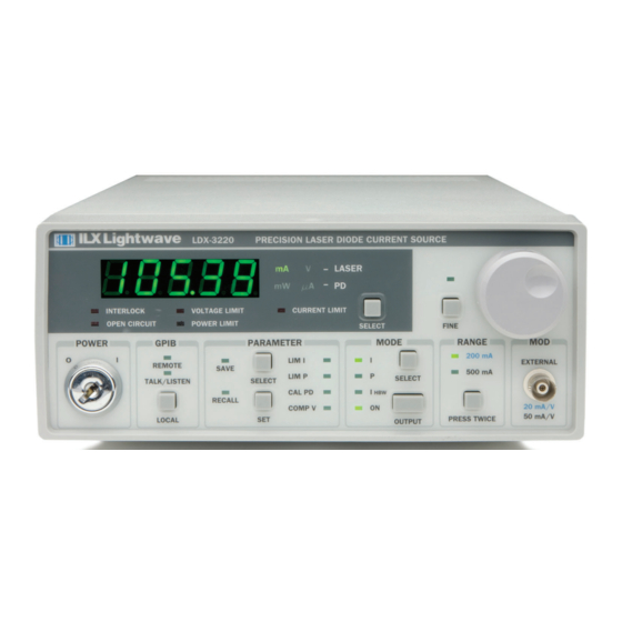
Use these figures to familiarize yourself with the LDX-3200. After that, use Chapter 2 for fundamentals of operating your instrument. Figure 1.1 LDX-3200 Series Front Panel LDX-3200 Series... -
Page 21: Figure 1.2 Ldx-3200 Series Rear Panel
I N T R O D U C T I O N A N D S P E C I F I C A T I O N S C H A P T E R Installing the LDX-3200 Precision Current Source Figure 1.2 LDX-3200 Series Rear Panel 03_21 LDX-3200 Series... -
Page 22: Ldx-3200 Series Specifications
I N T R O D U C T I O N A N D S P E C I F I C A T I O N S C H A P T E R LDX-3200 Series Specifications LDX-3200 Series Specifications Table 1.1 LDX−3200 Series Specifications... - Page 23 I N T R O D U C T I O N A N D S P E C I F I C A T I O N S C H A P T E R LDX-3200 Series Specifications Table 1.1 LDX−3200 Series Specifications...
-
Page 24: Options And Accessories
I N T R O D U C T I O N A N D S P E C I F I C A T I O N S C H A P T E R Options and Accessories Options and Accessories Options and accessories available for the LDX-3200 Series Precision Current Sources include the following: Table 1.2 LDX−3200 Series Accessories Model Number... -
Page 25: Chapter 2 Operation
C H A P T E R PERATION This chapter introduces you to the operation of the LDX-3200 Series Precision Current Source. It offers instructions for connecting your laser to the current source, and describes powering up the instrument. This chapter also contains step by step procedures that teach you how to operate your current source in Constant Current Mode and Constant Power Mode. -
Page 26: The Power-On State
LASER STEP value = 1 (see LAS:STEP command, chapter 4) LASER Tolerance values = 1.00 mA, 1.0 s LASER I setpoint = 0 mA LASER I setpoint = 0 µA LASER P setpoint = 0 mW RECALL bin 0 MODULATION – enabled LDX-3200 Series... -
Page 27: Connecting The Laser
When disconnecting devices, it is only necessary to turn the current source output off. It is also recommended that the connections to the LDX-3200 Series Precision Current Source output be made using twisted wire pairs with an earth-grounded shield (see Figures 2.1 - 2.4). -
Page 28: Figure 2.1 Common Laser Cathode - Photodiode Cathode
Connecting the Laser Figures 2.1 through 2.4 show the possible configurations of connecting laser diodes and photodiodes with the LDX-3200 Series Precision Current Source. Figure 2.1 Common Laser Cathode - Photodiode Cathode Figure 2.2 Common Laser Cathode - Photodiode Anode Figure 2.3 Common Laser Anode - Photodiode Cathode... -
Page 29: Interlock Connections
Usually, this photodiode is internally connected to either the laser anode or cathode. The photodiode and laser connections to the LDX-3200 Series Precision Current Source are electrically isolated from ground and each other. So, if a 4-pin connection is made, (no common connections) no additional jumpers are required. -
Page 30: Setting The Pd Bias
Adjust fully counterclockwise. Grounding Considerations The laser outputs of the LDX-3200 Series Precision Current Source are isolated from chassis ground allowing either output terminal to be grounded at the user's option. Figures 2.1 - 2.4 show the proper earth-ground shielding for laser diode/photodiode connections. -
Page 31: Setting Up The Precision Current Source
When the SELECT switch is released the previous measurement mode will be restored. At this point the LDX-3200 Series current source is in Constant Current Mode, (I), in the 200 mA range, and the display is reading in mA. Next, we need to adjust the set point of the laser current source. - Page 32 An additional feature of the LDX-3200 Series instruments is an adjustable voltage limit. This allows an extra level of laser protection in the event of an intermittent open circuit.
-
Page 33: Operating In Constant Power (P) Mode
LDX-3200 Series instrument allows you to operate the laser current source driver in a Constant Power mode. In this mode, the LDX-3200 Series instrument drives current to the laser to reach a set point power value (in mW). The control loop feedback parameter is photodiode current that the LDX-3200 converts to optical power via a user-defined photodiode responsivity number. - Page 34 C H A P T E R Front Panel Operation The LDX-3200 Series Precision Current Source can be put into a special mode with the CAL PD parameter set to zero. When the CAL PD value is zero, the LASER output will be controlled to the I set point value.
-
Page 35: Error Indicators
C H A P T E R Error Indicators Error Indicators The LDX-3200 Series Precision Current Sources indicate general operational error conditions. Each error condition results in an action as shown in Table 2.2. Table 2.2 LDX−3200 Series Error Indicators... - Page 36 O P E R A T I O N C H A P T E R Error Indicators LDX-3200 Series...
-
Page 37: Remote Operation
(INC) and decrement (DEC) the current set point by a pre-defined step value. The following sections show you the fundamentals of operating your LDX-3200 Series Precision Current Source remotely through the GPIB interface. Reading the GPIB Address Before you can operate the LDX-3200 instrument remotely, you need to know its GPIB address. -
Page 38: Changing Operation From Local To Remote
GPIB bus. LDX-3200 Series Current Source Command Set For the most efficient and effective remote control of your LDX-3200 Series Precision Current Source, we recommend you study the following sections. You will learn about the LDX-3200 command sets, both IEEE488.2 Common Commands and the most used device specific commands, and command syntax. -
Page 39: Table 3.1 Substitute Parameter Names
Series Precision Current Source: LAS:display:ldi Laser:limit:ldi 400 LAS:DIS 1; las:set:ldi?; Las:MODE:Mdp; LAS:OUT 1 The following are examples of invalid syntax for the LDX-3200 Series Precision Current Source. These command strings would produce an erroneous result, as explained: Missing colon, MODE? expected. LAS:MODE MDP Missing semicolon, DEC command generates error. - Page 40 A query has no space between the mnemonic and the question mark, as in: LAS:LDI? The LDX-3200 Series Precision Current Source uses a terminator of <NL><^END> (new line with EOI). For users whose GPIB driver defaults expect a carriage return in the terminator, <CR><NL><^END>, the TERM command may be used for convenience (see TERM command, Chapter 4).
-
Page 41: Command Paths
LDX-3200 Series Current Source Command Set Command Paths The LDX-3200 Series Precision Current Source device-dependent commands are structured into a tree format. Each of the legal paths is listed below, followed by its list of path options, each of which is followed by the commands themselves. It is recommended that the first-time user begin learning the commands by using the full path notation. -
Page 42: Ieee-488.2 Common Commands
DELAY, or *OPC? commands. If the time for a response after one of these commands exceed the GPIB time-out period, a bus (timeout) error will occur. Usually, after this timeout error, the LDX-3200 Series instrument will generate a query error (E302). This error code is reported via the ERR? Query. -
Page 43: Ldx-3200 Commonly Used Commands
LDX-3200 Commonly Used Commands LDX-3200 Commonly Used Commands The LDX-3200 Series Precision Current Source's complete command set contains over 60 commands that allow you to operate the Current Source for a variety of applications. Within the command set, however, is a smaller subset of commands that will meet most of your needs. -
Page 44: Status Reporting
Querying a Condition Register does not change its contents. Figure 3.3 shows the status reporting scheme of the LDX-3200 Series Precision Current Source. Each of the registers which may be accessed by a command or query has the appropriate command or query written above or below the register representation. -
Page 45: Figure 3.3 Ldx-3200 Status Reporting Scheme
This allows the use of the operation complete features of the LDX-3200 Series Precision Current Source, without the need for program looping or polling which can tie up the GPIB. Operation Complete on the LDX-3200 Series Precision Current Source is defined as: No operations to the laser current source hardware are pending. -
Page 46: Output Off Register
The Output Off Register allows you to determine which conditions and events in the LDX-3200 Series Precision Current Source can cause the current source output to be turned off. This register is configured in a manner which is similar to the status reporting registers. -
Page 47: Figure 3.4 Ldx-3200 Output Off Register
R E M O T E O P E R A T I O N C H A P T E R Status Reporting Figure 3.4 LDX-3200 Output Off Register 03_21 LDX-3200 Series ... -
Page 48: Command Timing And Completion
The conditions for setting the operation complete flag are given in the Chapter 3 section titled Operation Complete Definition. All LDX-3200 Series’ device-dependent commands are executed in an overlapped manner, except the DELAY command which is sequential. The operation complete flag is set after the conditions outlined in the Operation Complete Definition have been satisfied. -
Page 49: Table 3.5 Error Code Classifications
<PROGRAM DATA> will not convet to a character value. E-213 <PROGRAM DATA> is incorrect block data length. E-214 <PROGRAM DATA> length exceeds maximum. E-302 Query error. Device was addressed to talk, but GPIB controller failed to read all of the <RESPONSE MESSAGE>. 03_21 LDX-3200 Series ... - Page 50 Laser output must be off to change ranges. E-516 Incorrect Configuration for Calibration Sequence to start. E-519 Setting a measurement is only valid during the calibratin phase for that measurement. User has tried to calibrate a measurement without first entering the requested calibration mode. LDX-3200 Series...
-
Page 51: Command Refeence
This chapter is a guide to all of the device-dependent commands for the LDX-3200 Series Precision Current Source. This chapter is divided into two parts. The first part contains a summary of the remote commands used by the LDX-3200 Series Precision Current Source. - Page 52 C O M M A N D R E F E E N C E C H A P T E R LDX-3200 Series Command Summary Table 4.1 LDX−3200 Series Remote Commands (Continued) (Sheet 2 of 4) Command Parameters Function...
- Page 53 C O M M A N D R E F E E N C E C H A P T E R LDX-3200 Series Command Summary Table 4.1 LDX−3200 Series Remote Commands (Continued) (Sheet 3 of 4) Command Parameters Function Sets laser current limit setpoint (LDX-3210 high range).
- Page 54 C O M M A N D R E F E E N C E C H A P T E R LDX-3200 Series Command Summary Table 4.1 LDX−3200 Series Remote Commands (Continued) (Sheet 4 of 4) Command Parameters Function Sets the output current tolerance value and time window.
-
Page 55: Ldx-3200 Series Device-Dependent Commands
C O M M A N D R E F E E N C E C H A P T E R LDX-3200 Series Device-Dependent Commands LDX-3200 Series Device-Dependent Commands This section contains all of the device-dependent commands for the LDX-3200 Series Precision Current Source, listed in alphabetical order. -
Page 56: Ldx-3200 Series Command Reference
The following pages contain a reference for the device-dependent commands of the LDX-3200 Series Precision Current Source. This reference contains useful information for both local and remote operation of the LDX-3200 Series Precision Current Source. References to the front panel labels are capitalized in the following reference pages (as is done throughout this manual). - Page 57 C O M M A N D R E F E E N C E C H A P T E R LDX-3200 Series Command Reference ERRors? RONT ANEL EMOTE The ERRors? query returns a list of command and device errors that have occurred since the last query.
- Page 58 C O M M A N D R E F E E N C E C H A P T E R LDX-3200 Series Command Reference LASer:CALMD? RONT ANEL EMOTE The LASer:CALMD? query returns the value of the laser's photodiode feedback responsivity (CAL PD parameter) setting.
- Page 59 C O M M A N D R E F E E N C E C H A P T E R LDX-3200 Series Command Reference LASer:CAL:LDI RONT ANEL EMOTE The LASer:CAL:LDI command is used to enter the LASER current setpoint, measurement, and limit (in low bandwidth mode) calibration mode.
- Page 60 C O M M A N D R E F E E N C E C H A P T E R LDX-3200 Series Command Reference LASer:CAL:LDI? RONT ANEL EMOTE The LASer:CAL:LDI? query is used to determine that the LDX-3200 is ready for a value to be entered during the calibration cycle of the LASer:CAL:LDI mode.
- Page 61 C O M M A N D R E F E E N C E C H A P T E R LDX-3200 Series Command Reference LASer:CAL:LDV? RONT ANEL EMOTE The LASer:CAL:LDV? query is used to determine that the LDX-3200 is ready for a value to be entered during the calibration cycle of the LASer:CAL:LDV mode.
- Page 62 C O M M A N D R E F E E N C E C H A P T E R LDX-3200 Series Command Reference LASer:CAL:MDI RONT ANEL EMOTE The LASer:CAL:MDI command is used to enter the LASER photodiode current calibration mode.
- Page 63 C O M M A N D R E F E E N C E C H A P T E R LDX-3200 Series Command Reference LASer:COND? RONT ANEL EMOTE The LASer:COND? query returns the value of the status condition register of the LASER operations.
- Page 64 C O M M A N D R E F E E N C E C H A P T E R LDX-3200 Series Command Reference LASer:DEC RONT ANEL EMOTE The LASer:DEC command decrements the selected laser control mode setpoint by one or more steps.
- Page 65 C O M M A N D R E F E E N C E C H A P T E R LDX-3200 Series Command Reference LASer:DISplay RONT ANEL EMOTE The LASer:DISplay command enables or disables (turns off) the display and some LEDs Syntax Diagram <white...
- Page 66 C O M M A N D R E F E E N C E C H A P T E R LDX-3200 Series Command Reference LASer:DISplay:LDI RONT ANEL EMOTE The LASer:DISplay:LDI command sets the laser display to show the constant current measurement.
- Page 67 C O M M A N D R E F E E N C E C H A P T E R LDX-3200 Series Command Reference LASer:DISplay:LDV RONT ANEL EMOTE The LASer:DISplay:LDV command sets the laser display to show the laser forward voltage measurement.
- Page 68 C O M M A N D R E F E E N C E C H A P T E R LDX-3200 Series Command Reference LASer:DISplay:MDI RONT ANEL EMOTE The LASer:DISplay:MDI command sets the laser display to show the monitor photodiode current measurement.
- Page 69 C O M M A N D R E F E E N C E C H A P T E R LDX-3200 Series Command Reference LASer:DISplay:MDP RONT ANEL EMOTE The LASer:DISplay:MDP command sets the display to show the monitor photodiode power measurement.
- Page 70 C O M M A N D R E F E E N C E C H A P T E R LDX-3200 Series Command Reference LASer:DISplay:PARAM RONT ANEL EMOTE The LASer:DISplay:PARAM command enables the display to show the parameter values.
- Page 71 C O M M A N D R E F E E N C E C H A P T E R LDX-3200 Series Command Reference LASer:DISplay:SET? RONT ANEL EMOTE The LASer:DISplay:SET? query returns the status of the setpoint display mode.
- Page 72 C O M M A N D R E F E E N C E C H A P T E R LDX-3200 Series Command Reference LASer:ENABle:COND RONT ANEL EMOTE The LASer:ENABle:COND command sets the condition status enable register of the LASER operations for summary (in bit 3 of the status byte) and generation of service requests.
- Page 73 C O M M A N D R E F E E N C E C H A P T E R LDX-3200 Series Command Reference LASer:ENABle:COND? RONT ANEL EMOTE The LASer:ENABle:COND? query returns the value of the status condition enable register of the LASER operations.
- Page 74 C O M M A N D R E F E E N C E C H A P T E R LDX-3200 Series Command Reference LASer:ENABle:EVEnt RONT ANEL EMOTE The LASer:ENABle:EVEnt command sets the status event enable register of the LASER operations.
- Page 75 C O M M A N D R E F E E N C E C H A P T E R LDX-3200 Series Command Reference LASer:ENABle:EVEnt? RONT ANEL EMOTE The LASer:ENABle:EVEnt? query returns the value of the status event enable register of the LASER operations.
- Page 76 C O M M A N D R E F E E N C E C H A P T E R LDX-3200 Series Command Reference LASer:ENABle:OUTOFF RONT ANEL EMOTE The LASer:ENABle:OUTOFF command sets the status outoff enable register of the LASER operations (things that will turn the LASER output off).
- Page 77 C O M M A N D R E F E E N C E C H A P T E R LDX-3200 Series Command Reference LASer:ENABle:OUTOFF? RONT ANEL EMOTE The LASer:ENABle:OUTOFF? query returns the value of the status outoff enable register of the LASER operations.
- Page 78 C O M M A N D R E F E E N C E C H A P T E R LDX-3200 Series Command Reference LASer:EVEnt? RONT ANEL EMOTE The LASer:EVEnt? query returns the value of the status event register of the LASER operations.
- Page 79 C O M M A N D R E F E E N C E C H A P T E R LDX-3200 Series Command Reference LASer:INC RONT ANEL EMOTE The LASer:INC command increments the selected laser control mode setpoint by one or more steps.
- Page 80 C O M M A N D R E F E E N C E C H A P T E R LDX-3200 Series Command Reference LASer:LDI RONT ANEL EMOTE The LASer:LDI command sets the laser control current. Syntax Diagram <white...
- Page 81 C O M M A N D R E F E E N C E C H A P T E R LDX-3200 Series Command Reference LASer:LDV RONT ANEL EMOTE The LASer:LDV command sets the laser voltage for calibration of the laser voltage measurement.
- Page 82 C O M M A N D R E F E E N C E C H A P T E R LDX-3200 Series Command Reference LASer:LIMit:I1 RONT ANEL EMOTE The LASer:LIMit:I1 command sets the LASER current limit value for the 100 mA range on the LDX-3210.
- Page 83 C O M M A N D R E F E E N C E C H A P T E R LDX-3200 Series Command Reference LASer:LIMit:I2 RONT ANEL EMOTE The LASer:LIMit:I2 command sets the LASER current limit value for the 200 mA range on the LDX-3220.
- Page 84 C O M M A N D R E F E E N C E C H A P T E R LDX-3200 Series Command Reference LASer:LIMit:I5 RONT ANEL EMOTE The LASer:LIMit:I5 command sets the LASER current limit value for the 50 mA range on the LDX-3210 and the 500 mA range on the LDX-3220.
- Page 85 C O M M A N D R E F E E N C E C H A P T E R LDX-3200 Series Command Reference LASer:LIMit:MDP RONT ANEL EMOTE The LASer:LIMit:MDP command sets the laser monitor photodiode power limit value.
- Page 86 C O M M A N D R E F E E N C E C H A P T E R LDX-3200 Series Command Reference LASer:LIMit:V RONT ANEL EMOTE The LASer:LIMit:V command sets the LASER compliance voltage limit value.
- Page 87 C O M M A N D R E F E E N C E C H A P T E R LDX-3200 Series Command Reference LASer:MDI RONT ANEL EMOTE The LASer:MDI command sets the value of the optical power setpoint, in µA, if the CALMD (CAL PD) responsivity is 0.
- Page 88 C O M M A N D R E F E E N C E C H A P T E R LDX-3200 Series Command Reference LASer:MDLN (LDX-3220 only) RONT ANEL EMOTE The LASer:MDLN command enables or disables (turns off) the front panel modulation input (BNC).
- Page 89 C O M M A N D R E F E E N C E C H A P T E R LDX-3200 Series Command Reference LASer:MDP RONT ANEL EMOTE The LASer:MDP command sets the value of the optical power setpoint in mW if the CALMD (CAL PD) responsivity is greater than 0.
- Page 90 C O M M A N D R E F E E N C E C H A P T E R LDX-3200 Series Command Reference LASer:MODE? RONT ANEL EMOTE The LASer:MODE? query returns the selected laser control mode. MODE...
- Page 91 C O M M A N D R E F E E N C E C H A P T E R LDX-3200 Series Command Reference LASer:MODE:ILBW RONT ANEL EMOTE The LASer:MODE:ILBW command selects laser constant current mode. MODE ILBW...
- Page 92 C O M M A N D R E F E E N C E C H A P T E R LDX-3200 Series Command Reference LASer:OUTput RONT ANEL EMOTE The LASer:OUTput command turns the laser output on or off.
- Page 93 C O M M A N D R E F E E N C E C H A P T E R LDX-3200 Series Command Reference LASer:RANge RONT ANEL EMOTE The LASer:RANge command selects the laser's drive current output range.
- Page 94 C O M M A N D R E F E E N C E C H A P T E R LDX-3200 Series Command Reference LASer:SET:LDI? RONT ANEL EMOTE The LASer:SET:LDI? query returns the constant I value that is used for both output ranges and both bandwidths.
- Page 95 C O M M A N D R E F E E N C E C H A P T E R LDX-3200 Series Command Reference LASer:SET:MDI? RONT ANEL EMOTE The LASer:SET:MDI? query returns the laser monitor photodiode current setpoint value (when CALPD=0), in µA.
- Page 96 C O M M A N D R E F E E N C E C H A P T E R LDX-3200 Series Command Reference LASer:SET:MDP? RONT ANEL EMOTE The LASer:SET:MDP? query returns the laser monitor photodiode power setpoint value (when CALMD [CAL PD] is not zero), in mW.
- Page 97 C O M M A N D R E F E E N C E C H A P T E R LDX-3200 Series Command Reference LASer:STEP? RONT ANEL EMOTE The LASer:STEP? query is used to read back the LASer STEP value. This value is used to increment or decrement the selected laser control mode setpoint by the given amount when used with the LASer:INC or LASer:DEC command.
- Page 98 C O M M A N D R E F E E N C E C H A P T E R LDX-3200 Series Command Reference LASer:TOLerance? RONT ANEL EMOTE The LASer:TOLerance? query allows the programmer to determine how the LASER current tolerance is set.
- Page 99 C O M M A N D R E F E E N C E C H A P T E R LDX-3200 Series Command Reference MESsage? RONT ANEL EMOTE The MESsage? query returns the previously stored message. This message will always be 16 bytes long and enclosed in quotes.
- Page 100 C O M M A N D R E F E E N C E C H A P T E R LDX-3200 Series Command Reference RADix RONT ANEL EMOTE The RADix command allows the programmer to select the radix type for status, condition, and event query response data.
- Page 101 C O M M A N D R E F E E N C E C H A P T E R LDX-3200 Series Command Reference RADix? RONT ANEL EMOTE The RADix? query allows the programmer to determine that radix type for status, condition, and event query response data is currently selected.
- Page 102 C O M M A N D R E F E E N C E C H A P T E R LDX-3200 Series Command Reference TERM RONT ANEL EMOTE The TERM command allows the programmer to change the default (GPIB/IEEE488 standard) terminator to include the carriage return.
- Page 103 C O M M A N D R E F E E N C E C H A P T E R LDX-3200 Series Command Reference TIME? RONT ANEL EMOTE The TIME? query allows the programmer to determine how much time has passed since the LDX-3200 was last powered up.
- Page 104 C O M M A N D R E F E E N C E C H A P T E R LDX-3200 Series Command Reference LDX-3200 Series...
-
Page 105: Saving And Recalling From The Front Panel
& F UNCTIONS EATURES This chapter introduces you to the LDX-3200 Series Precision Current Source functions and operating features such as event triggering, analog modulation of laser current, and Save and Recall. Saving and Recalling from the Front Panel... -
Page 106: Saving And Recalling Under Remote Operation
The closer the laser voltage limit shut off point is to the operating voltage of your laser, the faster the circuit will work in the event of an open circuit. Some experimentation may be necessary for optimum results. LDX-3200 Series... -
Page 107: Using The Ldx-3200 Current Source's Trigger Function
20 ms minimum. A one shot trigger pulse will occur on power up of the instrument due to the states of the processor I/O. Figure 5.1 LDX-3200 Series Rear Panel 03_21 LDX-3200 Series ... -
Page 108: Modulating The Laser Current Source
200 mA range, high bandwidth mode with a limit of 175 mA. The allowable bandwidth of the modulated analog signal, defined as the 3 dB roll off point, is dependent on the LDX-3200 Series family member, the output current range, and the mode (constant current low/high bandwidth). See the section, Laser Current Source Specifications, in Chapter 1 for external analog modulation bandwidth specifications. - Page 109 LED in our example experiment. Thus, it is safe to disconnect the test device (LED) when the LDX-3200’s output is off, regardless of the presence of the modulation signal. 03_21 LDX-3200 Series ...
- Page 110 F U N C T I O N S & F E A T U R E S C H A P T E R Modulating the Laser Current Source LDX-3200 Series...
-
Page 111: Calibration Overview
The current limits are calibrated internally by the instrument as part of the calibration process. Your LDX-3200 Series Current Source can be calibrated with the case closed. It should be calibrated every 12 months or whenever performance verification indicates that calibration is necessary, such as differences between set point and measurement display values which exceed the accuracy specification. -
Page 112: Recommended Equipment
C A L I B R A T I O N & T R O U B L E S H O O T I N G C H A P T E R Recommended Equipment Finally, the LDX-3200 Series Current Source should be allowed to warm up for at least 1 hour before calibration. Recommended Equipment Recommended test equipment for calibrating the LDX-3200 Series Current Source is listed in Table 6.1. -
Page 113: Figure 6.1 Ipd Calibration Circuit
100 , 1/4 W resistor, 1% 1.0 M, 1/4 W resistor, 1% 49 , 1/2 W resistor, low TCR LDX-3210 11 , 1 W resistor, low TCR LDX-3220 TIL 117 opto-isolator Figure 6.1 I Calibration Circuit 03_21 LDX-3200 Series ... -
Page 114: Local Calibration Of The Ldx-3200 Series Current Source
Local Calibration of the LDX-3200 Series Current Source There are three calibration adjustments required for the LASER current source of the LDX-3200 Series Current Source. They are calibration of the constant current source for both bandwidths and ranges, calibration of the laser voltage measurement, and calibration of the constant light power (I ) feedback circuits. -
Page 115: Ipd Current Calibration
(PARAMETER) SET switch is released, the Current Source will calculate the calibration constants and store them to nonvolatile memory. In low bandwidth calibration mode, the LDX-3200 Series Current Source will also perform current limit calibration, indicated by the CURRENT LIMIT LED flashing. - Page 116 After a few seconds the display will show the I set point value. After the value on the display is stable (has not changed by more than one digit for several seconds) the LDX-3200 Series Current Source is ready for the actual I value to be entered.
-
Page 117: Laser Forward Voltage (Ldv) Measurement Calibration
Once the second actual voltage value is entered, the Current Source will store the new calibration constants. This ends the section on front panel calibration of your LDX-3200 Series Current Source. The next section discusses calibration through the IEEE488.2 GPIB interface. -
Page 118: Remote Calibration Of The Ldx-3200 Series Current Source
Remote Calibration of the LDX-3200 Series Current Source Remote Calibration of the LDX-3200 Series Current Source The LDX-3200 Series Current Sources can be calibrated remotely via the GPIB Interface. All of the required calibration commands are listed in Table 4.1 in Chapter 4. - Page 119 Once the second actual I value is entered via the LAS:LDI command, the new calibration constants will be calculated and stored into non-volatile memory. In low bandwidth calibration mode, the LDX-3200 Series Current Source will also perform current limit calibration as indicated by the CURRENT LIMIT LED flashing. The *OPC? query may be used (after the LAS:LDI value is sent) to determine when the calibration is completed.
-
Page 120: Remote Ipd Current Calibration
P modes. When these values are reached and are stable, the user enters the actual value of the current, as measured by an external DMM. The LDX-3200 Series Current Source then automatically calibrates the laser feedback circuits. Configure the Current Source in the following manner for the Laser Current Source calibration: Table 6.7 Remote I... -
Page 121: Remote Calibration Of Laser Forward Voltage (Ldv) Measurement
Enter the measured voltage (in volts) via the LAS:LDV <nrf value> command. The measured value of the voltage should not be entered until the LDX-3200 Series Current Source is ready to receive it. The current source will be ready to receive the voltage value when, after a LAS:CAL:LDV? query is sent, the response from the Current Source is "1". -
Page 122: Troubleshooting Guide
Troubleshooting Guide Troubleshooting Guide This section is a guide to troubleshooting the LDX-3200 Series Current Sources. Some of the more common symptoms are listed here, and the appropriate troubleshooting actions are given. We recommend that the user start at the beginning of this guide. - Page 123 A high impdeance may cause this problem. Open Circuit Error E503 or The LDX-3200 Series of instuments have an adjustable laser compliance voltage. Check to see that the laser Voltage Limit Error E505 voltage limit setting is not too low. Check laser connections.
- Page 124 C A L I B R A T I O N & T R O U B L E S H O O T I N G C H A P T E R Troubleshooting Guide LDX-3200 Series...
Need help?
Do you have a question about the LDX-3200 Series and is the answer not in the manual?
Questions and answers