
Related Manuals for Newport LDP-3811

Summary of Contents for Newport LDP-3811
- Page 1 User’s Guide Laser Diode Precision Pulsed Supply LDP-3811 70002406 August 2019 70002406 A t 2019...
-
Page 3: Table Of Contents
Power-Up Sequence ..........6 Introduction to the LDP-3811 Front Panel ......8 Front Panel Familiarization . - Page 4 Common Commands ..........29 3811 Device-Dependent Commands ....... . 30 LDP-3811...
- Page 5 Error Messages ..........73 LDP-3811 Programming Examples ....... . . 73 Chapter 4 GPIB/IEEE-488.2 Remote Operation...
- Page 6 3811 Remote Messages ........104 Non-Supported Remote Interface Messages ..... . . 104 LDP-3811...
- Page 7 More Information ......... . . 119 08_19 LDP-3811...
- Page 8 T A B L E O F C O N T E N T S LDP-3811...
- Page 9 Table 2.1 LDP-3811 Default Settings......7 Table 2.2 Error Indicators........17 Table 3.1 Substitute Parameter Names .
- Page 10 L I S T O F T A B L E S viii LDP-3811...
- Page 11 Figure 2.1 LDP-3811 Front Panel ........8...
- Page 12 Figure 4.11 <PROGRAM DATA SEPARATOR> Syntax Diagram ..99 Figure 4.12 LDP-3811 Status Reporting Schematic Diagram ..101 Figure 4.13 3811 Output Off Register ......104 Figure 5.1 Power Line Voltage Selection .
-
Page 13: Safety Information And The Manual
(see the contact information on page xiv). All instruments returned to ILX Lightwave are required to have a Return Authorization Number assigned by an official representative of ILX Lightwave Corporation. See Returning an Instrument on page xiii for more information. LDP-3811 ... -
Page 14: Safety Marking Symbols
Terminal Terminal On: In position of a bistable push control. Off: Out position of a bistable push control. The slash (I) only denotes that mains are on. The circle (O) only denotes that mains are off. LDP-3811... - Page 15 3 inches (7.5 cm) of compressible packaging material on all sides. Repairs are made and the instrument returned transportation pre-paid. Repairs are warranted for the remainder of the original warranty or for 90 days, whichever is greater. xiii 08_19 LDP-3811 ...
-
Page 16: Comments, Suggestions, And Problems
Fax ..........(406) 586-9405 Online: ......www.newport.com/b/ilx-lightwave Email: . - Page 17 If the original shipping container is not available, place your instrument in a container with at least 3 inches (7.5 cm) of compressible packaging material on all sides. We look forward to serving you even better in the future! 08_19 LDP-3811 ...
- Page 18 W A R R A N T Y LDP-3811...
-
Page 19: Introduction And Specifications
Laser Diode Precision Pulsed Supply and optional Model 1231 GPIB/IEEE-488.2 Interface. If you want to get started right away, read Appendix B (Quick Start) first. Chapter 2 has a section for quick familiarization of the LDP-3811 front panel and also provides an in-depth operation reference. -
Page 20: Specifications
Accuracy 10 ns +0.01% of reading Pulse Rise / Fall Time < 25 ns Pulse Repetion Interval (PRI) 1 to > 1000 s Range Resolution 100 ns Accuracy 10 ns +0.01% of reading Duty Cycle 0.01% to 100% LDP-3811... - Page 21 3. Measured after a 2 usec settling time. 4. Over any 10 minute interval, half scale output. 5. Over a 24 hour period, half scale output. 6. Measured from 10% to 90% points at half scale output. 08_19 LDP-3811 ...
- Page 22 Our goal is to make the best laser diode instrumentation available anywhere. To achieve this, we need your ideas and comments on ways we can improve out products. We invite you to contact us at any time with your suggestions. LDP-3811...
-
Page 23: Installation And Configuration
Installation AC Power Considerations The LDP-3811 can be configured to operate at nominal line voltages of 100/120 / 220-230/240 VAC. This is set internally at the factory and should not be changed. However, check to be sure that the voltage printed on the back panel of the instrument matches the power-line voltage in your area. -
Page 24: Tilt-Foot Adjustment
Power-Up Sequence Tilt-Foot Adjustment The LDP-3811 has front legs that extend to make it easier to view the LED displays. To use them, place the LDP-3811 on a stable base and rotate the legs downward until they lock into position. -
Page 25: Table 2.1 Ldp-3811 Default Settings
Pulse Repetition Interval (PRI) = 1.0 uSec Duty Cycle % - 10.0% Display showing current (in mA) RANGE in 200 mA setting Set Point = 0 mA RECALL BIN number = 0 STEP value = 0.01 mA Table 2.1 LDP-3811 Default Settings 08_19 LDP-3811 ... -
Page 26: Introduction To The Ldp-3811 Front Panel
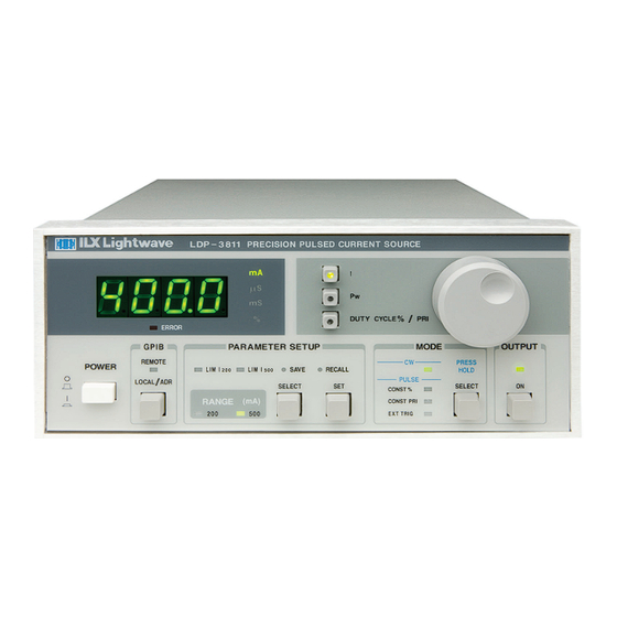
Note: Later in this chapter, there is a quick introduction to the front panel functions by briefly describing the switches and indicators. Figure 2.1 LDP-3811 Front Panel Front Panel Familiarization Refer to Figure 2.1 for the following discussions of the LDP-3811 front panel sections. The key words are in bold for easy identification. LDP-3811... -
Page 27: General Functions
The POWER switch is used to power-up and power-down the LDP-3811. The ADJUST knob, used for entering values, is the large knob on the LDP-3811 front panel. To the left of the ADJUST knob are the display switches, I, PW, and DUTY CYCLE% / PRI. -
Page 28: Gpib Section
Local Lockout. ADJUST Section The ADJUST section is located on the right side of the LDP-3811 front panel. It consists of the ADJUST (control) knob. The ADJUST knob is used to change the set points, enter parameter values, enter the GPIB address, or enter instrument calibration data. -
Page 29: Mode Select
(MODE) SELECT switch is pressed, the OUTPUT is forced off. MODE Indicators The CW indicator becomes lit when the LDP-3811 is in the Continuous Wave (DC) mode. When CW mode is selected, the laser drive current output is controlled to the laser drive current (I) set point value. -
Page 30: Constant Pulse Repetition Interval (Const Pri) Mode
11.00%, and PW was then set to 0.1 uSec, CDC would be forced to 10.00% because PRI cannot be less than 1.0 uSec. Likewise, if the Duty Cycle % is changed, the LDP-3811 will automatically allow only valid Duty Cycle % values (based on the present PW value) to be selected. -
Page 31: Display Switch Section
Pressing the PW switch causes the output pulse width to be displayed, if the LDP-3811 is in CONST %, CONST PRI, or EXT TRIG mode. If the LDP-3811 is in CW mode, the PW switch is disabled. The PW indicator becomes lit when pulse width is displayed. -
Page 32: Parameter Setup Select Switch
The SET switch is used to enter SET mode, where parameter values are stored into non-volatile memory. If the SET switch is pressed while the LDP-3811 is in SELECT mode, the LDP- 3811 will enter SET mode. While the SET switch is held in, the selected parameter value can be changed by turning the ADJUST knob. -
Page 33: Save And Recall Parameter Functions
LDP-3811 are stored. The user selects a "bin" number (1 - 10) for saving the parameters. Then, when that "bin" number is recalled, the LDP-3811 parameters are reconfigured to the previously stored values. - Page 34 When the SET switch is released, the range which was last selected on the display will be enabled, and the present setup will be stored in non-volatile memory. During LDP-3811 operation, the enabled laser drive current output RANGE indicator is always lit. ...
-
Page 35: Error Indicators
Introduction to the LDP-3811 Front Panel Error Indicators The LDP-3811 error indicators are shown in Figure 2.5. The functions of the most common LDP-3811 errors are shown in Table 2.2. The entire error code listing for the LDP-3811 is given in Appendix A. -
Page 36: Back Panel Controls And Connections
Figure 2.7 Back Panel 9-Pin OUTPUT Connector Connecting to Your Laser When connecting laser diodes and other sensitive devices to the LDP-3811, we recommend that the unit be powered-up and the OUTPUT be off. In this condition, a low impedance shunt is active across the output terminals. When disconnecting devices, it is only necessary to turn the OUTPUT off. -
Page 37: Laser Diode Connections And Shielding
OUTPUT connectors on the back panel. The OUT trigger signal has the same pulse width and repetition interval as the OUTPUT signal, but at TTL level. This signal is available whenever the LDP-3811 is in one of the three Pulse modes of operation. -
Page 38: Gpib Connector
C H A P T E R Back Panel Controls and Connections The IN trigger signal can be used to fire an OUTPUT pulse from the LDP-3811 when it is in EXT TRIG mode. The trigger signal should be at TTL level, and the LDP-3811 will be triggered on a rising edge (transition from low to high). -
Page 39: General Operating Procedures
Remote operations are discussed in Chapter 4. Warm-up and Environmental Considerations Operate the LDP-3811 at an ambient temperature in the range of 0 to +50 Storage temperatures should be in the range of -40 to +70 C. To achieve rated accuracy, let the LDP-3811 warm up for at least 1 hour before use. - Page 40 If the MODE of operation is changed, the OUTPUT will be forced off. When the LDP-3811 is powered off, the state of the unit at power-down is saved in non-volatile memory. For operation in Constant Pulse Repetition Interval (CONST PRI) mode, follow the above procedure, with the following changes.
-
Page 41: Cw Mode Operation
ADJUST knob again until the desired value is displayed. Select the CW mode. If the LDP-3811 is presently in a PULSE mode, press and hold in the (MODE) SELECT switch until the present mode LED indicator begins to flash. -
Page 42: Trigger Out Operation
General Operating Procedures TRIGGER OUT Operation The OUT trigger signal is available whenever the LDP-3811 is operated in a PULSE mode. The OUT trigger signal has the same pulse width as the OUTPUT signal, but at TTL level. To use the OUT trigger, connect the device which is to be triggered (from the LDP-3811) to the LDP-3811's back panel OUT (BNC) connector. - Page 43 <nrf value> refers to the IEEE-488.2 standard for numeric format notation. It is a generic label which means either integer, floating point, scientific notation number representation may be used. For more information on terminology, see Chapter 4. LDP-3811 ...
-
Page 44: Command Reference
Many of the 3811 remote commands require a compound structure. This is done to distinguish between different commands of the same type. The compound command structure is similar to a directory path structure, as found in DOS. For example, commands which deal with the 3811's current limit LDP-3811... -
Page 45: Table 3.2 Ldp-3811 Device-Dependent Commands
For more information, see page 32, presenting a more detailed look at the 3811 device-dependent commands, including syntax diagrams, and example usage. Table 3.2 LDP-3811 Device-Dependent Commands NAME PARAMETERS FUNCTION... - Page 46 Returns the mode, CW (continuous wave), PRI (constant pulse repetition interval), DUTY (constant duty cycle %) or EXT (external trigger) MODE:CDC None Sets the LDP-3811 to CDC (constant duty cycle) mode MODE:CW None Sets the LDP-3811 to CW (continuous wave) mode MODE:EXT...
-
Page 47: Common Commands
Sets the program message terminator TERM? None Returns the program message terminator TIME? None Returns the elapsed time since the LDP-3811 was last powered up TIMER? None Returns the elapsed time since the timer was last reset Common Commands Another type of command is the "common command". These commands are common to instruments which support the ANSI-IEEE-488.2 standard and are not... -
Page 48: 3811 Device-Dependent Commands
See Figure 3.2 for command path tree structure. All of the 3811's common commands and queries are listed in Section 4.3. The lower level remote interface messages are also listed in Chapter 4. Figure 3.1 Command Description Format LDP-3811... -
Page 49: Command Paths
It is recommended that the first-time user begin learning the commands by using the full path notation. Once the user is familiar with the commands, he or she may wish to take advantage of the shortcuts allowed for command paths. Figure 3.2 Command Path Structure 08_19 LDP-3811 ... -
Page 50: 3811 Device-Command Reference
<nrf value> refers to the IEEE-488.2 standard for numeric format notation. It is a generic label which means either integer, floating point, scientific notation number representation may be used. ANSI/IEEE-488.2 defined terms are indicated by the <> brackets. For more information on terminology, see Chapter 4. LDP-3811... - Page 51 The CAL:LDI? query may be used to determine if the 3811 is ready for the user to enter the correct value (in mA) via the LDI command. Examples “CAL:LDI” - action: the 3811 enters calibration mode for laser drive current “CAL:Ldi” - action: the 3811 enters calibration mode for laser drive current 08_19 LDP-3811 ...
- Page 52 “Cal:LDI?” - response: 0, means the 3811 is not yet ready for the user to enter a laser drive current value (because it is busy with internal operations which don’t require user input, or an error has occurred). LDP-3811...
- Page 53 “CDC 40.0” - action: the constant duty cycle set point is set to 40.00% “Cdc20; Set:cdc?” - returns: 20.5, means that although the constant duty cycle set point is initially set to 20.00%, 20.50% is the closest valid duty cycle (based on the present PW value). 08_19 LDP-3811 ...
- Page 54 (based on the present PW and the resolution of the PW and PRI parameters). The actual CDC value is then set to the set point CDC value. Examples “cdc?” - response: 90.6 means the actual duty cycle is 90.60%. LDP-3811...
- Page 55 The condition status may be constantly changing, while the event status is only cleared when the event status is read or the *CLS command is issued. Examples “COND?” - response: 1025, means that the laser drive current limit and output on conditions currently exist. 08_19 LDP-3811 ...
- Page 56 “Ldi 22; Delay 2000; Ldi?” - actions: the laser drive current is set to 22.00 mA, then the 3811 waits for 2.0 seconds before measuring and returning the measured output current. LDP-3811...
- Page 57 “DIS?” - response: “99.9” means the value on the display is 99.9. “DISp?” - response” 00.6” means the value on the display is 0.6. “Disp?” - response: “E501” means there is an E501 error message on the display (which means: interlock open -- output off). 08_19 LDP-3811 ...
- Page 58 “Mode:PRI; Display:Const” - action: sets the 3811 to constant PRI mode and activates the display to show the PRI set point value. “Mode:CDC; Dis:CONST” - action: sets the 3811 to constant duty cycle mode and activates the display to show the duty cycle percentage set point value. LDP-3811...
- Page 59 In local operation, the LDI display is activated by pressing the I switch. Examples “DIS:LDI” - action: activates the I switch and sets the display to show laser drive current. “Disp:Ldi” - action: activates the I switch and sets the display to show the laser drive current. 08_19 LDP-3811 ...
- Page 60 (PW) value. “Mode:CW; Dis:PW” - action: sets the 3811 to continuous wave mode, but the display changes to show LDI (not PW) because the pulse width value is not used in CW mode. LDP-3811...
- Page 61 “Display:PW?” - response: 1, means the PW switch is activated. ENABle: RONT ANEL REMOTE The ENABle: command path is used to get to the 3811’s status enable commands. The following commands may be reached directly from the ENABle: command path: ENABle:COND ENABle:COND? ENABle:EVEnt ENABle:EVEnt? ENABle:OUTOFF ENABle:OUTOFF? 08_19 LDP-3811 ...
- Page 62 Voltage Limit/Open Circuit and Laser Drive Current Limit conditions will be summarized in the status byte (bit 3). “Enable:Cond #H7C33” - action: enables the status conditon register so that any and all of the above conditions will be reported in the status byte register (bit 3). LDP-3811...
- Page 63 Interlock Open conditions will be reported (in summarized form) to the status byte (bit 3). “Radix Hex; Enable:Cond?” - response: #H2001, means that the laser drive current limit and hardware error conditions will be reported (in summarized form) to the status type (bit 3). 08_19 LDP-3811 ...
- Page 64 (in summarized form) to the status byte (bit 2). “Enable:Event #H7C33” - action: enables the status Event register so all of the above events will be reported (in summarized form) to the status byte (bit 2). LDP-3811...
- Page 65 (in summarized form) to the status byte register (bit 2). “Radix Hex; Enab:Eve?” - response: #H7C33, means that all of the above events will be reported (in summarized form) to the status byte register (bit 2). 08_19 LDP-3811 ...
- Page 66 “ENAB:OUTOFF?” - response: 0, means that the laser drive current limit condition will not cause the laser drive current output to be turned off. “ENAB:OUTOFF?” - response: 1, means that the laser drive current limit condition will cause the laser drive current output to be turned off. LDP-3811...
- Page 67 The response data is sent as character data. Examples “ERR?” - response: 0, means no errors reported. “Errors?” - response: 201, means that the <PROGRAM DATA> (command parameter) value out of range error was reported since the last ERRors? query. 08_19 LDP-3811 ...
- Page 68 “EVE?” - response: 1025, means that the output on/off state changed and laser drive current limit events occurred since the last EVE? query. “Radix Hex; Laser:Event?” - response: #H22, means that the KEYLOCK state changed and voltage limit/open circuit event has occurred since the last EVEnt? query. LDP-3811...
- Page 69 (in mA) to calibrate the laser diode current measurement. In remote mode, the resolution is 0.01 mA. Examples “LDI 40” - action: sets the laser drive current to 40.00 mA. “ldi 100.0” - action: sets the laser drive current to 100.00 mA. 08_19 LDP-3811 ...
- Page 70 “ldi?” - response: 30.0, means the measured laser drive current is 30.00 mA. LIMit: RONT ANEL REMOTE The LIMit: command path is used to get to the 3811’s limit commands and queries. The following commands and queries may be reached directly from the LIMit: command path. LIMit:I200 LIMit:I200? LIMit:I500 LIMit:I500? LDP-3811...
- Page 71 The current limit is valid for all modes of laser operation, while in the 200 mA range. Examples “LIM:I200?” - response: 40.0, means the current limit is 40.0 mA. “lim:I200?” - response: 50.0, means the current limit is 50.0 mA. 08_19 LDP-3811 ...
- Page 72 The current limit is valid for all modes of laser operation, while in the 500 mA range. Examples “LIM:I500?” - response: 40.0, means the current limit is 40.0 mA. “lim:I500?” - response: 500.0, means the current limit is 500.0 mA. LDP-3811...
- Page 73 “0000000”, all spaces. Examples “MES?” - response: “Test 30000000”, means the previously stored message was “Test 3”. “Message?” - response: “This is a test.”, means the previously stored message was “This is a test.” 08_19 LDP-3811 ...
- Page 74 (pulsed) mode is in effect for the laser drive current output. MODE: RONT ANEL REMOTE The MODE: command path is used to get to the 3811’s laser mode selection commands. The following commands may be reached directly from the MODE: command path. MODE:CDC MODE:CW MODE:EXT MODE:PRI LDP-3811...
- Page 75 This command has the same effect as selecting CW mode on the 3811 front panel. In this mode, the pulse circuit is turned off. Examples “mode:cw” - action: enables the (CW) continuous wave (for laser drive current) mode. 08_19 LDP-3811 ...
- Page 76 In this mode, the laser drive current pulse repetition interval is constant. However, the PRI value cannot be set less than the PW value. Examples “MODE:PRI” - action: sets the laser drive current output for constant pulse repetition interval (pulsed) mode. LDP-3811...
- Page 77 1, due to the two second OUTPUT on delay. Examples “OUT?” - response: 0, means that the current output is “off”. “OUT?” - response: 1, means that the current output switch is “on”. 08_19 LDP-3811 ...
- Page 78 The actual PRI value is usually different than the SET:PRI value, unless the 3811 is in constant PRI mode. Examples “pri?” - response: 90.6 means the actual pulse repetitio interval is 90.6 uSec. “PRI?” - response: 120.2 means the actual pulse repetition interval is 120.2 uSec. LDP-3811...
- Page 79 The response is in uSec. The pulse width is limited to be less than or equal to the present (actual) PRI value. Examples “pw?” - response: 90.6 means the pulse width is 90.6 uSec. “PW?” - response: 1200.9 means the pulse width is 1200.9 uSec. 08_19 LDP-3811 ...
- Page 80 “RAD dec” - action: the decimal radix is selected. “rad hex; *ESR?” - action: the hexadecimal radix is selected; - respoinse: #H80, means power on was detected. “RADIX BIN” - action: the binary radix is selected. “rad octal” - action: the octal radix is selected. LDP-3811...
- Page 81 “on” when this command is parsed, the 3811 will generate error #515, and the range will not be changed. Examples “RAN 200” - action: sets the laser drive current range to 200 mA. “Laser:Range 500” - action: sets the laser drive current range to 500 mA. 08_19 LDP-3811 ...
- Page 82 SET: RONT ANEL REMOTE The SET: command path is used to get to the 3811’s laser set point queries. The following commands may be reached directly from the SET: command path. SET: CDC? SET: LDI? SET: PRI? LDP-3811...
- Page 83 For more information, see the CDC command. Examples “SET:CDC?” - response: 50.0, means the constant duty cycle set point is 50.00%. “set:cdc?” - response: 12.01 means the constant duty cycle set point is 12.01%. 08_19 LDP-3811 ...
- Page 84 Examples “SET:LDI?” - response: 50.0 means the laser drive current set pint value is 50.00 mA. “set:Ldi” - response: 120.0 means the laser drive current set point value is 120.00 mA. LDP-3811...
- Page 85 Examples “ldi 20; Step 1; Inc; set:ldi?” - action: sets the step to 1.0 mA, so the set:ldi? query will return a value of 21.00 mA. “STEP 10” - action: sets the step size to 10.00 mA. 08_19 LDP-3811 ...
- Page 86 The step of 0.01 corresponds to a step of 0.01 mA. A step of 99.9 means 99.90 Examples “Step?” - response: 1.0 means the step size is 1.00 mA. “STEP?” - response: 1E-01 means the step size is 0.10 mA. LDP-3811...
- Page 87 “TERM 5” - action: the <NL> (new line) terminator is selected. The 9072 will terminate a message with the <NL> character. “Term 4” - action: the <NL> (new line) <^END> (EOI) terminator is selected. The 9072 will terminate a message with the <NL><^END> characters, in succession, and in that order. 08_19 LDP-3811 ...
- Page 88 “Term?” - response: 0 means the selected program message terminator is the <CR><NL><^END> characters, in succession, in that order. “TERM?” - response: 2 means the selected program message terminator is the <CR><^END> characters, in succession, and in that order. LDP-3811...
- Page 89 “Time?” - response: 0:01:02.36 means that 1 minute and 2.36 seconds have passed since the 3811 was powered up. “TIME?” - response: 0:32:00.76 means that 32 minutes and 0.76 seconds have passed since the 3811 was powered up. 08_19 LDP-3811 ...
- Page 90 “Timer?” - response: 0:02:00.31 means the 3811 has ben on for 2 minutes and 0.31 seconds since the last TIMER? query was issued. “TIMER?” - response: 0:00:12.03 means the 3811 has been on for 12.03 seconds since the last TIMER? query was issued. LDP-3811...
-
Page 91: Error Messages
Appendix A contains an explanation of the error messages which may be reported by the 3811 on the display or via remote operation. LDP-3811 Programming Examples This section is intended as a simple example of programming the 3811 over the GPIB. -
Page 92: Figure 3.4 Constant Duty Cycle Example Program
C O M M A N D R E F E R E N C E C H A P T E R LDP-3811 Programming Examples The following BASIC programming example, Example Program 3.2, demonstrates the use of the PW, CDC and SET:CDC? commands. This program example assumes the use of a subroutine for talking to the 3811 over the GPIB. -
Page 93: Gpib/Ieee-488.2 Remote Operation
Introduction When the model 1231 GPIB/IEEE-488.2 interface is installed and the instrument is connected to a host computer, the LDP-3811 can be used as a remotely controlled laser diode pulsed current source. In remote operating mode, the 3811 offers all of the features accessible from the front panel and some additional features which can only be accessed via the interface bus. -
Page 94: Preparation For Bus Control
GPIB/IEEE-488 interface bus and how to use it for instrument control. This chapter also assumes that you are familiar with the controls on the LDP-3811. Review Chapter 2 if you need more details on how to operate the LDP-3811. -
Page 95: Getting Started With Gpib
3811 generates an "unexpected parameter error". This could be fixed by using the form, "MODE:CDC; :CDC 25". “MODE:LDI DEC"; Missing semicolon, DEC command generates an error "DIS ?"; Space not allowed before question mark, DIS command expected. “LDI33;dis?"; Space missing between LDI command and the parameter value, 33. 08_19 LDP-3811 ... -
Page 96: Using Commands With Parameters
The 3811 uses a terminator of <CR><NL><^END> (carriage return, new line, EOI). In almost all cases, these terminators are automatically inserted by the host (user's) computer or GPIB driver. For more information, see page 94 for the IEEE-488.2 standard definition. LDP-3811... -
Page 97: Common Commands And Queries
Status Register, and the Error Queue before enabling SRQ generation from instrument events. The syntax for the *CLS command is: *DLF This is the Disable Listener Function command. It is used to cause the 3811 to cease being a listener. The syntax for the *DLF command is: 08_19 LDP-3811 ... -
Page 98: Ese
Register. This allows the user to determine which status bits can set the summary bit (bit 5) in the status byte register. The response will be the sum of all of the enabled bits, as represented in Figure 4.1. LDP-3811... -
Page 99: Esr
The syntax for the *ESR? query is: *IDN? This query will cause the 3811 to return the following identification string: ILX,LDP-3811,(7-digit serial number),(2-digit software version number). This identifies the specific device for the user. The manufacturer, model, serial number, and version number are listed in order. -
Page 100: Opc
(see Figure 4.2). The Parallel Poll Enable Register is ANDed with the Status Byte Register. This result is ORed to form the ist (individual status) local message, as seen in Figure 4.2. LDP-3811... -
Page 101: Pre
This query allows the programmer to determine the contents of the Parallel Poll Enable Register. The response will be the sum of the register bits, as represented in Figure 4.2. The syntax for the *PRE? query is: 08_19 LDP-3811 ... -
Page 102: Psc
Register will retain their values when power is restored to the 3811. A returned value of 1 indicates that the registers listed above will be cleared when power is restored to the 3811. The syntax for this query is: LDP-3811... -
Page 103: Pud
(Bin 0 - 10). The following criteria are restored when the *RCL command is given: 1. The 3811 is in the parameter state which was last stored in that bin. 2. The OUTPUT is off. 08_19 LDP-3811 ... -
Page 104: Rst
*OPC? query has been executed. These idle states allow the 3811 to complete its reset process (and have no operations pending) before continuing with any other commands after the *RST is executed. The syntax for the *RST command is: LDP-3811... -
Page 105: Sav
3811 to generate the user-selectable service requests. The syntax of the *SRE command is: -where the value of the numeric data rounds off to an integer between 0 and 255. The value of the numeric data corresponds to the bits enabled (see Figure 4.3) 08_19 LDP-3811 ... -
Page 106: Sre
The Service Request Enable query allows the user to determine the current contents of the Service Request Enable Register. When this query is made, the response is the binary integer value of the contents of the register (see Figure 4.3). The syntax of the *SRE? query is: LDP-3811... - Page 107 No-Operation-Pending flag is true. This allows the programmer to make the 3811 wait for the completion of an operation before continuing. For more information on the operation complete (OPC) flag, please see page 98. The syntax for the *WAI command is: 08_19 LDP-3811 ...
- Page 108 "root" level and find and execute the intended command, "LDI?". In order to ensure the proper command is executed for the example above, the following command string should have been issued: "SET:CDC?; :LDI?" LDP-3811...
- Page 109 When this is done, a string will be returned containing (up to 10 of) the error messages which are currently in the error message queue. Appendix A contains an explanation of the error messages which may be reported remotely by the 3811. 08_19 LDP-3811 ...
-
Page 110: Figure 4.4 White Space Syntactic Diagram
In most practical programming situations, the space character (space bar) would be used as white space. White space is generally used for separating other syntactic elements. White space is processed by the 3811 without interpretation. Figure 4.4 White Space Syntactic Diagram LDP-3811... - Page 111 • 2.0E+1 or +2.0E+1 or 2.0e+1 or +2.0e+1 These three forms are denoted, NR1, NR2, and NR3, respectively, by the IEEE- 488.2 standard. For more information on the precise syntax of these definitions, refer to the IEEE-488.2 standard. 08_19 LDP-3811 ...
-
Page 112: Figure 4.5
Figure 4.6 <PROGRAM MESSAGE UNIT SEPARATOR> Syntax Diagram <PROGRAM HEADER SEPARATOR> The <PROGRAM HEADER SEPARATOR> separates the <COMMAND PROGRAM HEADER> (3811 command) from the <PROGRAM DATA> (first parameter after the command). In the case of the 3811, a single white space must LDP-3811...Syntax Diagram -
Page 113: Figure 4.7
<compound command program header> is shown in Figure 4.8. The syntax diagram for a <compound query program header> is shown in Figure 4.9. Figure 4.8 <compound command program header> Syntax Diagram Figure 4.9 <compound query program header> Syntax Diagram 08_19 LDP-3811 ...Syntax Diagram -
Page 114: Figure 4.10
57 decimal). 8-bit data byte is defined as an 8-bit byte in the range 00 -FF (0 -255 decimal). NL is a new line (LF) and ^END is an end or identify (EOI). Figure 4.10 <ARBITRARY BLOCK PROGRAM DATA> Syntax Diagram This element is used only with a *PUD command to the 3811. LDP-3811...Syntax Diagram -
Page 115: Table 4.1 State Of The 3811 After *Rst
Pulse Width (PW) = 0.1 uSec Pulse Repetition Interval (PRI) = 1.0 uSec Duty Cycle % = 10.0% Display showing current (in mA) RANGE in 200 mA settting Set Point = 0 mA RECALL BIN number = 0 STEP value = 0.01 08_19 LDP-3811 ... - Page 116 5 set, and the user issues an *OPC command, an SRQ will be issued upon completion of the currently processed commands. This may be used to initiate service request routines which depend on the completion of all previous commands. LDP-3811...
- Page 117 G P I B / I E E E - 4 8 8 . 2 R E M O T E O P E R A T I O N C H A P T E R Status Reporting Figure 4.12 LDP-3811 Status Reporting Schematic Diagram 08_19 LDP-3811...
- Page 118 Therefore, even though the OPC flag may not be set immediately after a new parameter value is created, the new value is stored for all intents and purposes, and command throughput is not directly related to the OPC rate. LDP-3811...
- Page 119 Whenever there is any output (response) data in the Output Queue, bit 4 is set in the Status Byte Register. Whenever there is any error message in the Error Queue, bit 7 is set in the Status Byte Register. 08_19 LDP-3811 ...
- Page 120 The Input buffer of the 3811 is 80 bytes. However, the user's <PROGRAM MESSAGE> may be longer. The output (response) data of the 3811 is sent in blocks of up to 80 bytes in length. It is sent using high speed DMA within the 3811, but may be of indefinite LDP-3811...
- Page 121 A list of the 3811's allowable interface messages is shown on page 104. Interface Function Subsets Table 4.2 contains the remote Interface Function Subsets which are supported by the 3811. For more information, see the ANSI/IEEE-488.1-1987 standard. 08_19 LDP-3811 ...
-
Page 122: Table 4.2 3811 Interface Function Subsets
Table 4.4 contains GPIB interface messages which are known to be incompatible with the 3811. Other interface messages which do not appear in Table 4.3 may also be incompatible with the 3811. Table 4.4 Non-Supported Interface Messages for the 3811 LDP-3811... - Page 123 Qualified service personnel are required to wear protective eyeglasses and anti-static wrist bands while working on the LDP-3811 circuit boards. High voltages are present on and around the printed circuit boards of the LDP-3811 Calibration Overview The LDP-3811 should be calibrated every 12 months or whenever performance verification indicates that calibration is necessary.
-
Page 124: Table 5.1 Recommended Test Equipment
0 to 50C. Warm-Up The LDP-3811 should be allowed to warm up for at least 1 hour before calibration. Cleaning Before cleaning the LDP-3811, the AC power cord must be disconnected from the instrument. - Page 125 Repeat this procedure for the other current range. If an error occurs during calibration, i.e. the interlock connections are opened, the 3811 will exit calibration mode without changing the calibration values. If this happens, fix the error and repeat the calibration procedure. 08_19 LDP-3811 ...
- Page 126 Once the actual current value is entered via the "LDI" command, the new calibration value will be stored into non-volatile memory. The "OPC?" query may be used (after the "LDI" value is sent) to determine when the calibration is completed. LDP-3811...
-
Page 127: Table 5.2 Fuse Replacement
Before replacing the fuses, turn power off and disconnect the line cord. Use only the fuses indicated below in Table 5.2. Table 5.2 Fuse Replacement Line Voltage Fuse Replacement 100 / 120 VAC 1A, 250V, T 220-230 / 240 VAC 0.5A, 250V, T 08_19 LDP-3811 ... - Page 128 M A I N T E N A N C E C H A P T E R Fuse Replacement LDP-3811...
- Page 129 ROUBLESHOOTING This chapter is intended to be used as a guide when the LDP-3811 does not perform as expected. It is not a service manual, but rather a guide to alleviating basic problems which may arise during LDP-3811 operation.
- Page 130 T R O U B L E S H O O T I N G C H A P T E R Duty Cycle set point is not The LDP-3811 may force the Duty Cycle (CDC) set point to constant change to a valid value when and if the Pulse Width (PW) is changed.
-
Page 131: Table A.1 Error Code Classifications
ESSAGES Error messages may appear on the LDP-3811 display when error conditions occur. In remote operation, the current error list can be read by issuing the “ERR?” query. When this is done, a string will be returned containing all of the error messages which are currently in the error message queue. -
Page 132: Table A.2 Error Message Codes
<PROGRAM DATA> will not convert to an unsigned 16-bit value E-208 <PROGRAM DATA> will not convert to a signed 32-bit value E-209 <PROGRAM DATA> will not convert to an unsigned 32-bit value E-210 <PROGRAM DATA> will not convert to a floating point value LDP-3811... - Page 133 Incorrect configuration for calibration sequence to start E-522 KEYLOCK disabled output E-529 Overdriving voltage on output FET; see Troubleshooting section E-530 Voltage limit / Open circuit disabled output E-706 Auto-calibration cycle aborted E-720 to E-975 Invalid internal status reporting error 08_19 LDP-3811 ...
- Page 134 LDP-3811...
- Page 135 3811 will change to the selected range. After the output range and limit are stored, turn the front panel ADJUST knob to change the set point (operating) current. Three seconds after turning the ADJUST knob, the display will return to showing the measured current. LDP-3811 ...
- Page 136 (due to the limitations of the resolution of the PW and PRI values). If the mode of operation is changed, the OUTPUT will be forced off. LDP-3811...
- Page 137 The user should read Chapter 2, Operation, to become familiar with all of the features of the LDP-3811 and is useful for a quick familiarization of the LDP-3811 front panel. Remote operation is discussed in Chapters 3 and 4 of this manual.
- Page 138 Installation LDP-3811...
Need help?
Do you have a question about the LDP-3811 and is the answer not in the manual?
Questions and answers