
Related Manuals for SKF AM1000


Summary of Contents for SKF AM1000
- Page 1 Original operating instructions Aerosol Monitor AM1000 following directive 2014/30/EU for use in minimal quantity lubrication systems Version 01...
-
Page 2: Eu Declaration Of Conformity Following
EU Declaration of conformity EU declaration of conformity following 2014/30/EU annex IV on the electromagnetic compatibility of equipment The manufacturer SKF Lubrication Systems Germany GmbH , Berlin Facility, Motzener Str. 35/37, DE - 12277 Berlin hereby declares that the machinery concerned Designation:... - Page 3 Motzener Strasse 35/37 www.skf.com/lubrication. 12277 Berlin Germany Phone +49 (0)30 72002-0 Copyright / Integration of the instructions © SKF Lubrication Systems Germany GmbH Fax +49 (0)30 72002-111 www.skf.com/lubrication All rights reserved. Hockenheim Facility These instructions are copyright-protected. 2. Industriestrasse 4...
-
Page 4: Table Of Contents
Functional description Operation Operating modes Assembly, maintenance, 3.3.1 Operation with connection to the malfunctions, shutdown, disposal BUS system of the SKF MMS system Digital Super 1.10 Intended use 1.11 Foreseeable misuse 3.3.2 Autonomous operation with Teach function 1.12 Disclaimer of liability 1.13 Referenced documents... - Page 5 5. Assembly Teaching General information Operation with connection to the BUS system of an MMS system Coniguration type Digital Super Aerosol Monitor AM1000, connecting dimensions, mounting bores and minimum assembly dimensions 7. Maintenance Set-up Connection of aerosol lines 8. Troubleshooting 5.5.1 General information...
-
Page 6: Explanation Of Symbols And Signs
Explanation of symbols and signs Explanation of symbols and signs You will find these symbols, which warn of Please read these instructions thoroughly Possible symbols specific dangers to persons, material assets, and heed the warning and safety notes. Meaning Symbol or the environment, next to all safety in- Note structions in these operating instructions. - Page 7 Explanation of symbols and signs Abbreviations and conversion factors Notes attached to the unit, machine or sys- Abbreviations tem, e.g.: regarding Ounce approx. approx. pounds per square inch °C degrees Celsius horse power o Directional arrow second pound o Markings of the fluid connections dB (A) Sound pressure level sq.in.
-
Page 8: Safety Instructions
1. Safety instructions 1. Safety instructions 1.1 General safety instructions 1.2 General behaviour when handling the product The owner must ensure that any persons o Protective and safety equipment must entrusted with works on the product or o The product may be used only in proper not be removed, modified or affected persons who supervise or instruct the technical condition and according to the... -
Page 9: Qualiied Technical Personnel
In countries outside of the scope of the knowledge. IEC364 legislation there apply the country- specific qualifications of qualified technical Product training can also be performed by personnel. SKF in exchange for costs incurred. The country-specific definitions of qualified technical personnel... -
Page 10: Electric Current Hazard
System pressure Laser beam Lubrication systems are pressurized eye damage during operation. Work on the open AM1000 is Prior to performing assembly, permitted only when the unit is maintenance or repair works on the deenergized. MMS system and AM1000 make... -
Page 11: Operation
It was designed specifically for use with the and do not insert any strongly reflecting sonnel, supervisors) must be informed of SKF MMS system Digital Super. objects in the Aerosol channel. the respective activity prior to starting any work. Observe the precautionary opera- The Aerosol can continuously monitor the tional measures and work instructions. -
Page 12: Foreseeable Misuse
1. Safety instructions 1.11 Foreseeable misuse 1.12 Disclaimer of liability 1.13 Referenced documents Any usage of the AM1000 differing from The manufacturer shall not be held re- In addition to these instructions, the follow- ing documents must be observed by the... -
Page 13: Warning Label On The Product
Order number and position - see Fig. 1. Nicht in den Strahl blicken Laser Klasse 1 Laserstrahlung Laserlight Nicht in den Strahl blicken Laser Klasse 1 Avoid direct eye exposure Laserlight Avoid direct eye exposure Laser class 1 Laser class 1 Order no.: AM1000.12 AM1000... -
Page 14: Residual Risks
1. Safety instructions 1.15 Residual risks Residual risk Possible in life cycle Prevention/ remedy Contamination by foreign substances A B C D E F G H K Eliminate foreign substances and provide contamination-free environment Exercise caution when disconnecting or connecting the product's hydraulic connections People slipping due to floor con- Bind and remove leaked or spilled lubricant immediately with a suitable agent. -
Page 15: Delivery, Returns, And Storage
Personal injuries and damage to o Protect bare metal surfaces by corrosion property protection agents. Check corrosion pro- Do not tilt nor throw the product. tection every 6 months and renew, if necessary. SKF products are subject to the following storage conditions:... -
Page 16: Overview, Functional Description
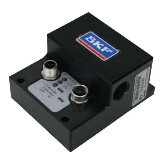
1 Connections for aerosol lines 2 Connection for supply voltage and analogue signal 3 Connection for BUS or Teach adapter SKF Lubri c ati o n Systems Germany GmbH 4 LED indicator for operating voltage AM1000 5 LED indicator for signals... -
Page 17: Functional Description
The Aerosol Monitor AM1000 is a scattered- monitor to the BUS system of an SKF MMS light monitor mounted into the aerosol line system Digital Super. Thus the MMS system between the aerosol generator and the receives information, for example regarding lubrication point of an MMS system. -
Page 18: Autonomous Operation With Teach Function
The parameters of the laser diode used with measuring chamber again, the laser will be the AM1000 have been optimized for a long switched on automatically. To be able to use the measuring signal to its durability, which is normally greater than the life of the application to be monitored. -
Page 19: Technical Data
4. Technical data 4. Technical data Aerosol Monitor AM1000, characteristics Designation Unit Medium Aerosol for MMS Typical diameter of droplet μm 0.5 to 5 Operating pressure, aerosol 4 to 10 Flow rate Nl/min max. 800 Connections: - Aerosol line for hose Ø 12 x 1, blue hose colour... -
Page 20: Assembly
Prior to performing work, the eye damage and IEC 364. Aerosol Monitor must be discon- Work on the open AM1000 is nected from the power supply. permitted only when the unit is Before erection and assembling of the Aero- Works on the Aerosol Monitor may deenergised. -
Page 21: Coniguration
BUS system of the MMS system settings can be leant from the associated Digital Super, the device must be configured operating instructions. If necessary, con- via the DIP switches located on the control tact an SKF service point. printed circuit board. - Page 22 5. Assembly DIP switches, Fig. 3 MMS systems Digital Super with connected Aerosol Monitor, Fig. 4 Gasket Digital Super UFD10-02x Digital Super UFD20-02x PARAMETER PARAMETER PARAMETER System 1 System 1 System 2 1 2 3 4 1 2 3 4 1 2 3 4 BUS cable BUS cable...
- Page 23 To ensure proper signal transmission, PROFIBUS cables must be terminated on deactivated both sides of a PROFIBUS segment by a BUS terminal. In case of the AM1000 the terminating resistor is integrated in the device and can be switched on or off via DIP switch 1. ATTENTION Make sure to avoid accidentally installed terminating resistors.
-
Page 24: Aerosol Monitor Am1000, Connecting Dimensions, Mounting Bores And Minimum Assembly Dimensions
5. Assembly 5.3 Aerosol Monitor AM1000, connecting dimensions, mounting bores and minimum assembly dimensions Aerosol Monitor AM1000 - Mounting bores and minimum assembly dimensions, Fig. 5 Mounting template, Fig. 6 33,5 Ø 5,5 (4 x) Ø5,5 Minimum assembly dimensions B = width:... -
Page 25: Set-Up
5. Assembly 5.4 Set-up see Fig. 5 to Fig. 7 Mount the Aerosol Monitor to a vertical Aerosol Monitor with mounted lines, Fig. 7 surface in such way that the Aerosol lines run horizontally. During operation the monitor's position must remain the same. Aerosol lines Aerosol lines Protect the Aerosol Monitor against hu-... -
Page 26: Connection Of Aerosol Lines
(4). Fully insert tube (1) into the col- There may be used aerosol lines only SKF recommends the use of opaque Aerosol let chuck (4) of the SKF plug-in connector that suit an operating pressure of at least lines. To obtain an optimum signal behaviour... - Page 27 5. Assembly • Before reassembly, the tube end of the ATTENTION Plug-in connector for plastic tubes, Fig. 8 aerosol line to be used again must be cut Make sure to insert the tube up to the by at least 7 mm to ensure safe function mechanical stop in order to avoid a gap, of the collet (5) of the chuck (4).
-
Page 28: Electrical Connection
5. Assembly 5.6 Electrical connection 5.6.1 Power supply and analogous power signal see Table. 2 The left plug of the Aerosol Monitor (pin Pin assignment for operating voltage and analogous signal, Table 2 contact) has been provided for connection of the operating voltage and the analogous Contact Assignment Pin coupling... -
Page 29: Bus Connection / Teach Adapter
5. Assembly 5.6.2 BUS connection / Teach adapter see Fig. 11 The right contact of the Aerosol Monitor In the left part of Fig. 4 the line terminal To connect the Teach adapter, the screw cap (socket contact) has been provided for con- must be activated in the Digital Super control must be removed from the right contact nection of the BUS connection to the MMS... -
Page 30: Notes Related To The Type
Type identification plate Fig. 9 Article 4 (1) (a) (i) and is therefore excluded from the scope of application of Pressure Equipment Directive 2014/35/EU following Article 4 (3). SKF Lubri c ati o n Systems Germany GmbH AM1000 0100xxxxxx Made in Germany... -
Page 31: Operation
6. Operation 6. Operation 6.1 Autonomous operation 6.3 Operation with connection to the BUS system of an MMS system type Digital Super To operate the Aerosol Monitor autono- LED display, Fig. 10 mously there is available an analogous current signal (4...20 mA) that indicates the When connecting the Aerosol Monitor to prevailing aerosol density. - Page 32 Signal LED flashes to the factory the signal and BUS LEDs and BUS LED flashes 4x ing range of the AM1000 6x red setting light up, then release the white to a signal of 4 - 20 mA.
-
Page 33: Maintenance
Make sure to avoid touching component connectors or conduc- tors inside the device. ATTENTION Only original SKF spare parts may be used. Unauthorized modification as well as a use Disassembly of the product or of single of non-original SKF spare parts and aux-... -
Page 34: Troubleshooting
The system is connected correctly. If it is not possible to remedy the mal- function, please contact the SKF Service o The BUS connection has been installed Department. correctly. When operating the Aerosol Monitor with... - Page 35 8. Troubleshooting Possible faults when operating the Aerosol Monitor, Table 5 Fault Cause Remedy Autonomous operation or operation with connection to the BUS system of an MMS system Digital Super Analogous value 4 mA No aerosol available • Check the MMS system always No useful Teach setting •...
-
Page 36: Shutdown And Disposal
The product can also be returned for dis- disconnecting it from the power supply. Note follow the applicable rules and regulations posal to SKF Lubrication Systems Germany the instructions given in chapter 5, on the disposal of contaminated means of GmbH, in which case the customer is re- Installation. -
Page 37: Accessories
UFZ.0369 UFZ.0375 UFZ.0368 UFZ.0374 T-junction M12x1 UFZ.0373 for BUS continuation when using two AM1000 on the UFD 20-02x Connection line, 5 m with M12x1 coupling and moulded cable 179-990-600 with M12x1 elbow coupling and moulded cable 179-990-601 Aerosol hose line Ø 12x1, 1 m long, hose colour State total length in the order. -
Page 38: Spare Parts
11. Spare parts 11. Spare parts Accessories of the Aerosol Monitor AM1000 Designation Quantity Order no. AM1000- gasket of bottom cover AM1000.09 AM1000- mounting screws of bottom cover 1 (needed 4x) DIN7991-M4x10-8.8 Plug-in connector UFZ.0428... - Page 39 Notes...
- Page 40 Not all lubricants are suitable for use in centralized lubrication systems. SKF does offer an inspec- tion service to test customer supplied lubricant to determine if it can be used in a centralized lubri- cation system.
Need help?
Do you have a question about the AM1000 and is the answer not in the manual?
Questions and answers