Advertisement
3/9/2017
SEADOO KIT Depth Finder
Part number (SKU) : 295100679
Product:
Project no:
Instruction Sheet P/N:
Revision no:
Revision date:
Item covered:
PRIOR TO INSTALLATION, PLEASE VERIFY IF A REVISED VERSION OF THIS INSTRUCTION
SHEET IS AVAILABLE ON KNOWLEDGE CENTER.
The following symbols may be used in this document:
WARNING
Indicates a hazardous situation which, if not avoided, could result in death or serious injury.
CAUTION: Indicates a hazard situation which, if not avoided, could result in minor or
moderate injury.
NOTICE
Indicates an instruction which, if not followed, could severely damage vehicle
components or other property.
WARNING
For safety reasons, this kit must be installed by an authorized BRP dealer.
This kit is designed for specific applicable models only (authorized BRP dealers will confirm
model(s)). It is not recommended for units other than the one (those) for which it was sold.
This instruction sheet MUST be given to the purchaser.
Should removal of a locking device (e.g. lock tabs, selflocking fasteners, etc.) be required
when undergoing disassembly/assembly, always replace with a new one.
Torque wrench tightening specifications must be strictly adhered to.
NOTE: The illustrations in this document show typical construction of the different assemblies and
may not reproduce the full detail or exact shape of the parts; however, they represent parts that have
the same or similar function.
Installation time is approximately 1.0 hour.
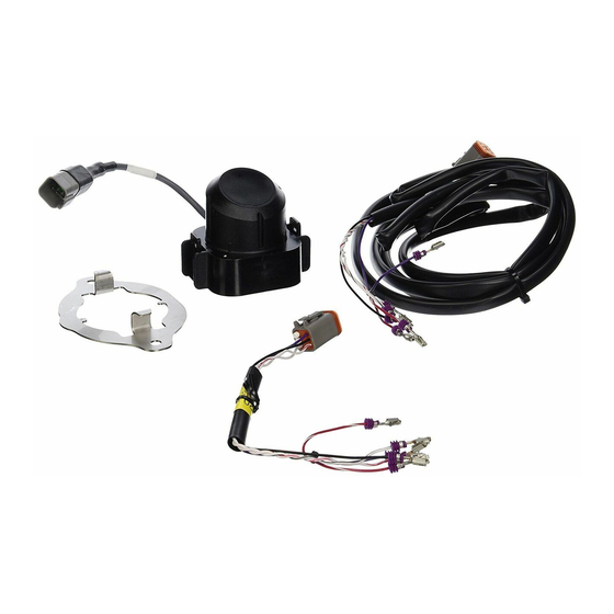
PARTS TO BE INSTALLED
Item
http://instructions.brp.com/content/instructionsheet/en_CA/einstructiondetails.html#articleNo=kA0a0000000l0rxCAA&lang=en_CA&title=SEADOO%20KIT...
einstructiondetails
SeaDoo_watercraft
487802049
487802049
Depth Finder (Kit P/N : 295100679)
Description
Part Number QTY
1/16
Advertisement
Table of Contents

Related Manuals for Sea-doo 295100679


Summary of Contents for Sea-doo 295100679
- Page 1 3/9/2017 einstructiondetails SEADOO KIT Depth Finder Part number (SKU) : 295100679 Product: SeaDoo_watercraft Project no: 487802049 Instruction Sheet P/N: 487802049 Revision no: Revision date: Item covered: Depth Finder (Kit P/N : 295100679) PRIOR TO INSTALLATION, PLEASE VERIFY IF A REVISED VERSION OF THIS INSTRUCTION SHEET IS AVAILABLE ON KNOWLEDGE CENTER. The following symbols may be used in this document: WARNING Indicates a hazardous situation which, if not avoided, could result in death or serious injury. CAUTION: Indicates a hazard situation which, if not avoided, could result in minor or moderate injury. NOTICE Indicates an instruction which, if not followed, could severely damage vehicle components or other property. WARNING For safety reasons, this kit must be installed by an authorized BRP dealer. This kit is designed for specific applicable models only (authorized BRP dealers will confirm model(s)). It is not recommended for units other than the one (those) for which it was sold. This instruction sheet MUST be given to the purchaser. Should removal of a locking device (e.g. lock tabs, selflocking fasteners, etc.) be required when undergoing disassembly/assembly, always replace with a new one. Torque wrench tightening specifications must be strictly adhered to. NOTE: The illustrations in this document show typical construction of the different assemblies and may not reproduce the full detail or exact shape of the parts; however, they represent parts that have the same or similar function. Installation time is approximately 1.0 hour. PARTS TO BE INSTALLED...
- Page 2 3/9/2017 einstructiondetails Depth Finder 278002954 Gel Pad 293550042 Depth Finder Support 278002495 Depth Finder Base Support 278001994 Wiring Harness 278002571 3 Amp Mini Fuse 710001008 http://instructions.brp.com/content/instructionsheet/en_CA/einstructiondetails.html#articleNo=kA0a0000000l0rxCAA&lang=en_CA&title=SEADOO%20KIT… 2/16...
-
Page 3: Vehicle Preparation
3/9/2017 einstructiondetails M6 x 20 Plastite Hexagonal 243162060 Screw Locking Tie 414115200 VEHICLE PREPARATION NOTE: Refer to appropriate Shop Manual. SPARK Models : (Type B) Remove the body. Unplug the battery. Disconnect BLACK () battery cable then the RED (+) cable. WARNING Always disconnect battery cables exactly in the specified order. GTI, GTS, GTR, WAKE 155 and RXT Models : (Type B) or (Type C) Open the front trim. Remove access panel to access to the battery. Unplug the battery. Disconnect BLACK () battery cable then the RED (+) cable. WARNING Always disconnect battery cables exactly in the specified order. Remove seat. GTX and RXT with suspension Models : (Type A) (Models 2015 and before) Open the rearward boarding platform. Remove the RH storage tray (starboard). Unplug the battery. Disconnect BLACK () battery cable then the RED (+) cable. WARNING Always disconnect battery cables exactly in the specified order. GTX, RXT and WAKE PRO Models WITHOUT suspension WITH rear access panels: (Type A) Open the RH rear access panels. Remove the RH storage tray (starboard). Unplug the battery. Disconnect BLACK () battery cable then the RED (+) cable. http://instructions.brp.com/content/instructionsheet/en_CA/einstructiondetails.html#articleNo=kA0a0000000l0rxCAA&lang=en_CA&title=SEADOO%20KIT… 3/16... -
Page 4: Installation Instructions
3/9/2017 einstructiondetails WARNING Always disconnect battery cables exactly in the specified order. GTX, RXT and WAKE PRO Models WITHOUT suspension WITHOUT rear access panels (Type C) Open seat. INSTALLATION INSTRUCTIONS Depth Finder Support Installation 1. Locate area where depth finder is to be installed. See following illustrations for your type of vehicle. To reach depth finder installation location, remove the following components, if applicable to your vehicle model: Lower deck Rear grab handle Coolant bottle Exhaust hose from engine Exhaust Breather hose from engine air intake Rear engine air intake. Depth Finder Installation All Models: 1. Install gel pad on depth finder. 1.1 Place the flat side of depth finder on a level surface. 1.2 Clean the concave surface of depth finder. 1.3 Remove both protectors from gel pad. 1.4 Apply gel pad on depth finder. NOTICE Make sure not to trap air between gel pad and depth finder. Otherwise, the device may not work properly. 1. Gel pad [P2] 2. Depth finder [P1] (Type A) Under the battery (2015 and before) Remove the top of the electrical components support and put away. 1. Remove and keep screws securing battery holder to battery holder base (one on each side). http://instructions.brp.com/content/instructionsheet/en_CA/einstructiondetails.html#articleNo=kA0a0000000l0rxCAA&lang=en_CA&title=SEADOO%20KIT… 4/16... -
Page 5: Tightening Torque
3/9/2017 einstructiondetails PARTS REMOVED FOR CLARITY 1. Retaining screws 2. Battery holder 2. Unplug vent hose from battery. 3. Remove battery (with battery holder) from vehicle. 4. Install depth finder into battery holder base with the harness toward the pump. 5. Push on the depth finder until both locking tabs are locked. Make sure depth finder locking tabs are well engaged into support bracket. 1. Locking tabs 2. Battery holder base 6. Route the depth finder harness in the battery holder base groove. 7. Plug vent hose to the top of battery. Make sure vent hose is not pinched or bent. 8. Install the battery and support in vehicle using preciously removed M8 x 40 screws. 9. Tighten battery holder screws to specification. Tightening torque Battery holder screws 14 ± 2 N•m (124 ± 18 lbf•in) (Type B) With screwed bracket NOTE: Ensure to properly orient the support rounded notch towards the center of the hull. 1. Support rounded notch http://instructions.brp.com/content/instructionsheet/en_CA/einstructiondetails.html#articleNo=kA0a0000000l0rxCAA&lang=en_CA&title=SEADOO%20KIT… 5/16... -
Page 6: Service Products
3/9/2017 einstructiondetails Tightening torque M6 x 20 Plastite Hexagonal Screw [P7] 7 ± .5 N•m (62 ± 4 lbf•in) 1. Install the depth finder into its support with harness pointing towards center of hull. Squeeze retaining tabs to ease insertion. 2. Push on the depth finder until both locking tabs are locked. 1. Depth finder 2. Locking tabs locked (Type C) With glued base 1. Install depth finder support as per following illustrations. service products Isopropyl alcohol Clean inside of hull at depth finder support mounting area 5 minute epoxy glue Glue depth finder support to inside of hull NOTE: In following illustration, some hoses are not shown for clarity of illustration. TYPICAL HULL PREPARATION 1. Clean hull here 2. Exhaust temperature sensor 3. Bailer assembly 2. Prepare epoxy glue as per manufacturers' instructions. WARNING When mixing and applying epoxy glue, always refer to manufacturers instructions. 3. Apply generous amount of epoxy glue to base of depth finder support. http://instructions.brp.com/content/instructionsheet/en_CA/einstructiondetails.html#articleNo=kA0a0000000l0rxCAA&lang=en_CA&title=SEADOO%20KIT… 6/16... -
Page 7: Electrical Connections
3/9/2017 einstructiondetails DEPTH FINDER SUPPORT PREPARATION 1. Top of depth finder support [P4] 2. Generous amount of epoxy glue applied here (bottom of support) DEPTH FINDER SUPPORT INSTALLATION 1. Longitudinal axis of watercraft 2. Depth finder locking tabs 3. High side of depth finder support towards keel of watercraft 4. Allow sufficient time for epoxy glue to set before installing depth finder. Refer to manufacturers' instructions. Electrical Connections 2016 and up Refer to shop manual 900 HO Models NOTE: Install (P/N 295100599) following the procedure included.. Accessory Fuse Box Preparation 1. Disconnect and remove accessory fuse box from battery. See following illustrations. http://instructions.brp.com/content/instructionsheet/en_CA/einstructiondetails.html#articleNo=kA0a0000000l0rxCAA&lang=en_CA&title=SEADOO%20KIT… 7/16... - Page 8 3/9/2017 einstructiondetails 1. Long accessory fuse box harness connector 2. Vehicle DLC holder 1. Short accessory fuse box harness connector 2. Vehicle DLC connector TYPICAL 1. Release fuse box from its support here 2. Remove accessory fuse box cover. 3. Remove all bus bars from accessory fuse box. 1. Bus bars to remove 4. Locate and remove the following seal plugs from back of accessory fuse box: A3, B3, C3, D3, D5, and D6. NOTE: Fuse box contact coordinates are molded on the back of the fuse box. http://instructions.brp.com/content/instructionsheet/en_CA/einstructiondetails.html#articleNo=kA0a0000000l0rxCAA&lang=en_CA&title=SEADOO%20KIT… 8/16...
- Page 9 3/9/2017 einstructiondetails CONTACT COORDINATES 5. Insert wire terminals of wiring harness [P5] into fuse box contact coordinates as per following table. Wiring Harness (P5) connection to fuse box Wire color Fuse box contact position Red / White wire Black White / Black White / Red Purple 6. Complete fuse box connection and installation as per following illustrations. 1. Install bus bars 2. Install fuse [P6] Step 1:. Install fuse box cover http://instructions.brp.com/content/instructionsheet/en_CA/einstructiondetails.html#articleNo=kA0a0000000l0rxCAA&lang=en_CA&title=SEADOO%20KIT… 9/16...
- Page 10 3/9/2017 einstructiondetails Step 2:. Install fuse box on its support SHORT FUSE BOX HARNESS CONNECTION 1. Short accessory fuse box harness connector 2. Vehicle DLC connector LONG FUSE BOX HARNESS CONNECTION 1. Long accessory fuse box harness connector 2. Vehicle DLC holder 1. Accessory fuse box 2. Depth finder location 3. Wiring harness routing NOTE: The depth finder wiring harness is routed behind both engine mounts in the bottom of the hull, under the engine. http://instructions.brp.com/content/instructionsheet/en_CA/einstructiondetails.html#articleNo=kA0a0000000l0rxCAA&lang=en_CA&title=SEADOO%20KIT… 10/16...
- Page 11 3/9/2017 einstructiondetails 1. LH rear engine support 2. Steering cable 1. Steering cable 2. LH front engine support http://instructions.brp.com/content/instructionsheet/en_CA/einstructiondetails.html#articleNo=kA0a0000000l0rxCAA&lang=en_CA&title=SEADOO%20KIT… 11/16...
-
Page 12: Electric Connection
3/9/2017 einstructiondetails 1. Steering cable 2. Fuse box 7. Reconnect battery. WARNING Always reconnect positive (+) battery terminal first, negative () terminal last. Step 1:. Reconnect positive (+) terminal first Step 2:. Reconnect negative () terminal last 8. Carry out a test of the depth finder operation, refer to DRY TESTING OF DEPTH FINDER. Electric Connection All Models except 900 HO Models (2015 and before) 1. Disconnect BLACK () battery cable then the RED (+) cable. WARNING Always disconnect battery cables exactly in the specified order. http://instructions.brp.com/content/instructionsheet/en_CA/einstructiondetails.html#articleNo=kA0a0000000l0rxCAA&lang=en_CA&title=SEADOO%20KIT… 12/16... - Page 13 3/9/2017 einstructiondetails TYPICAL 1. BLACK () cable first 2. RED (+) cable last 2. Lift and push top of electrical component support to unlock it from battery holder. Move support aside to make room. TYPICAL TOP VIEW 1. Electrical component support 1. Lower receptacle 2. Upper retaining tab All Models WITHOUT rear access panels Route wiring harness [P5] from fuse box to depth finder along main wiring harness. Secure it using locking ties [P8] every 400 mm (16 in) along the way. NOTICE Keep wire harness away from sharp edges and moving, rotating or hot parts. Regroup the wire excess near to the battery and secure with locking ties [P8]. All Models WITH rear access panels Regroup the wire excess near to the battery and secure with locking ties [P8]. http://instructions.brp.com/content/instructionsheet/en_CA/einstructiondetails.html#articleNo=kA0a0000000l0rxCAA&lang=en_CA&title=SEADOO%20KIT… 13/16...
- Page 14 3/9/2017 einstructiondetails 1. Connect depth finder connector to new wiring harness. 2. Connect RED (+) battery cable first, then the BLACK () cable. WARNING Always connect battery cables exactly in the specified order. TYPICAL 1. RED (+) cable first 2. BLACK () cable last 3. Refer to DRY TESTING OF DEPTH FINDER to ensure depth finder operation. 4. Reinstall all other removed parts. WARNING Never use the depth finder as a warning device to ride in shallow water. Use it as a navigation guide only. Not to be used to get precise navigation data. DRY TESTING OF DEPTH FINDER All models 1. You need a container (cup, glass or an empty watercraft security containing). 2. Remove lid from the watercraft safety equipment container. Empty the container. 3. Install the tether cord on the engine cutoff switch. 4. Momentarily press the start button to energize the electrical system. 5. Repeatedly press the MODE button on the multifunction gauge until DEPTH is displayed. 6. Place the empty safety equipment container on lower hull directly beneath the depth sounder. http://instructions.brp.com/content/instructionsheet/en_CA/einstructiondetails.html#articleNo=kA0a0000000l0rxCAA&lang=en_CA&title=SEADOO%20KIT… 14/16...
- Page 15 3/9/2017 einstructiondetails Please note that an empty metal container can also be used to perform this test. The gauge should provide a reading. The reading may increase and decrease during the test however, the gauge will always provide a numerical depth indication if the depth finder is working properly. CORRECT VIEW ON GAUGE IF DEPTH SOUNDER IS WORKING PROPERLY If depth finder provides a numerical indication as previously illustrated, no more action is required. If depth finder provides an indication of only dashes (no numbers), there may be air trapped between the depth finder and the gel pad. If this is the case, the gel pad must be replaced. INCORRECT VIEW ON GAUGE REINSTALLATION OF DEPTH FINDER Since the gauge provided a bad reading, it is possible that there is an air gap between the base of the depth finder and the hull. Carry out the following steps. 1. Remove depth finder. 2. Remove gel pad from depth finder. 3. Thoroughly clean the area where the depth finder will be reinstalled. 4. Apply gel pad to the face of the depth finder so it covers the entire mating surface. http://instructions.brp.com/content/instructionsheet/en_CA/einstructiondetails.html#articleNo=kA0a0000000l0rxCAA&lang=en_CA&title=SEADOO%20KIT… 15/16...
- Page 16 3/9/2017 einstructiondetails 1. Gel pad [P6] 2. Depth finder [P1] 5. Reinstall depth finder. 6. Dry test depth finder to ensure you obtain a proper reading. Depth Finder Troubleshooting Depth finder TROUBLESHOOTING SYMPTOM POSSIBLE CAUSE REMEDY Depth finder not connected. Connect it properly. 12 V or ground wire open to Check fuse and wiring NOTHING is displayed in the depth finder. harnesses. information center Check WHITE/BLACK and Problem with the WHITE/RED wires to CAN communication link wires. busbars in fuse box. Launch watercraft in water and Watercraft is not in water. recheck. (ft or m) is displayed and There is air between gel pad SENSOR is blinking after self Remove depth finder. Replace and depth finder or between test for 5 seconds gel pad. depth finder and hull. Depth finder is defective. Try a new depth finder. Reinstall all removed components. http://instructions.brp.com/content/instructionsheet/en_CA/einstructiondetails.html#articleNo=kA0a0000000l0rxCAA&lang=en_CA&title=SEADOO%20KIT…...
Need help?
Do you have a question about the 295100679 and is the answer not in the manual?
Questions and answers