Table of Contents
Advertisement
Quick Links
Advertisement
Table of Contents

Related Manuals for Maxton EMV10

Summary of Contents for Maxton EMV10
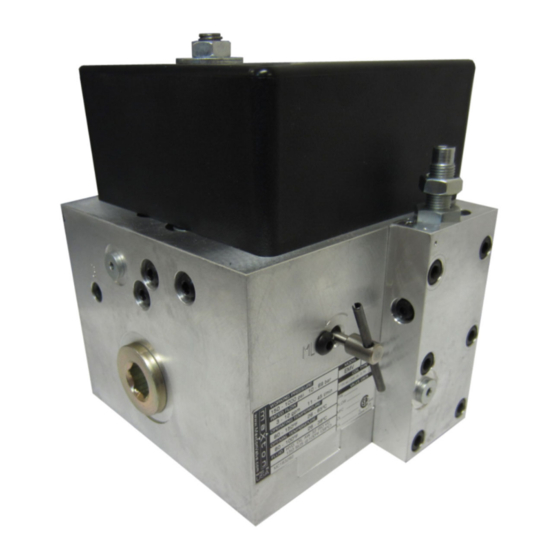
- Page 2 INTRODUCTION AND FEATURES The Maxton EMV10 Electronic Motor Valve was designed to meet a growing demand for low use limited access (LULA), handicapped and residential hydraulic elevator applications. The EMV10 combines hydraulic and electronic control to provide excellent ride quality. The EMV10 has all the features found in a commercial hydraulic control valves plus electronic safety control and adjustments allowing quick set up and easy problem analysis.
-
Page 3: Specifications
SPECIFICATIONS EMV10 SPECIFICATIONS IMPERIAL METRIC Flow Range 3 - 12 gpm 11 - 45 lpm Operating Pressure 150 psi 10 bar 1000 psi 69 bar Line Ports 3/4” NPT Gauge Ports “B” 1/8” NPT Pressure Port “S” 1/8” NPT Operating Temperature 80 - 150ºF... -
Page 4: Valve Dimensions
VALVE DIMENSIONS PORT LOCATIONS: Use pipe or hose fittings with the following port locations as shown: Pump: ¾” NPT Jack: ¾” NPT Tank: ¾” NPT 3-7/32" (81.8 mm) Valve 3-1/16" (77.8 mm) 2” (51 mm) dia. 2-7/16" Cut out of tank lid (61.9 mm) .730”... -
Page 5: Slowdown Distance
SLOWDOWN DISTANCE CONTROL SIGNAL SEQUENCE Installer to provide U, UL, D, and DL signals from main elevator controller to VCB (Valve Control Board). UL: For up travel, turn on at pump start, turn off to stop. With UL signal on and pump running, car moves up at leveling speed. For “soft stop” pump should run about one half second after UL signal is turned off. -
Page 6: Field Wiring Diagram
Failure to correctly follow the recommended procedures may result in damage and/or a hazardous condition. Verify all voltages before applying power. Incorrect voltages will damage the EMV10 control board. Dedicated power supply must be regulated at +24VDC and Rated at 3.2 amps minimum. - Page 7 Verify all voltages before applying power. Incorrect voltages will damage the EMV10 control board. Dedicated power supply must be regulated at +24VDC and Rated at 3.2 amps minimum. Interface to the EMV10 uses Maxton Field Interface Cable. Color Coded wires are used to identify each electrical connection. Connect each wire to the elevator controller function as described below.
- Page 8 VALVE CONTROLLER BOARD FEATURES Motor & Sensor Interface Connector “POWER” Connector LED INDICATOR “DV” COIL LED INDICATOR Solenoid Coil Connector LCD Display Programming Menu Navigation Port Buttons VALVE SET UP THE INFORMATION PRESENTED HEREIN IS FOR USE BY SKILLED HYDRAULIC ELEVATOR PROFESSIONALS FACTORY SETTING: All valves are factory tested and set to the job specifications provided.
-
Page 9: Display Menu
DISPLAY MENU Notification Press “UP or DOWN” button to cycle through the menu MAIN MENU Flashing cursor indicates current setting DISPLAY FUNCTION DESCRIPTION Upon power up, the Main Screen will Display. Screen must be active for Main Screen valve to operate in run mode. - Page 10 (Only if instructed by size setting by pressing the “UP” button to increase sizing or “DOWN” button Maxton tech support) to decrease sizing until the car reaches 0.3fpm Press “LEFT/RIGHT” button to cycle to “Y” (yes) and press the “ENTER”...
- Page 11 Clogged orifices, strainer. Check for oil contamination. move. Up Compensator Spool jammed. Up Compensator Spring broken. Up Compensator Valve not closing. Call Maxton for Assistance Ride Quality setting. Change Ride Quality Setting. P7 , 8 Sizing position incorrect. Call Maxton For Assistance Up Acceleration rough.
- Page 12 Car slowly creeps down Replace solenoid coil, if necessary. when down call registered Check Open Orifice Clogged Remove and Flush Check Open Orifice, Call Maxton For Assistance MFC malfunction Replace MFC, Call Maxton For Assistance Leak at jack or line Close line shut-off valve.
- Page 13 After a run is complete car moves down 2-8" during pressure relief routine. Check Piston not closed Call Maxton For Assistance Erratic up and down Check sensor cavity for oil. Clean with contact cleaner and dry with movement Sensor unable to read encoder disk...
-
Page 14: Error History
ERROR HISTORY The valve controller program incorporates self diagnostic routines designed to identify conditions that can result in incorrect or abnormal valve operation. The diagnostic routines have the ability to auto-correct most conditions that may be encountered. Error History: If an error condition occurs the VCB will momentarily stop car movement, interrupt the pump operation and display an error.
Need help?
Do you have a question about the EMV10 and is the answer not in the manual?
Questions and answers