Subscribe to Our Youtube Channel
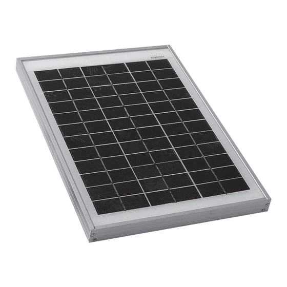
Summary of Contents for Solar Technology International PV Logic STP005
- Page 1 PV Logic ® Rigid User manual Rigid Solar Panels 5wp/10wp/20wp/30wp/45wp/60wp/80wp/100wp/120wp/150wp/200wp Technical helpline 01684 774 000 Important: please read before first use.
- Page 2 PV Logic Rigid kit contents TECHNICAL HELPLINE 01684 774000 Letters after item descriptions refer to the picture opposite. Basic Kits Basic Kits are available with the following contents: STP080 STP200 1 x 80wp Solar panel (a) 1 x 200wp Solar panel (a) STP005 STP030 1 x 4m cable (h) 1 x 4m cable (h) 1 x 5wp Solar panel (a) 1 x 30wp Solar panel (a) 1 x In line fuse / holder (i) 1 x In line fuse / holder (i) 1 x 4m cable (h) 1 x 4m cable (h) 6 x Ring terminals (l) 6 x Ring terminals (l) 1 x In line fuse / holder (i) 1 x In line fuse / holder (i) 1 x Instruction sheet (m) 1 x Instruction sheet (m) 2 x Crocodile clips (k) 6 x Ring terminals (l) 6 x Ring terminals (l) 1 x Instruction sheet (m) STP100 1 x Instruction sheet (m) 1 x 100wp Solar panel (a) Mono High Density Kits STP045 1 x 4m cable (h) STP010...
- Page 3 TECHNICAL HELPLINE 01684 774000 PV Logic ® User Manual Rigid User manual Rigid solar panels 5wp/10wp/20wp/30wp/45wp/60wp/80wp/100wp/120wp/150wp/200wp Important: please read before first use. Technical helpline 01684 774 000 Kit shown: STPMH080 Please read all instructions carefully before work begins IMPORTANT: When connecting a solar panel to a battery, it is always recommended that a voltage regulator is used to prevent both reverse current feed (at night) and overcharging of the battery. The only exception to this is the STP005 and STP010 because they are fitted with a reverse feed diode and if connected to battery size at or greater than 35Ah and 70Ah respectively will not overcharge because of each battery’s own impedance. Step 1: Fitting the cable to the solar panel (Cable pre fitted to 60wp to 150wp panels) 1.1 Remove the cover (A) from the terminal box on the rear of the solar panel 1.2 Panel sizes up to 30wp generally have the junction box style shown in Fig 1A. Panels 45wp and over have the syle shown in Fig 1B. Fitting the cable to both is similar but with the 3 terminal style shown in...
- Page 4 6.3 Place the brackets onto the surface and push down so the bonding In the event of a successful warranty claim in both cases, Solar Technology agent just squeezes out beneath the edge of the bracket base. International will, at its discretion provide one of the following remedies; 1. Quickly insert the screws through the bracket holes and tighten up Replace the defective solar panel or 2. Refund the percentage of the cost of but not too tight so it compresses the bracket against the sealant. the solar panel to the customer representing the percentage of the time period between new and year 10 and in the case of a claim on the cell performance a 6.4 Leave the brackets to cure for 24 hours and then fully tighten the percentage will be paid according to the power output less than 80%. screws. Solar Technology International Ltd does not accept liability for any 3rd party 6.5 The panel can then be fitted to the bracket and the cable gland damage how so ever caused or any costs associated with the return of faulty installed as per 5.4 and 5.6 above products. 6.6 The charge controller should then be fitted as per Step 2, 3 and 4. We want your photos and videos! Here is your chance for you and your solar panel to be a star! Just send in pics or videos of you and your solar panel in a great location and if selected we will not only give you ever lasting recognition on our online favourite users wall of fame but we will send you a Freeloader Sixer, 6000mAH solar power bank worth £70 completely free! Please send to hello@solartechnology.co.uk including your address details and best of luck! Note – we cannot guarantee to publish every entry and only those selected by our marketing department for publication will be awarded a Sixer. By providing your images you automatically grant us the right to use these images or videos howsoever we see fit. Solar Technology International Limited Unit 6, Station drive, Bredon, Tewkesbury GL20 7HH...


Need help?
Do you have a question about the PV Logic STP005 and is the answer not in the manual?
Questions and answers