Advertisement
Quick Links
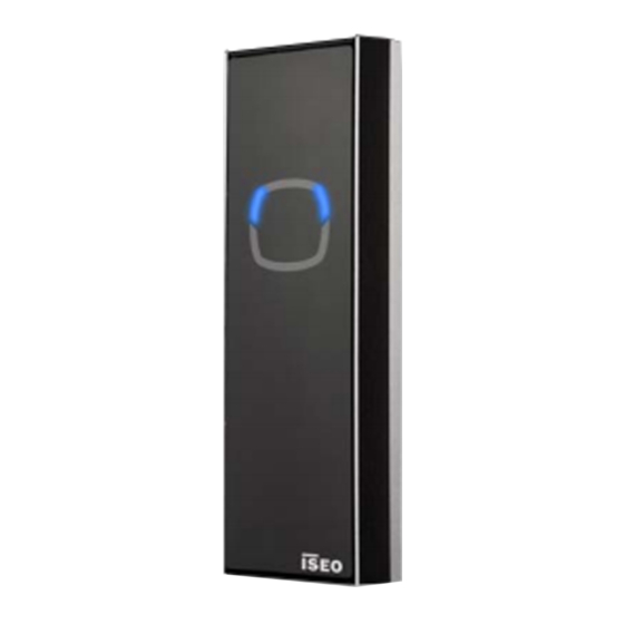
Stylos 2
INSTALLATION GUIDE (EN)
i s e o . c o m
Non contractual document. Subject to change. Cod. 60000STY2LV01.4 - 08/06/2020
Stylos 2 Credential Reader inst. guide (EN) - © 2020 Iseo Serrature S.p.a. - www.iseo.com
TECHNICAL DATA
Power Supply: 8÷30 VDC 3W MAX
RFID: frequency 13,553 - 13,567 MHz, maximum magnetic field: 0,89 µA/m (measured at 10m at the
maximum power capacity).
Only for devices with on-board Bluetooth radio: frequecy 2,40 - 2,4835 GHz, maximum power: 5,25 mW.
Operating temperature: -20°C + 60°C
3V
Lithium
Lithium Battery
CR2032
CR2032 - 3V
Risk of explosion if the battery is replaced with an incorrect type.
Dispose of batteries according to your local environmental laws and guidelines.
Battery replacement must be carried out by qualified technical staff.
For the replacement battery procedure, read the user manual available at app.iseo.com.
2. DISASSEMBLING
Disconnect the power before opening the device.
3.1 STAND-ALONE GATE ELECTRICAL CONNECTIONS
Power supply: 8 ÷30 VDC 3W
MAX
Minimum/maximum cross-section
of the cables is:
0.20÷1.5
mm²
(24÷15AWG).
LEGEND:
J2.1/2/3/4 = Power supply/Lockbus
JPS = System Jumper (reserved)
S1 = Programming button
JP 0/2/4/6 = Bus Address Jumpers
BUS
JP
JP
JP
JP
FUNCTION
6
4
2
0
ADDRESS
(Master)
ADDRESS 0 =
(slave)
ADDRESS 2 =
ADDRESS 4 =
(slave)
(slave)
ADDRESS 6 =
Iseo Serrature s.p.a
®
Via San Girolamo 13
25055 Pisogne (BS)
ITALY
Tel. +39 0364 8821
iseo@iseo.com
ELECTRONIC SUPPORT SERVICE
iseozero1.com
LOCKBUS
(Communication Channel)
Back side view
POSITIVE (+) Power Supply
Circuit board
NEGATIVE (-) GND
J2.
J2.
J2.
J2.
1
2
3
4
JPS
JP
JP
JP
JP
6
4
2
0
JP
JP
6
4
S1
BUS
ADDRESS
WARNINGS
Read this manual prior to use the device in order to ensure a safe and proper use.
Preserve this manual as future reference.
The installation and maintanance of the device must be carried out by qualified technical staff, adequately
trained by ISEO.
The instructions should be carefully followed during installation. These instructions and any maintenance
instructions should be passed on by the installer to the user.
No modifications of any kind are permitted, except for those described in these instructions.
The product must be destined only for the use for which it is expressly designed and therefore as a
credential reader for civil and industrial locations. Any other use is considered improper and dangerous.
The electrical connection must be made according to the constructor's instructions and respecting the
regulations in force.
In the event of a failure and/or poor operation, remove the power supply using the main switch and do not
tamper with it. For all repairs, exclusively contact a technical assistance center authorized by the constructor.
Disconnect the power supply before carrying out any technical service that involves opening or accessing
the internal parts of the product.
1. VERSIONS AND DIMENSIONS
Credential reader
with led
A = 47,5mm
B = 17,5mm
C = 130mm
3. STAND-ALONE GATE SETTING
Back side view
Circuit board
J2.
J2.
J2.
J2.
1
2
3
4
JPS
JP
JP
JP
JP
6
4
2
0
4. READER/VALIDATOR SETTING
Back side view
Circuit board
J2.
J2.
J2.
J2.
1
2
3
4
J2.
J2.
J2.
J2.
1
2
3
4
JPS
JPS
JP
JP
JP
JP
JP
JP
6
4
2
0
2
0
S1
Spacer for wall
installation
A = 40mm
B = 10mm
C = 125mm
Only to set the Stylos 2 to be used as Stand-Alone
gate, you have to close, by a jumper, PIN 2 and 3 as
shown in the picture.
1
2
Fit the jumper when
the Stylos is OFF.
3
4
5
S1
Stylos as Stand-Alone gate = Address 0 (Master)
Stylos as Reader/Validator = Address 1
S1
For more information about Stylos and Atlas, refer to
the Atlas Installation Manual available at:
app.iseo.com.
EC Declarations of conformity available at:
https://www.iseo.com/it/en/download
This guide includes instruction
to configure the Stylos as
Stand-Alone
gate
or
as
Reader/Validator,
connected
to Atlas. Refer to the proper
section.
Advertisement

Related Manuals for Iseo Zero1 Stylos 2

Summary of Contents for Iseo Zero1 Stylos 2
- Page 1 Disconnect the power supply before carrying out any technical service that involves opening or accessing the internal parts of the product. Non contractual document. Subject to change. Cod. 60000STY2LV01.4 - 08/06/2020 Stylos 2 Credential Reader inst. guide (EN) - © 2020 Iseo Serrature S.p.a. - www.iseo.com 1. VERSIONS AND DIMENSIONS TECHNICAL DATA Power Supply: 8÷30 VDC 3W MAX...
- Page 2 Stylos User Manual available one button for 3 sec. J P 1 LC H J P 2 L P W J P 3 at app.iseo.com. Stylos Master address 0 Power supply 8 ÷ 24VDC 25W J P 1 LC H...
Need help?
Do you have a question about the Zero1 Stylos 2 and is the answer not in the manual?
Questions and answers