
Related Manuals for Magnetek LaserGuard2 LG2-H-4

Summary of Contents for Magnetek LaserGuard2 LG2-H-4
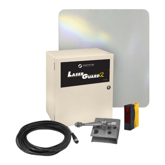
- Page 1 LaserGuard2 Laser Collision Avoidance System Distributed by Ergonomic Partners Sales@ErgonomicPartners.com Part Number: 147-20004 R1 www.ErgonomicPartners.com April 2015 Tel: (314) 884-8884 ©Copyright 2015 Magnetek Material Handling...
-
Page 2: Table Of Contents
Table of Contents Service Contact Information ........................3 Preface and Safety ..........................4 1.1. Product Safety Information ......................4 1.2. Product Warranty Information ....................... 4 1.3. DANGER, WARNING, CAUTION, and NOTE Statements ............5 ... -
Page 3: Service Contact Information
Magnetek Material Handling N49 W13650 Campbell Drive Menomonee Falls, WI 53051 Magnetek, Inc. has additional satellite locations for Canada and the United States. For more information, please visit http://www.magnetek.com. ©2015 MAGNETEK All rights reserved. This notice applies to all copyrighted materials included with this product, including, but not limited to, this manual and software embodied within the product. -
Page 4: Preface And Safety
It is the responsibility of the owners, users and operators of the Magnetek Products to know, understand and follow all of these requirements. It is the responsibility of the employer to make its employees aware of all of the above listed requirements and to make certain that all operators are properly trained. -
Page 5: Danger, Warning, Caution, And Note Statements
1.3. DANGER, WARNING, CAUTION, and NOTE Statements Read and understand this manual before installing, operating, or servicing this product. Install the product according to this manual and local codes. The following conventions indicate safety messages in this manual. Failure to heed these messages could cause fatal injury or damage products and related equipment and systems. -
Page 6: Collision Avoidance Unit Warnings
1.4. Collision Avoidance Unit Warnings WARNING Range detector relays should never be electrically or mechanically disabled to be ON or OFF for any crane motion. If the unit is for any reason disengaged or turned off the crane operating personnel must be notified immediately, and proper alternate precautions should be taken. -
Page 7: General System Information
Class 1 Laser Device The Magnetek Collision Avoidance System contains a Class 1 laser with a 660 nm wavelength. Although the laser is eye-safe, it is recommended that no one look directly into the laser with their eye close to the lens of the laser unit. -
Page 8: Optical Path Fault Detector
A rugged, fully adjustable mount is also supplied with the system, along with a reflective target. The target is mounted on the wall or other crane that is going to be protected by the collision avoidance system. The LSU contains three fully adjustable range detectors and a fault detector. The range detectors are adjustable to trip the relays from approximately 8 in. -
Page 9: System Specifications
2.6. System Specifications Laser Support Unit (LSU) Specification Laser LG2-H-4 LG2-L-4 LG2-H-4X LG2-L-4X Operating -30° to 55°C -30° to 70°C Temperature Operating Range 8 in.-150 ft. 85 - 264 VAC or 85 - 264 VAC or Input Voltage 9-36 VDC 9-36 VDC 120 - 370 VDC 120 - 370 VDC... -
Page 10: Installation Information
3. Installation Information NOTE: In the event that parts of an original LaserGuard system are used with the LaserGuard2, please refer to the LaserGuard2 Replacement Guide Application Bulletin on http://www.magnetek.com. CAUTION THE LASER CONTROL UNIT AND RELAYS ARE NOT RATED AS EXPLOSION PROOF. THE UNIT MUST NOT BE INSTALLED IN EXPLOSIVE ENVIRONMENTS UNLESS APPROPRIATE SECONDARY ENCLOSURE MEASURES ARE TAKEN. -
Page 11: Mechanical Installation
3.4. Mechanical Installation The Collision Avoidance System measures the distance between the laser unit's lens and the target surface. There must be no projections on the wall or the overhead crane that may extend in front of either (or both) the laser unit or the companion target. Make sure the laser is mounted such that nothing can come between the laser's view of the target. - Page 12 Figure 3: Mounting Bracket Dimensions (in mm) LaserGuard2 Instruction Manual April 2015 Page 12 of 31...
- Page 13 Figure 4: Mounting Instructions LaserGuard2 Instruction Manual April 2015 Page 13 of 31...
- Page 14 Install the laser and the target in the positions found the previous figure. Mount the laser securely to a solid surface so that the crane’s load or movement will not affect the laser’s alignment. The laser and laser support unit should also be mounted as close to the control panel as possible to minimize long cable runs.
- Page 15 Mounting of the reflector target is not as critical as the laser (refer to Figure 6). Figure 6: Target Dimensions LaserGuard2 Instruction Manual April 2015 Page 15 of 31...
- Page 16 Figure 7: Enclosure Dimensions A – 12.00 in (305 mm) G – 10.50 in (267 mm) B – 12.00 in (305 mm) H – 10.50 in (267 mm) C – 6.00 in (152 mm) M – 8.74 in (222 mm) D –...
-
Page 17: Electrical Installation
3.5. Electrical Installation The laser unit interface cable and all other wiring should be run in separate 1/2" or 3/4" conduit. Do not run any other cables in the same conduit with the laser head cable. A suitable disconnect should be provided by the installer. Run conduit between the laser support unit and the crane's control panel. - Page 18 Figure 10: Laser Support Unit Wiring for LG2-H-4 LaserGuard2 Instruction Manual April 2015 Page 18 of 31...
- Page 19 Figure 11: Laser Support Unit Wiring for LG2-L-4 LaserGuard2 Instruction Manual April 2015 Page 19 of 31...
- Page 20 Magnetek Customer Service. Turn on the power to the laser support unit and note that the green LED on the laser head is on continuously after a few seconds.
-
Page 21: Mechanical Alignment
3.6. Mechanical Alignment Loosen the bolt on the bottom of the mounting rod and the screw on the clamp so the laser head can be angled up and down, and from left to right with just enough friction so the laser head does not fall over on its own. -
Page 22: Troubleshooting
3.9. Troubleshooting NOTE: Please refer to Table 1 for the Laser Diagnostic LED Functions referred to in this section. If the green LED on the laser head flashes at 4Hz, the laser has short circuited. Replace the laser unit. Do not try to service it. - Page 23 Table 1: Laser Diagnostic LED Functions NOTE: See Figure 13 for LED locations. COLOR FUNCTION Laser Head Green Monitors voltage to the Laser Head Operating Display Normally ON. Laser Head Yellow Monitors target acquisition. Signal Normally ON when target is acquired. It turns off when the laser is off the target, out of range, or has a dirty lens.
-
Page 24: Installation Diagrams
4. Installation Diagrams Figure 13: Component Locations LaserGuard2 Instruction Manual April 2015 Page 24 of 31... - Page 25 Figure 14: LaserGuard2 Stepped Series 4 VFD Control, Protection in One Direction (Recommended) LaserGuard2 Instruction Manual April 2015 Page 25 of 31...
- Page 26 Figure 15: LaserGuard2 Crane Control, Protection in One Direction LaserGuard2 Instruction Manual April 2015 Page 26 of 31...
- Page 27 Figure 16: LaserGuard2 Crane Control with Timed Bypass, Protection in One Direction LaserGuard2 Instruction Manual April 2015 Page 27 of 31...
- Page 28 Figure 17: LaserGuard Magnetic Crane Control, Protection in Both Directions LaserGuard2 Instruction Manual April 2015 Page 28 of 31...
- Page 29 Figure 18: LaserGuard2 Stepped VFD Control, Protection in One Direction LaserGuard2 Instruction Manual April 2015 Page 29 of 31...
- Page 30 Figure 19: Typical LaserGuard2 Interface with Stepless VFD Control LaserGuard2 Instruction Manual April 2015 Page 30 of 31...
- Page 31 Figure 20: Typical LaserGuard2 Interface with P&H Stepless Control LaserGuard2 Instruction Manual April 2015 Page 31 of 31...
- Page 32 Addendum #: 147-20054 R0 February 2015 LaserGuard2 Systems LaserGuard2 Systems Using a Special Laser Addendum to: LaserGuard2 Collision Avoidance System Instruction Manual (147-20004) A special laser will be marked with a label to indicate it has a sensing distance that deviates from the standard distance of 5 to 150 ft.
- Page 33 Addendum #: 147-20066 R0 March 2015 LaserGuard2 Systems LaserGuard2 Systems Retrofit Addendum to: LaserGuard2 Collision Avoidance System Instruction Manual (147-20004) Parts of an older LaserGuard system and a new LaserGuard2 system can be used together and function properly, but it may require slight adjustments to the wiring or trip point set-up. If an old Laser Support Unit is used with a new LaserGuard2 laser head, adjustment from the existing cable to the control board would be required, as the laser pin out has changed.
Need help?
Do you have a question about the LaserGuard2 LG2-H-4 and is the answer not in the manual?
Questions and answers