Table of Contents
Advertisement
Quick Links
Advertisement
Table of Contents

Subscribe to Our Youtube Channel
Related Manuals for Magnetek RCP

Summary of Contents for Magnetek RCP
- Page 1 User’s Guide Part Number: 178-01702-0010 R9 July 2017 ©2017 Magnetek ...
-
Page 2: Table Of Contents
Removing Control Characters from the Project File ............19 5.2.6 RCP Compatible Firmware ....................19 5.2.7 Reading the RCP Software Version ..................19 Device Programming ........................20 5.3.1 Sending Device Configuration ..................... 20 ... - Page 3 Transmitter Radio Message Mapping ................. 69 Examples ............................. 72 9.3.1 Digital Input to Digital Output ....................72 9.3.2 Mapping an Incoming RF Message ..................82 RCP User’s Guide July 2017 Page 3 of 110...
- Page 4 9.3.9 Analog to Digital Dead-band Adjustment ................104 9.3.10 Timer Channel ........................105 9.3.11 RF Output Channel (Feedback Channel) ................. 108 RCP User’s Guide July 2017 Page 4 of 110...
-
Page 5: Service Contact Information
This manual may not be reproduced in whole or in part by any means whatsoever without the expressed written permission of MAGNETEK. ... -
Page 6: Preface And Safety
It is the responsibility of the owners, users and operators of the Magnetek Products to know, understand and follow all of these requirements. It is the responsibility of the employer to make its employees aware of all of the above listed requirements and to make certain that all operators are properly trained. -
Page 7: Warning, Caution, And Note Statements
It may also be used to alert against unsafe practices. NOTE: A NOTE statement is used to declare installation, operation, programming, or maintenance information that is important, but not hazard-related. RCP User’s Guide July 2017 Page 7 of 110... -
Page 8: Introduction
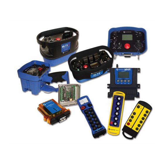
The Radio Control Programmer (RCP) is a user-friendly, Windows based, interactive radio control programmer software. It is designed for communication from your PC to Magnetek radio control products. The USB RCP Kit (Magnetek Part Number 178-01702-0200) contains the following components: 1. -
Page 9: Pc Requirements
PC with 1GHz 32-bit (x86) or 64-bit (x64) processor or better with at least 2GB of RAM and 20 GB hard drive. USB Port, Mouse (or other pointing device), and Keyboard. Internet Connection (for product activation only). RCP User’s Guide July 2017 Page 9 of 110... -
Page 10: Installation
4 Installation Insert the USB flash drive containing RCP into a USB port on your PC. Navigate to the flash drive and locate the RCP_Installer.exe file. Double-clicking this file will start the installation process. When the installation is complete, RCP will be installed on your PC. -
Page 11: Software Removal
4.3 Software Removal To remove the RCP software, open the control panel’s “Programs & Features” dialog box (Windows 7 and 8), double-click the Radio Control Programmer entry, and choose “Remove All” from the dialog box. In Windows 10, select “Settings” from the Start menu, and then “System” > “Apps & features”. Select the Radio Control Programmer entry, and then select “Uninstall.”... -
Page 12: Getting Started
After clicking this, a new dialog will pop up, prompting the user to choose the type of device they would like to add to the project. This lists all of the devices supported by RCP. Select the device type to add to the project. - Page 13 After selecting the device type, the user then has the ability to give the device a name. The device name is solely used within RCP to help denote different devices within a project. Certain devices support the ability to receive the device data upon being added to the project. If a device does not support this, then the option will be greyed out.
-
Page 14: Opening An Existing Project
If you hover over the check box or text a tooltip will appear detailing the data that will be transferred from the device to the RCP project. Clicking “Cancel” will close the pop-up, will not transfer any data, and the project will open with default values. -
Page 15: Recent Project Files
5.2.1 Saving a Project To save a project, click the “File” menu at the top of the RCP screen to open the drop-down menu. The user is then able to select “Save Project” or “Save Project As…” If this is a new project, clicking on “Save Project”... - Page 16 Putting the device in bootloader mode allows firmware to be loaded on the device. Once the device is reset the other buttons will be enabled. The text area will be updated with the status of the reset. RCP User’s Guide July 2017 ...
-
Page 17: Rcp Options
ADDING OR REMOVING A USB DEVICE DURING PROGRAMMING WILL CAUSE THE PROGRAMMING TO FAIL. 5.2.3 RCP Options Figure 2: Select Tools->Options to Launch the RCP Options Dialog RCP logging configuration from the Options dialog. Verbose: Log more data than usually logged. -
Page 18: Open Log File Directory
Select “OK” to apply the log file configuration changes or “Cancel” to exit and undo changes. The log file configuration values are saved to the RCP application settings file upon exiting RCP. The settings are read into RCP when RCP is started so that the configuration values are what they were the last time RCP ran. -
Page 19: Removing Control Characters From The Project File
RCD project file contains control characters. If the project file contains control characters, RCP will display an error when trying to open the project file. If this occurs, run this on the project file to remove the characters, and then reopen the project file; it will then load without error. -
Page 20: Device Programming
NOTE: Reference the specific device manual for details on connecting the USB cable. 2. Click the “Send” button on the RCP screen. A dialog box will pop up confirming that you want to proceed. Check the box marked “I accept,” select the data you wish to send to the device, and then click the button “Continue Send to Radio.”... -
Page 21: Receiving Device Configuration
2. Click “Receive” and follow the on-screen prompts. 3. RCP will confirm reception and automatically display current programming in the unit. Unit Info – This will receive the information located in the “Unit Info” section panel located on the left hand side of the tab page. - Page 22 On-screen prompts will confirm that the receiver has been reset to defaults or will notify you if there are any issues. 4. Power cycle the device to implement the factory default values. RCP User’s Guide July 2017 Page 22 of 110...
-
Page 23: Channel And Frequencies
In doing so, this protocol is able to compensate for interference that may be present on a single frequency by sending the message across multiple frequencies. RCP User’s Guide July 2017 Page 23 of 110... -
Page 24: Devices - Transmitters
Project ID This section displays the project ID for the device. The project ID is set by the factory and cannot be modified by the user. Range: 1-65535 RCP User’s Guide July 2017 Page 24 of 110... - Page 25 If the device supports the feature, then the drop-down box is enabled. Devices with updated firmware to support this feature may not have the option to select the pack type and the RCP control will be read-only. Older firmware will be reported as feature is not supported.
- Page 26 For devices that support the USB communication a new feature has been added in the 2.5 release of RCP. This feature allows the device configuration to be read from and written to the device with the IR adapter (refer to the product-specific manual for the location of the IR window).
-
Page 27: Input Configuration
These procedures can be referenced in the product-specific transmitter manual. Once the device has been placed in this mode RCP can then start to communicate with the device. NOTE: Make sure that the IR adapter and the device’s IR window are lined up. Do not move the IR adapter when communication is occurring as this may cause errors in RCP. -
Page 28: Digitals
Each of the minimized panels can be clicked to expand to display the list of available inputs for the listed transmitter. 7.2.1 Digitals RCP User’s Guide July 2017 Page 28 of 110... -
Page 29: Motions
Priority – The input priority for the display line. For example, if you have configured two inputs to be displayed on the same line, you can configure which input has priority. The input with the RCP User’s Guide July 2017 ... -
Page 30: Analogs
3 “#” and replace it with the 0-100 value read from the analog input on the device. The 0-100 value is a percent of full scale for the input. The ### can be moved around RCP User’s Guide July 2017 ... -
Page 31: Feedback Configuration
7.3 Feedback Configuration The Feedback Configuration feature gives the user the ability to configure the feedback to the display of a transmitter though the RCP user interface. Figure 4. Feedback Configuration Interface RCP User’s Guide July 2017 ... -
Page 32: Formatting Feedback String
54.1 ##.# 89.49 89.5 #### 12345 12345 Table 3. Feedback String Examples NOTE: The underscore (_) in the above display examples is only to show how the value is offset. RCP User’s Guide July 2017 Page 32 of 110... -
Page 33: Examples
Single analog feedback value The user configured the receiver (in RCP) to place an ID value in an RF Command Type of Analog and at Function 1. When the ID value in the RF message is 21 there shall be a message displayed on the screen that reads “MY string.”... - Page 34 7.3.2.5 Feedback with multiple messages configured Figure 5: User Interface Screenshot If There are Several Messages Configured RCP User’s Guide July 2017 Page 34 of 110...
-
Page 35: Devices - Receivers
8 Devices - Receivers 8.1 Unit Info Tab The screenshot below shows the properties for an MHR. Most Magnetek receivers will have similar properties. Device‐level navigation is done using these tabs. Page navigation for each device is done using these tabs. RCP User’s Guide July 2017 Page 35 of 110... - Page 36 Table 4. Unit Info Properties gives a detailed description of each of the properties. NOTE: Changing any of these details will require a reboot of the attached device after the new information has been sent to the device. RCP User’s Guide July 2017 Page 36 of 110...
- Page 37 ESTOP Configuration CAN-2 Only Table 4. Unit Info Properties NOTE: Some versions of RCP will permit the changing of the Project ID field. The factory will determine if a user is eligible for a version with this ability. RCP User’s Guide July 2017 ...
- Page 38 A read-only field that displays the type of expansion board that is connected. Program Loaded A read-only property showing if a user-defined map is loaded in the system. RCP User’s Guide July 2017 Page 38 of 110...
- Page 39 ALWAYS REMEMBER TO STORE THE PASSWORD IN A SECURE LOCATION FOR ACCESS IF THE PASSWORD IS LOST OR FORGOTTEN. ONCE THE DEVICE IS PROGRAMMED WITH A PASSWORD, THERE IS NO WAY TO DEFEAT THE PASSWORD WITHOUT USING THE RCP SOFTWARE TO EITHER READ THE PASSWORD OR REPROGRAM A NEW PASSWORD.
-
Page 40: Device Block Diagram And Pin Properties Grid
In these screenshots the device being programmed is an MHR. For programmable devices the screen will have a similar layout. A selection here… …changes the properties that are displayed in the grid. RCP User’s Guide July 2017 Page 40 of 110... -
Page 41: Can Configuration
CAN bus. This allows the user to modify the CAN bus network communication settings by selecting which CAN bus to configure. Figure 6: CAN 1 Bus Configuration (MHR) RCP User’s Guide July 2017 ... - Page 42 Enable/Disable Status PGN 65411 (Available in CAN-2 only) Enable PGN 65412 Enable/Disable Status PGN 65412 (Available in CAN-2 only) Enable PGN 65413 Enable/Disable Status PGN 65413 (Available in CAN-2 only) RCP User’s Guide July 2017 Page 42 of 110...
-
Page 43: Analog Input Configuration
NOTE: The device must be running a specific version of the hex file for it to accept and run the program created for it. There are special versions of firmware for the receivers that permit RCP-created mappings to be loaded on the product. Refer to Section 5.2.6 for information on where to locate these firmware files. -
Page 44: Programming Tab Layout
Property Grid – This area is populated with a list of properties that are associated with each of the commands, functions, and I/O. Each of the properties in the grid can be selected to view a description of that property. RCP User’s Guide July 2017 ... -
Page 45: Multi-Select
The selection rectangle does not have to encompass the entire channel. RCP User’s Guide July 2017 ... -
Page 46: Right-Click Options
These options change depending on the selection. Figure 10: Single Item Right-click vs. Multi-Item Right-click Delete Selected: Clicking this item in the list removes the channel from the workspace. RCP User’s Guide July 2017 Page 46 of 110... - Page 47 Ctrl+A Vertically align the selected channels in the workspace. Automatically moves any channels that have a negative x-y Ctrl+Shift+A coordinate to zero. This can occur if the channel group is RCP User’s Guide July 2017 Page 47 of 110...
-
Page 48: Programming Tab Button Functions
Figure 15: RF Message Channels 8.2.6 Receiver User Interface There will be a new channel added to RCP and supporting device firmware to support feedback. This channel will allow data to be sent back to the transmitter. RCP User’s Guide July 2017 ... - Page 49 The user can select type as Digital/Analog and the Function to store the data in the message. Refer to Section 7.3 for details on configuring transmitter feedback. The feedback channel supports 16bits of data. RCP User’s Guide July 2017 Page 49 of 110...
- Page 50 When the library group is placed in the workspace the group is selected so it can be easily dragged to a new location. All library groups are added to the workspace in the same location, so they must be moved or they will overlap other channels in the workspace. RCP User’s Guide July 2017 ...
- Page 51 Figure 20: PGN In -> 8 Bytes Command Figure 21: 8 Bytes => PGN Out Command Figure 22: RFCmd Digital In => 8 Bits Command RCP User’s Guide July 2017 Page 51 of 110...
- Page 52 Figure 23: RFCmd => Matrix => Relays Figure 24: 16-Bit CAN Data Used as Feedback Figure 25: 1Bit of Feedback Data RCP User’s Guide July 2017 Page 52 of 110...
-
Page 53: Device Mapping
Depending on the device the number and type of inputs and outputs will vary. 9.1.1 Channel Image Field Description This field displays the type This field contains the name of channel. of the channel. The user can modify this field through the property grid. This field is specific to an This field displays the unique ID of I/O type channel showing the channel. This field helps identify how the I/O is configured. the channel when selecting it with the drop‐downs when connecting them. RCP User’s Guide July 2017 Page 53 of 110... -
Page 54: Connection Limits
Figure 27: Workspace View of Math Operation Figure 28: Equation Shown in Notes Field 9.1.3 Channel Limits Table 9 lists the maximum number of channels that can be programmed via RCP per device. RCP User’s Guide July 2017 ... -
Page 55: Channel Connection Description
The following describes all of the available channel types. For each type there is a description of what the channel is, the channel size (the bit size of the channel), what types of channel inputs can be mapped to the channel, and the devices on which this channel type is supported. RCP User’s Guide July 2017 ... - Page 56 This is typically used to convert analog RF command values from a proportional transmitter into values that make it look like a transmitter sending discrete step values. Value Size: 8 bit Supported Input Connection Types: Math, Constant, RFIn, RF Dig In Supported Devices: inteleSmart2 RCP User’s Guide July 2017 Page 56 of 110...
- Page 57 Value Size: 1-8 bits (configured through property) Supported Input Connection Types: IO (Input), Math, CAN (Parameter In), Constant, RF Command, RF Command Digital Byte Bits (In), Scaling Supported Devices: MHR, MHC, inteleSmart2, CAN-2 RCP User’s Guide July 2017 Page 57 of 110...
- Page 58 Value Size: Varies depending upon the configuration (16 bit max) Supported Input Connection Types: IO (Input), Math, CAN (Parameter In), Constant, RF Command, RF Command Digital Byte Bits (In), Scaling Supported Devices: MHR, MHC, inteleSmart2, CAN-2 RCP User’s Guide July 2017 Page 58 of 110...
-
Page 59: Transmitter Component To Rf Message Mapping
NOTE: Similar connections are laid out the same for each of the connection types. Connection Definition Source voltage P_COM Ground Dir# (1/2) Digital connection that determines the direction of the paddle Motion# Analog input Analog# Analog input RCP User’s Guide July 2017 Page 59 of 110... - Page 60 To map a paddle’s forward and reverse motion when the paddle is plugged into the Motion 1 connection, two channels are required in RCP to handle the forward and the reverse motions. To determine how the channels are configured, refer to the tables in Section 9.2.4 to determine the Command Function values.
- Page 61 Figure 31: CHTX and MLTX2 Motion and Analog Connections (Side 2) Figure 32: XLTX Connections (Side 1) When connecting a dial to the POT1 connection on an XLTX, the RF command channel in RCP would be configured as Analog and the Function property would be Function 1.
- Page 62 Figure 35: MBT/PGT Toggle Board (Side 1) NOTE: Similar connections are laid out the same for each of the connection types. The orientation is the same for each of the six- hole connector pads. RCP User’s Guide July 2017 ...
- Page 63 NOTE: Similar connections are laid out the same for each of the connection types. The orientation is the same for each of the three-hole connector pads. Figure 37: MBT/PGT Generic I/O Board (Side 1) RCP User’s Guide July 2017 Page 63 of 110...
- Page 64 Figure 38: MBT/PGT Generic I/O Board (Side 2) Figure 39: Mini-PGT/MBT Connections For the Mini-PGT/MBT connectors above, refer to the following table mappings for the connection information. RCP User’s Guide July 2017 Page 64 of 110...
-
Page 65: Transmitter Button Layout - Flex Vue
9.2.2 Transmitter Button Layout – Flex VUE Figure 40: Flex VUE Table 12 shows how the buttons from the transmitter shown in Figure 40 map to the RCP RF Command and Function. The first column shows the button number based upon the figure. The second column RCP User’s Guide... -
Page 66: Transmitter Button Layout - Telependant/Telepilot
Figure 41: telePilot, 2-Speed and Single-Speed Transmitters Table 13 shows how the buttons from the TX12M-1 shown in Figure 41 map to the RCP RF Command and Function. The first column shows the button number based upon the figure. The second column shows the RF Command, Function, and bit that need to be chosen to access the button command via the RF message. - Page 67 Table 14 shows how the buttons from the TX12M-2R shown in Figure 41 and the transmitter in Figure 42 map to the RCP RF Command and Ffunction. The first column shows the button number based upon the figure. The second column shows the RF Command, Function, and bit (if applicable) that need to be chosen to access the button command via the RF message.
- Page 68 Motor 2 Select B Digital/Function 7/bit 4 Motor 3 Select A Digital/Function 7/bit 5 Motor 3 Select B Digital/Function 7/bit 6 Table 14. telePilot/telePendant 2- and 3-Speed Transmitter Button Mapping RCP User’s Guide July 2017 Page 68 of 110...
-
Page 69: Transmitter Radio Message Mapping
Function 12 8 bits P6 (MTN6 Dir2) P6 (MTN6 Dir2) Button12 Button12 Button12 Button12 Motion Function 13 8 bits P7 (MTN7 Dir1) P7 (MTN7 Dir1) Motion Function 14 8 bits P7 (MTN7 Dir2) P7 (MTN7 Dir2) Motion Function 15 8 bits P8 (MTN8 Dir1) Motion Function 16 8 bits P8 (MTN8 Dir2) Table 15. Motion Commands RCP User’s Guide July 2017 Page 69 of 110... - Page 70 Bit 2 1 bit P9‐3 (Rotary 2) P9‐3 (Rotary 2) Bit 3 1 bit P9‐4 (Rotary 3) P9‐4 (Rotary 3) Bit 4 1 bit P9‐5 (Rotary 4) P9‐5 (Rotary 4) Digital Function 8 Bit 5 1 bit P9‐6 (Rotary 5) P9‐6 (Rotary 5) Bit 6 1 bit P9‐7 (Rotary 6) P9‐7 (Rotary 6) Bit 7 1 bit Bit 8 1 bit Table 16. Digital Commands RCP User’s Guide July 2017 Page 70 of 110...
- Page 71 Function 11 8 bits P16‐4 (AN11) P16‐4 (AN11) Analog Function 12 8 bits P16‐5 (AN12) P16‐5 (AN12) Analog Function 13 8 bits P16‐6 (AN13) P16‐6 (AN13) Analog Function 14 8 bits Analog Function 15 8 bits Analog Function 16 8 bits Table 17. Analog Commands RCP User’s Guide July 2017 Page 71 of 110...
-
Page 72: Examples
A mapping of this nature will be uncommon, but this is intended to show the basics of how programming a device is accomplished. Further sections will get into more detail with additional mapping options and features. Click to add I/O to workspace. I/O added to workspace. RCP User’s Guide July 2017 Page 72 of 110... - Page 73 Click and drag channel to new location in workspace. When the project was created, the option to read device data was checked, so the device configuration will be used when a selection is made. RCP User’s Guide July 2017 Page 73 of 110...
- Page 74 Click in the textbox and enter the I/O number. The channel will change to match the configuration of the device. RCP User’s Guide July 2017 Page 74 of 110...
- Page 75 Drag the new channel near the Output #9 channel. Select the I/O number that matches the configuration you are creating. The next screenshot will show these step already completed. RCP User’s Guide July 2017 Page 75 of 110...
- Page 76 Map the input channel to an output channel. Click the channel to display properties. Click on the “Input Control” property. This displays a list of available channels to use as input. RCP User’s Guide July 2017 Page 76 of 110...
- Page 77 Once the selection is made… … A connection will appear between the channels. Now the configuration is ready to compile and load onto the device. RCP User’s Guide July 2017 Page 77 of 110...
- Page 78 Click “Compile” to check for errors. RCP User’s Guide July 2017 Page 78 of 110...
- Page 79 The “Compile” button runs a series of checks on the mapping that was created prior to allowing the configuration to be loaded onto the device. Now the program is ready to send and load onto the device. RCP User’s Guide July 2017 Page 79 of 110...
- Page 80 Click “Send Program” to load the program on to the device. RCP User’s Guide July 2017 Page 80 of 110...
- Page 81 Click “Close” to continue. At this point the mapping has been loaded onto the device, and it should be running the loaded mapping. RCP User’s Guide July 2017 Page 81 of 110...
-
Page 82: Mapping An Incoming Rf Message
Start by creating a new project with an MHR device selected and allow the device configuration to be read. This is the same process explained in Section 5. Once the project is started, navigate to the Programming tab across the bottom of the UI. RCP User’s Guide July 2017 ... -
Page 83: Rcp User's Guide July
Select the RF Command tab. RCP User’s Guide July 2017 Page 83 of 110... - Page 84 Click “RF Cmd In” to add the channel to the workspace. RCP User’s Guide July 2017 Page 84 of 110...
- Page 85 Now the incoming message command should be selected. Based on Table 16 in Section 9.2.4, button 1 of the Flex VUE maps to a Motion command with Function 1. That information allows the user to configure the channel accordingly. RCP User’s Guide July 2017 ...
- Page 86 Select the corresponding Function number from the list. RCP User’s Guide July 2017 Page 86 of 110...
- Page 87 After selecting the Function number from the list, the channel will reflect the selection. Now the data from this command can be used to drive another channel. RCP User’s Guide July 2017 Page 87 of 110...
-
Page 88: Using The Matrix Channel To Configure Relays
Start by creating a new project with an inteleSmart2 device selected and allow the device configuration to be read. Follow the steps as detailed out in Section 5 to get started. Once the project is started, navigate to the Programming tab at the bottom of the UI. RCP User’s Guide July 2017 ... - Page 89 Click “Matrix” to add the channel to the workspace. The “Matrix” is added to the workspace. RCP User’s Guide July 2017 Page 89 of 110...
- Page 90 Number of Speeds: Controls the number of columns displayed. Number of Relays: Controls the number of rows displayed. Input Mode: Controls how the relays are driven. The Input Mode property controls the number of Speed Input properties available to edit. RCP User’s Guide July 2017 Page 90 of 110...
- Page 91 Input Label properties allow the user to change the text corresponding with the inputs. Relay Labels property allows the user to change the text on the channel. Click “Relay” to add a Relay Channel to the workspace. RCP User’s Guide July 2017 Page 91 of 110...
- Page 92 Select a relay to map the channel to. This list is comprised of main board. Choose the state of the Relay (Normally Open or Normally Closed). RCP User’s Guide July 2017 Page 92 of 110...
- Page 93 Select Input, then select the connection point of the Matrix Channel that you want the relay to connect to. The connection is made once the connection point is selected. Click to add analog to discrete channel to workspace. RCP User’s Guide July 2017 Page 93 of 110...
- Page 94 From the property grid of the Matrix Channel select the conversion channel as the input for direction 1. Select the Input to the channel. Auto Speed Mode: Adds an additional speed/step to a transmitter that has a fixed number of speeds. Auto Speed Time: The amount of time the transmitter’s max speed is transmitted before increasing to the auto mode speed. The user can select the number of speed points the analog is broken into. This is the maximum number of speed points the Matrix Channel sees unless the auto mode feature is enabled. These are configurable points at which the speed point is generated. There is a 2% hysteresis built into each of the speed points. RCP User’s Guide July 2017 Page 94 of 110...
- Page 95 Click “RF Cmd In” to add an RF Channel to the workspace. Configure the channel using the RF messaging table. Map the input of the analog conversion channel to the RF Cmd In. RCP User’s Guide July 2017 Page 95 of 110...
-
Page 96: Multi-Input Mode Using The Matrix Channel
This is the same process explained in Section 5. Once the project is started, navigate to the Programming tab across the bottom of the UI. From the I/O tab add a Matrix Channel to the workspace. Changing the Input Mode of the channel changes the Matrix Channel display. This mode allows individual channels to drive each of the speed points defined. Changing the Input Mode enables the corresponding input properties. The number of enabled inputs is based on the number of speed points selected. RCP User’s Guide July 2017 Page 96 of 110... - Page 97 The input channel mapped to the input for Multi‐Input Mode is configured using the drop‐ down options. NOTE: Any values greater than zero will cause the relays mapped to the input to be driven high. RCP User’s Guide July 2017 Page 97 of 110...
-
Page 98: Intelesmart2 Pre-Defined Crane Configuration
9.3.5 inteleSmart2 Pre-defined Crane Configuration Click button to load the Crane Configuration properties. RCP User’s Guide July 2017 Page 98 of 110... - Page 99 Used when operating the receiver with a five-speed belly box transmitter. 10K pendant option MUST be checked when using bypass. RCP User’s Guide July 2017 Page 99 of 110...
- Page 100 WARNING IF YOU NEED TO ADD GROUP CODE OR ADD ADDITIONAL TRANSMITTERS PLEASE CONTACT MAGNETEK FOR ASSISSTANCE WITH THIS FEATURE. FAILURE TO FOLLOW THIS WARNING COULD RESULT IN SERIOUS INJURY OR DEATH AND DAMAGE TO EQUIPMENT.
- Page 101 ESTOP is used, due to the additional frequency/channel loading. Check the active ESTOP box if this feature is desired. Click this button to generate a mapping. A mapping will be available on the Programming page based on the Pre‐Configured crane type selected. Figure 43: Generating Pre-configured Mapping RCP User’s Guide July 2017 Page 101 of 110...
-
Page 102: Mapping
9.3.6 CAN-2 Mapping The CAN-2 device is configured the same as the MHR and inteleSmart2 devices. The CAN-2 also requires special firmware to support the mapping capability of RCP. 9.3.7 Additional Mapping Examples This section shows some commonly used mappings. Refer to Section 1.1 for specifics on each of the various types of connections. - Page 103 Figure 48: Data from the RF Command Distributed through Several Channels Figure 49: Scale an 8-Bit RF Message to a 10-Bit Value to Drive an Output NOTE: This is needed to achieve full scale on the output. RCP User’s Guide July 2017 Page 103 of 110...
-
Page 104: Rf Masking
The following diagram shows how to drive a digital and an analog type output using the dead-band channel. This approach allows the processing to occur prior to output and can be applied to more output types. RCP User’s Guide July 2017 ... -
Page 105: Timer Channel
Trigger Based: When the timer operates in this mode there are properties that allow the user to select what triggers the timer to start and what triggers the timer to stop. Figure 55: Trigger Timer Example RCP User’s Guide July 2017 Page 105 of 110... - Page 106 Select a channel to start the timer. A value greater than zero will cause trigger. Reset Trigger Select a Channel Select a channel to stop/reset the timer. A value greater than zero will cause trigger. RCP User’s Guide July 2017 Page 106 of 110...
- Page 107 Phase A Time Phase B Time Phase A Time Phase B Time 100ms 200ms 300ms 400ms 500ms 600ms 700ms 800ms 900ms 1000ms Phase A State Reset State Phase B State Phase B State Reset State Phase A State Phase A State Start Trigger Reset Trigger Figure 58: Trigger-Based Timing Diagram RCP User’s Guide July 2017 Page 107 of 110...
-
Page 108: Rf Output Channel (Feedback Channel)
9.3.11 RF Output Channel (Feedback Channel) The diagram below shows how to send feedback to the transmitter. The example shows incoming CAN data being sent as a 16‐bit data message and a 1‐bit message being sent. There can be multiple 1‐bit channels attached to the RF Out Channel. RCP User’s Guide July 2017 Page 108 of 110... - Page 109 16‐bit RF Out (Feedback) message properties. The Only every other “Function” is available. This is RF Command property is set to Motion because a “Function” represents an 8‐bit index to where the data is stored in the packet being sent to the receiver. Therefore, sending 16 bits of data will consume two Function indexers for every 16 bits of data. Digital feedback Function selection has all 16 Functions available for selection. RCP User’s Guide July 2017 Page 109 of 110...
-
Page 110: July 2017
Single Channel (Feedback) message properties. Multiple single bits packed into the digital The RF Command property is set to Motion. feedback message. RCP User’s Guide July 2017 Page 110 of 110...
Need help?
Do you have a question about the RCP and is the answer not in the manual?
Questions and answers