Table of Contents
Advertisement
INSTALLATION AND OPERATING INSTRUCTIONS
CYCLING DC MOTOR CONTROL
– Designed for Indexing Applications –
This manual covers the following CAMCO part numbers:
92A61633010000, 92A61633020000, 92A61633030000, 92A61633040000
See Safety Warning on Page 2
The information contained in this manual is intended to be accurate. However, the manufacturer
retains the right to make changes in design which may not be included herein.
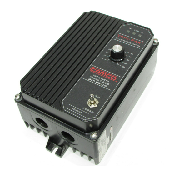
VARI-PAK
Industrial Motion Control, LLC
ON
STOP
OL
VARI-PAK
DC MOTOR SPEED CONTROL
50
40
60
30
70
20
80
10
90
0
100
%
144 S. Wolf Rd
Wheeling, IL 60090
(847) 459-5200
RUN
JOG / STOP
NEMA-12
© 2003 KB Electronics, Inc.
Advertisement
Table of Contents

Summary of Contents for Camco VARI-PAK
- Page 1 Wheeling, IL 60090 (847) 459-5200 JOG / STOP NEMA-12 This manual covers the following CAMCO part numbers: 92A61633010000, 92A61633020000, 92A61633030000, 92A61633040000 See Safety Warning on Page 2 The information contained in this manual is intended to be accurate. However, the manufacturer retains the right to make changes in design which may not be included herein.
-
Page 2: Table Of Contents
TABLE OF CONTENTS Section Page Simplified Operating Instructions ......... . 1 Safety Warning . -
Page 3: Simplified Operating Instructions
SIMPLIFIED OPERATING INSTRUCTIONS IMPORTANT – You must read these simplified operating instructions before pro- ceeding. These instructions are to be used as a reference only and are not intended to replace the detailed instructions provided herein. You must read the Safety Warning, on page 2, before proceeding. -
Page 4: Safety Warning
Contact factory for detailed installation and Declaration of Conformity. Installation of a CE approved RFI filter (KBRF-200A [P/N 9945C] or equivalent) is required. Additional shield- ed motor cable and/or AC line cables may be required along with a signal isolator (Camco P/N 99A61455000000). -
Page 6: General Performance Specifications
TABLE 2 – GENERAL PERFORMANCE SPECIFICATIONS Specifications Specifications Part Nos. Part Nos. Parameter Factory Factory (Units) 92A61633010000 92A61633030000 Setting Setting 92A61633020000 92A61633040000 AC Line Input — 208/230 — (VAC ± 10%, 50/60 Hz) Horsepower Range HP, (kW) 1/6 – 1, (0.12 – 0.75) 1/3, (0.25) 1/3 –... -
Page 7: Control Layout (Non-Reversing Units)
FIGURE 2A – CONTROL LAYOUT (Non-Reversing Units) (92A61633010000 and 92A61633030000) (Illustrates Factory Setting of Jumpers and Approximate Trimpot Settings) CON1 CON2 RUN FWD JOG FWD STOP +24V 90V 180V 240V 120V J2B J2A... -
Page 8: Control Layout (Reversing Units)
FIGURE 2B – CONTROL LAYOUT (Reversing Units) (92A61633020000 and 92A61633040000) (Illustrates Factory Setting of Jumpers and Approximate Trimpot Settings) CON1 CON2 RUN REV JOG REV RUN FWD JOG FWD STOP +24V 180V 240V 120V J2B J2A... -
Page 9: Mechanical Specifications
FIGURE 3 – MECHANICAL SPECIFICATIONS (Inches / [mm]) -
Page 10: Mounting
TABLE 3 – SELECTABLE JUMPER REFERENCE CHART Jumper Location* Description Factory Setting Establishes the range of maximum armature current See section III, page 8 Sets the AC input line voltage (120 or 240 Volts AC) for Set according to model part J2A, J2B the main PC Board numbers. -
Page 11: Terminal Block Wiring Information
Failure to follow the Safety Warning Instructions may result in electric shock, fire or explosion. Do not fuse neutral or grounded conductors. Note: See section V, Fusing, on page 10. A separate AC line switch, or contactor, must be wired as a disconnect switch, so that the contacts open each ungrounded conductor. -
Page 12: Fusing
Note: If an isolated signal voltage is not available, an optional signal isolator (Camco P/N 99A61455000000) should be used. FIGURE 6 – ANALOG VOLTAGE Connect the isolated input voltage to CONNECTION terminal P2 (positive) and P1 (negative). -
Page 13: Jog Command
FIGURE 8 – JOG COMMAND B. ”JOG” (Stop) – A maintained contact closure between terminals “JOG” and “RTN” will cause the control to run RTN +24V COM continuously. This is not a latching function. The drive will run only as long as the contact is closed and stop when it is opened. -
Page 14: Vii. Application Wiring Diagrams
TABLE 6 – JUMPER “JW” OPERATION Jumper “JW” Setting Description Circuit Operation “Run” has priority When start contact is over “Stop.” Control made, control will run will run even if stop with stop open. If contact is open. Use stop is closed and this setting for “Cycle then reopened, con- on Demand”... -
Page 15: Solid State Switching
Stopping in any other position could damage the control or the Index Drive! Read all the instructions carefully in order to familiarize yourself with your new CAMCO Index Drive. (See figures 14A, 14B and 14C.) FIGURE 14 – CORRECT KEYWAY POSITION FOR CAM & LIMIT SWITCH ASSEMBLIES FIGURE 14A –... -
Page 16: Cycle On Demand Wiring
FIGURE 14B – RIGHT ANGLE UNIT FIGURE 14C – PARALLEL UNIT Keyway Keyway A standard parallel unit with the CAM & Limit Switch mounted on the housing has a correct keyway position directly opposite of the output A standard right angle unit with the CAM & shaft, 90º... -
Page 17: Application Wiring Diagrams (Reversible Models)
FIGURE 16 – SEQUENCE OF CYCLE ON DEMAND OPERATION CONTACT IS OPENING CONTACT CLOSES ROTATION OF CAM 1) CLOSE START BUTTON TO INITIATE CYCLE (MOMENTARY CLOSURE) 2) CAM ROTATES, LS1 CONTACT CLOSES CONTACT OPENS CONTACT REMAINS CLOSED 4) CAM ROTATES UNTIL LOBE UNTIL LS1 CONTACT, 1) CAM CONTINUES TO ROTATE THROUGH DRIVE BRAKES TO A STOP. -
Page 18: Trimpot Adjustments
FIGURE 17 – REVERSING LOGIC WIRING DIAGRAMS FIGURE 17A – GENERAL FIGURE 17B – REVERSING CONNECTION DIAGRAM USING EXTERNAL CONTACTS RUN REV RUN REV JOG REV JOG REV RUN FWD RUN FWD JOG FWD JOG FWD STOP STOP USE NORMALLY OPEN +24V MAINTAINED CONTACTS FIGURE 17C –... -
Page 19: Function Indicator Lamps
WARNING! Do not adjust trimpots with main power on if possible. If adjust- ments are made with power on, insulated adjustment tools must be used and safety glasses must be worn. High voltage exists in this control. Electrocution and/or fire can result if caution is not exercised. Safety Warning on page 2 must be read and understood before proceeding. - Page 20 C. Overload Indicator (OL) – When the motor is loaded to the current limit setpoint (CL set- point is established by the setting of jumper J1 and the CL trimpot) this lamp will glow RED. If the OL indicator remains lighted during control operation, a fault condition may exist.
-
Page 21: Troubleshooting Guide
XII – TROUBLESHOOTING GUIDE MOTOR WILL NOT RUN: 1. Check control operation by placing RUN - JOG/STOP in RUN position. 2. Make sure disconnect fuses or circuit breaker in AC line are okay. 3. Check fuse on PC board, and if open, replace. 4. -
Page 22: Internal Wiring Diagram
FIGURE 18 – INTERNAL WIRING DIAGRAM... - Page 23 – NOTES –...
- Page 24 INDUSTRIAL MOTION CONTROL, LLC 1444 SOUTH WOLF ROAD WHEELING, IL 60090 USA Tel: 847-459-5200 Toll-Free: 800, 645-5207 (A40290) – Rev. H – 7/2003...
Need help?
Do you have a question about the VARI-PAK and is the answer not in the manual?
Questions and answers