
Related Manuals for Magnescale MG80-PN


Summary of Contents for Magnescale MG80-PN
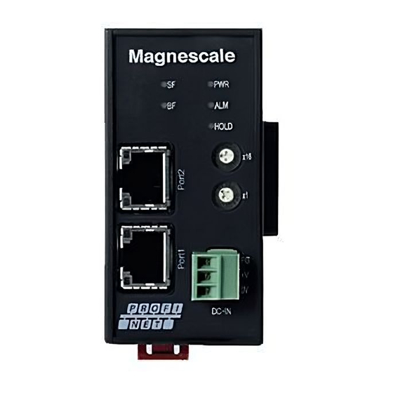
- Page 1 PROFINET Interface Module MG80-PN Read all the instructions in the manual carefully before use and strictly follow them. Keep the manual for future references. Operating Manual...
-
Page 2: Table Of Contents
3.2. About IO data ......................5 3.3. Setting various parameters ..................5 3.3.1. Connection ......................6 3.3.2. Setting method ......................7 3.3.3. Restart MG80-PN ....................13 4. Specifications ........................14 4.1. Interface specifications .................... 14 4.2. LED indicator ......................15 5. -
Page 3: Revision History
Revision history Revision Date Description Pages 1.00 2020/07/27 1.01 2020/10/28 Corrections of errors and additions... -
Page 4: Introduction
This manual describes the details of the functions and the communication setting method. For MG80-PN, MG80-CM and LZ80, refer to the attached instruction manual of each device. For basic information of PROFINET, refer to the manual of each PLC manufacturer. -
Page 5: Basic Information
・Up to 16 counter module MG80-CM can be connected to one MG80-PN. ・Connect the measuring unit DK series to MG80-CM. ・Measuring unit numbers are automatically assigned in order from 1 closest to MG80-PN. ・For PROFINET or Ethernet connection, prepare a shielded cable with RJ45(8P8C) connector. -
Page 6: Setting
When the GSDML file is imported into the development environment, the IO data is handled as Byte array data. Please refer to “6. Communication” page of the text for IO data mapping. 3.3. Setting various parameters Various settings of MG80-PN can be performed from PC by using “Setting application for Windows PC”... -
Page 7: Connection
Subnet mask :255.255.255.0 ※1 Address that cannot be set to XXX - “1” that is used when setting with the MG80-PN. - Same address as other connected devices. 3. Set the setting switch to “0x00” to enter the setting mode and enable communication with the computer. -
Page 8: Setting Method
3.3.2. Setting method Set various operation parameters using the “Setting application for Windows PC”. “ MG80ModuleSettingTool.” installed on the PC is started, the following screen appears. Network settings (do not use) Connection Parameter settings... - Page 9 2. Click the Connect button at the top right of the setting application. 3. If the connection is successful, the network setting field and parameter setting field become valid. If the connection fails, turn off the power of the MG80-PN and start again from the setting application.
- Page 10 After setting the parameters on each parameter screen, click the “Set” button at the bottom of the screen to send and save the parameters to MG80-PN Note) If you do not click the “Set” button, it will not be saved in MG80-PN, so be sure to execute it on each screen.
- Page 11 Setting items Setting item Contents (Parameter name) Setting of input resolution, direction, reference point, and master preset value Axis for each axis. (Axis Setting) Frame Addition and subtraction function, output type, preset value setting for each (Frame Setting) frame Comp Comparator threshold setting, number of step mode, setting of comparator (Comparator Setting) use group number for each frame.
- Page 12 (1) Axis Setting screen Reference point preset value (Unit: 0.1μm) Select from the pull-down Axis number Input resolution:(0.1, 0.5, 1.0, 2.0, 5.0, 10.0μm) Direction: Count direction of measuring unit Use Ref point: Valid or invalid of reference point (2) Frame Setting screen Preset value (Unit: 0.1μm) Frame number Select from the pull-down...
- Page 13 (3) Comparator Setting screen Select the group Step setting number to be set in the Select the frame to set selected frame. (2step/4step) Group number of Comparator setting comparator settings Click up or down or enter key figures. (Unit: 0.1μm) (4) I/O Setting screen Input/output setting of the Input/output setting of the...
-
Page 14: Restart Mg80-Pn
1. After setting and saving all parameters, turn off the power. 2. The IP address used in the actual measurement is set from the PLC, so set a value other than 0x00 with the setting switch on the MG80-PN. 3. Restart the power to operate with the set parameters. -
Page 15: Specifications
In “Setting mode”, it can be set the operation parameters using the setting application for Windows PC. Power FG ×1 Terminal ×1 All modules and measuring units connected to MG80-PN are supplied +V ×1 (3 pole) from this power supply terminal. 0V ×1... -
Page 16: Led Indicator
4.2. LED indicator The definition of LED display is described below. [PWR] Power LED :Displays the operation status of this module Color Status Contents Green Turns off Power off Lights up Ready for operation after power on [ALM] Alarm LED :Displays the alarm status of all modules. Color Status Contents... - Page 17 Communication port status confirmation LED Displays the link status of communication port 2 Color Status Description Green Turns off Link not established Lights up Link established Displays the link speed of communication port 2 Color Status Description Orange Turns off Abnormal communication speed Lights up Communication speed is normal...
-
Page 18: Function
5.1. Functions list Item Contents Condition Module configuration MG80-PN can be expanded to 255 units via PROFINET network (total 4080axes) Whole system Number of Counter module MG80-CM:From 1 to 16units (Measuring unit 1 to 16 axes) connectable modules I/O module LZ80-K1/K2:Max. 2units... -
Page 19: Frame Definition
Up to 16 frames can be set for each unit (maximum connection configuration: MG80-PN x1, MG80-CM x 16, LZ80-K1/K2 x2). Each of the 16 frames is called a frame number from A to P. Each frame can be read as RT communication of PROFINET. -
Page 20: Detail Of Function
5.3. Detail of function 5.3.1. Peak hold The peak value (maximum value, minimum value, peak to peak value) of each frame is always retained. An example of calculating the peak value is shown below. When the measuring unit moves from left to right as shown below, the black line is the current value, red line is max. -
Page 21: Pause
5.3.2. Pause This function holds the current value of the specified frame and the comparator output and peak value for the current value. The transition of the peak value in the pause On / Off state is as shown below. 最大値... -
Page 22: Comparator
5.3.7. Comparator Up to 8 thresholds can be set for 2 or 4(2 steps / 4 steps) for each set frame. Outputs the judgment value for each set area. The set can be specified by the comparator group number setting command. The following is an example of comparator judgment when setting the number of steps. -
Page 23: I/O Module Control
5.3.9. I/O module control Functions can be assigned to the input and output terminals of the connected I/O module. According to the signal status of the assigned input terminal, the operation status such as the comparator judgment of the main module can be changed, and the signal output of the output terminal can be controlled. -
Page 24: Communication
6. Communication Communication with PROFINET device 6.1. controller) MG80-PN supports PROFINET standard communication, and has the following RT communication (real time) and NRT communication (Non Real-time) service functions. 6.1.1. RT communication( Real-time communication) MG80-PN supports RT communication of PROFINET standard and performs Real-time communication with the IO controller (PROFINET master PLC). - Page 25 BOOL IF1.ST6.BW_QuitChannel_A BOOL IF1.ST6.BW_QuitChannel_B BOOL IF1.ST6.BW_QuitChannel_R 3~7 - - BOOL IF1.ST6.Encoder01Reset 1~7 - - BOOL IF1.ST7.BW_QuitChannel_A BOOL IF1.ST7.BW_QuitChannel_B BOOL IF1.ST7.BW_QuitChannel_R 3~7 - - BOOL IF1.ST7.Encoder01Reset 1~7 - - BOOL IF1.ST8.BW_QuitChannel_A BOOL IF1.ST8.BW_QuitChannel_B BOOL IF1.ST8.BW_QuitChannel_R 3~7 - - BOOL IF1.ST8.Encoder01Reset 1~7 -...
- Page 26 BOOL IF1.ST12.Encoder01Reset 1~7 - - BOOL IF1.ST13.BW_QuitChannel_A BOOL IF1.ST13.BW_QuitChannel_B BOOL IF1.ST13.BW_QuitChannel_R 3~7 - - BOOL IF1.ST13.Encoder01Reset 1~7 - - BOOL IF1.ST14.BW_QuitChannel_A BOOL IF1.ST14.BW_QuitChannel_B BOOL IF1.ST14.BW_QuitChannel_R 3~7 - - BOOL IF1.ST14.Encoder01Reset 1~7 - - BOOL IF1.ST15.BW_QuitChannel_A BOOL IF1.ST15.BW_QuitChannel_B BOOL IF1.ST15.BW_QuitChannel_R 3~7 -...
- Page 27 0~7 DINT IF1.ST16.Encoder01 Frame O measured value 60~63 0~7 DINT IF1.ST17.Encoder01 Frame P measured value BOOL IF1.ST1.StatusInput01 MG70-PN used it, but the MG80-PN outputs zero because it is not used. BOOL IF1.ST1.StatusInput02 2~7 - - 0~7 SINT IF1.ST1.SupplyCurrent 0~7 SINT IF1.ST1.SupplyVoltage...
- Page 28 B signal of axis 2 BOOL IF1.ST3.BW_Channel_R Z signal of axis 2 3~7 - - Unused Outputs zero 0~3 - - MG70-PN used it, but the MG80-PN outputs zero because it is not used. BOOL IF1.ST3.DigitalInput01 BOOL IF1.ST3.DigitalInput02 6~7 - - BOOL IF1.ST4.PowerSupply01 MG70-PN used it, but the MG80-PN outputs zero because it is not used.
- Page 29 MG70-PN used it, but the MG80-PN BOOL IF1.ST7.PowerSupply01 outputs zero because it is not used. BOOL IF1.ST7.PowerSupply02 2~7 - - BOOL IF1.ST7.BW_Channel_A A signal of axis 6 BOOL IF1.ST7.BW_Channel_B B signal of axis 6 BOOL IF1.ST7.BW_Channel_R Z signal of axis 6 3~7...
- Page 30 MG70-PN used it, but the MG80-PN 0~3 - - outputs zero because it is not used. BOOL IF1.ST10.DigitalInput01 BOOL IF1.ST10.DigitalInput02 6~7 - - BOOL IF1.ST11.PowerSupply01 MG70-PN used it, but the MG80-PN outputs zero because it is not used. BOOL IF1.ST11.PowerSupply02 2~7...
- Page 31 B signal of axis 13 BOOL IF1.ST14.BW_Channel_R Z signal of axis 13 3~7 - - Unused Outputs zero 0~3 - - MG70-PN used it, but the MG80-PN outputs zero because it is not used. BOOL IF1.ST14.DigitalInput01 BOOL IF1.ST14.DigitalInput02 6~7 - - BOOL IF1.ST15.PowerSupply01 MG70-PN used it, but the MG80-PN outputs zero because it is not used.
- Page 32 0~7 - - Unused Outputs zero 0~7 SINT IF1.ST1.ModuleOk MG70-PN used it, but the MG80-PN outputs zero because it is not used. 0~7 SINT IF1.ST2.ModuleOk Status of MG80-CM 1 0~7 SINT IF1.ST3.ModuleOk Status of MG80-CM 2 0~7 SINT IF1.ST4.ModuleOk Status of MG80-CM 3 0~7...
- Page 33 0~7 SINT IF1.ST9.OutKind Frame H output type 0~7 SINT IF1.ST9.CompKumiNum Frame H comparator group number 0~7 SINT IF1.ST10.CompResult Frame I comparator result 0~7 SINT IF1.ST10.OutKind Frame I output type 0~7 SINT IF1.ST10.CompKumiNum Frame I comparator group number 0~7 SINT IF1.ST11.CompResult Frame J comparator result 0~7 SINT...
-
Page 34: Nrt Communication (Non Real-Time Communication)
6.1.2. NRT communication (Non Real-time communication) MG80-PN can perform NRT command communication (Non Real-time communication) with a master (PLC of PROFINET device) at any timing. Commands such as measurement parameter change and reset are performed by NRT command communication. The data structure of the send command is shown below. -
Page 35: Nrt Communication Command List
6.1.3. NRT communication command list The following is a NRT communication command list. NRT communication command list Command Command Overview number 4(0x04) [Axis number]、[Sign]、[Input resolution setting value] Input resolution setting 5(0x05) Input resolution acquisition [Axis number] 6(0x06) Reference point use setting [Axis number]、[Reference point use setting] 7(0x07) Reference point use setting acquisition... - Page 36 The following shows the details of the NRT communication command. (1) Input resolution setting command Offset Label Setting value (Hex) Please enter an arbitrary value different from the value previously sent. 0x04 RSV1 0x00 RSV2 0x00 DATA1 ※ASCII code Axis number Setting value (Hex) ‘1’~’10’...
- Page 37 (2) Input resolution acquisition command Offset Label Setting value (Hex) Please enter an arbitrary value different from the value previously sent. 0x05 RSV1 0x00 RSV2 0x00 DATA1 ※ASCII code Axis number Setting value (Hex) ‘1’~’10’ 0x30~0x39 ‘11’~’16’ 0x41~0x46 5~15 DATA2 Dummy ~...
- Page 38 (4) Reference point use acquisition command Offset Label Setting value (Hex) Please enter an arbitrary value different from the value previously sent. 0x07 RSV1 0x00 RSV2 0x00 DATA1 ※ASCII code Axis number Setting value (Hex) ‘1’~’10’ 0x30~0x39 ‘11’~’16’ 0x41~0x46 5~15 DATA2 Dummy ~...
- Page 39 (6) Axis calculation setting command Offset Label Setting value (Hex) Please enter an arbitrary value different from the value previously sent. 0x09 RSV1 0x00 RSV2 0x00 DATA1 ※ASCII code Frame Setting value (Hex) number ‘A’~’J’ 0x30~0x39 ‘K’~’P’ 0x41~0x46 DATA2 ※ASCII code Sign1 Setting value (Hex) ‘+’...
- Page 40 In order to convert those into current values, calculation was needed in the program. Current values = number of pulses× sensor resolution Output from MG80-PN is measurement value. It is necessary to remove the calculation program when replacing MG70-PN to MG80-PN.
- Page 41 (9) Output type acquisition command Offset Label Setting value (Hex) Please enter an arbitrary value different from the value previously sent. 0x0C RSV1 0x00 RSV2 0x00 DATA1 ※ASCII code Frame number Setting value (Hex) ‘A’~’J’ 0x30~0x39 ‘K’~’P’ 0x41~0x46 5~15 DATA2 Dummy ~...
- Page 42 (11) Comparator group number acquisition command Offset Label Setting value (Hex) Please enter an arbitrary value different from the value previously sent. 0x0E RSV1 0x00 RSV2 0x00 DATA1 ※ASCII code Frame number Setting value (Hex) ‘A’~’J’ 0x30~0x39 ‘K’~’P’ 0x41~0x46 5~15 DATA2 Dummy ~...
- Page 43 (13) Comparator step number mode acquisition command Offset Label Setting value (Hex) Please enter an arbitrary value different from the value previously sent. 0x10 RSV1 0x00 RSV2 0x00 DATA1 ※ASCII code Frame number Setting value (Hex) ‘A’~’J’ 0x30~0x39 ‘K’~’P’ 0x41~0x46 5~15 DATA2 Dummy...
- Page 44 (14) Comparator threshold setting command Offset Label Setting value (Hex) Please enter an arbitrary value different from the value previously sent. 0x11 RSV1 0x00 RSV2 0x00 DATA1 ※ASCII code Frame number Setting value (Hex) ‘A’~’J’ 0x30~0x39 ‘K’~’P’ 0x41~0x46 DATA2 ※ASCII code Comparator group number Setting value (Hex) ‘1’...
- Page 45 (15) Comparator threshold acquisition command Offset Label Setting value (Hex) Please enter an arbitrary value different from the value previously sent. 0x12 RSV1 0x00 RSV2 0x00 DATA1 ※ASCII code Frame number Setting value (Hex) ‘A’~’J’ 0x30~0x39 ‘K’~’P’ 0x41~0x46 DATA2 ※ASCII code Comparator group Setting value (Hex) number...
- Page 46 (16) I/O function assignment setting command Offset Label Setting value (Hex) Please enter an arbitrary value different from the value previously sent. 0x13 RSV1 0x00 RSV2 0x00 DATA1 ※ASCII code Target I / O module number Setting value (Hex) ‘0’:IO1 0x30 ‘1’:IO2 0x31...
- Page 47 ※ASCII code Output function type Setting value (Hex) ‘0’:Drdy 0x30 ‘1’:Comp_out0 0x31 ‘2’:Comp_out1 0x32 ‘3’:Comp_out2 0x33 ‘4’:Comp_out3 0x34 ‘5’:Comp_out4 0x35 ‘6’:Alarm 0x36 ‘7’:Org_pass 0x37 ‘X’:No_Func 0x58 8~15 DATA5 Dummy ~ 0x00 DATA11...
- Page 48 (17) I / O function assignment acquisition command Offset Label Setting value (Hex) Please enter an arbitrary value different from the value previously sent. 0x14 RSV1 0x00 RSV2 0x00 DATA1 ※ASCII code I / O module number Setting value (Hex) ‘0’:IO1 0x30 ‘1’:IO2...
- Page 49 (18) Reset instruction command Offset Label Setting value (Hex) Please enter an arbitrary value different from the value previously sent. 0x15 RSV1 0x00 RSV2 0x00 DATA1 ※ASCII code Frame number Setting value (Hex) ‘A’~’J’ 0x30~0x39 ‘K’~’P’ 0x41~0x46 5~15 DATA2 Dummy ~...
- Page 50 (20) Preset value acquisition command Offset Label Setting value (Hex) Please enter an arbitrary value different from the value previously sent. 0x17 RSV1 0x00 RSV2 0x00 DATA1 ※ASCII code Frame number Setting value (Hex) ‘A’~’J’ 0x30~0x39 ‘K’~’P’ 0x41~0x46 5~15 DATA2 Dummy ~...
- Page 51 (22) Master preset value setting command Offset Label Setting value (Hex) Please enter an arbitrary value different from the value previously sent. 0x19 RSV1 0x00 RSV2 0x00 DATA1 ※ASCII code Axis number Setting value (Hex) ‘1’~’10’ 0x30~0x39 ‘11’~’16’ 0x41~0x46 DATA2 Master preset value ~...
- Page 52 (24) Master preset call instruction command Offset Label Setting value (Hex) Please enter an arbitrary value different from the value previously sent. 0x1B RSV1 0x00 RSV2 0x00 DATA1 ※ASCII code Axis number Setting value (Hex) ‘1’~’10’ 0x30~0x39 ‘11’~’16’ 0x41~0x46 5~15 DATA2 Dummy ~...
- Page 53 (26) Pause ON / OFF setting command Offset Label Setting value (Hex) Please enter an arbitrary value different from the value previously sent. 0x20 RSV1 0x00 RSV2 0x00 DATA1 ※ASCII code Frame number Setting value (Hex) ‘A’~’J’ 0x30~0x39 ‘K’~’P’ 0x41~0x46 DATA2 ※ASCII code Pause ON/OFF...
- Page 54 (28) Unit setting command Offset Label Setting value (Hex) Please enter an arbitrary value different from the value previously sent. 0x39 RSV1 0x00 RSV2 0x00 DATA1 ※ASCII code Unit Setting value (Hex) ‘0’:mm 0x30 ‘1’:other 0x31 5~15 DATA2 Dummy ~ 0x00 DATA11 (29)
- Page 55 (31) Parameter initialization instruction command Offset Label Setting value (Hex) Please enter an arbitrary value different from the value previously sent. 0x3F RSV1 0x00 RSV2 0x00 4~15 DATA1 Dummy ~ 0x00 DATA11...
-
Page 56: Appendix
7. Appendix 7.1. Parameter list Parameter list Item Set value(ASCII code) Lower limit Upper limit Default IP address 0x00000000 0xFFFFFFFF 0xC0A86401 Subnet mask 0x00000000 0xFFFFFFFF 0xFFFFFF00 Network information Default gateway 0x00000000 0xFFFFFFFF 0xC0A864FE Reserved Positive direction Sign Minus direction 0.1um Measuring 0.5um unit 1... - Page 57 Lower Item Set value(ASCII code) Upper limit Default limit Sign of + Plus sign measuring + - + - Minus sign unit Ⓐ Measuring unit 1 value Measuring unit 2 value Measuring unit 3 value Measuring unit 4 value Measuring unit 5 value Measuring unit 6 value Measuring unit 7 value Measuring...
- Page 58 Item Set value(ASCII code) Lower limit Upper limit Default Group 1 Group 2 Group 3 Comparator Group 4 group Group 5 number Group 6 Group 7 Flame A Comparator ~ Group 8 setting Flame P None Mode Step 2 Step 4 Step 1 Compare threshold1 Comparator...
- Page 59 Item Set value(ASCII code) Lower limit Upper limit Default Flame A Presets for each Preset ~ Preset value -99999999 99999999 frame Flame P Measuring unit1 Master Preset for each ~ Master preset value -99999999 99999999 preset measuring unit Measuring unit 16 Flame A Pause OFF Pause for each...
- Page 60 Co., Ltd. et sont destinées exclusivement à l'usage des acquéreurs de l'équipement décrit dans ce manuel. Magnescale Co., Ltd. interdit formellement la copie de quelque partie que ce soit de ce manuel ou son emploi pour tout autre but que des opérations ou entretiens de l'équipement à...
- Page 61 Note: This product (or technology) may be restricted by the government in your country. Please make sure that end-use, end user and country of destination of this product do not violate your local government regulation. 45 Suzukawa, Isehara-shi, Kanagawa 259-1146, Japan MG80-PN 2020.10 2-A02-958-1B Printed in Japan ©2020 Magnescale Co., Ltd.
Need help?
Do you have a question about the MG80-PN and is the answer not in the manual?
Questions and answers