Table of Contents
Advertisement
Quick Links
KEEP FOR FUTURE REFERENCE
OPERATING
INSTRUCTIONS
INTENDED FOR USE BY SKILLED
PROFESSIONALS • READ AND
UNDERSTAND BEFORE OPERATING
MANUAL
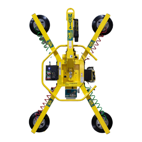
ROTATOR/TILTER,
DC-VOLTAGE WITH
INTELLI-GRIP® TECHNOLOGY
(Available with REMOTE CONTROL SYSTEM)
Model numbers: MRT411LDC3 (shown), MRT49DC3
Record serial number in blank space above (to locate, see serial
Rev 7.2/4-21
label on the product).
1
908 W. Main • P.O. Box 368
Laurel, MT USA 59044
800-548-7341 (phone)
406-628-8231 (phone)
406-628-8354 (fax)
www.WPG.com
MRT4-DC3: #35068
Advertisement
Table of Contents

Related Manuals for WOOD'S POWR-GRIP MRT411LDC3


Summary of Contents for WOOD'S POWR-GRIP MRT411LDC3
- Page 1 PROFESSIONALS • READ AND UNDERSTAND BEFORE OPERATING MANUAL ROTATOR/TILTER, DC-VOLTAGE WITH INTELLI-GRIP® TECHNOLOGY (Available with REMOTE CONTROL SYSTEM) Model numbers: MRT411LDC3 (shown), MRT49DC3 Record serial number in blank space above (to locate, see serial Rev 7.2/4-21 MRT4-DC3: #35068 label on the product).
- Page 2 MRT4-DC3: #35068 Rev 7.2/4-21...
-
Page 3: Table Of Contents
TABLE OF CONTENTS SPECIFICATIONS ..................3 SAFETY....................5 OPERATING FEATURES................6 ASSEMBLY....................7 ..........9 HANGE THE RAME ONFIGURATION Installing/Removing Extension Arms and Repositioning Vacuum Pads ......10 Using Secondary Rotation Stops ..................11 INTENDED USE ..................12 ................12 HARACTERISTICS ................13 PERATING NVIRONMENT ................13 ISPOSAL OF THE IFTER OPERATION..................14 ................14 EFORE... - Page 4 TABLE OF CONTENTS Storing the Lifter .......................26 INSPECTIONS AND TESTS..............28 ................28 NSPECTION CHEDULE ....................29 ESTING Lifter/Load Compatibility Test...................29 Operational Tests ......................30 Vacuum Test........................30 Rated Load Test.........................31 Remote Control System Test .....................31 MAINTENANCE ..................32 ...............32 ACUUM AINTENANCE Pad-to-Load Friction Coefficient ..................32 Pad Inspection ........................32 Pad Cleaning ........................33 12-V...
-
Page 5: Specifications
Designed for use with hoisting equipment, MRT4-DC3 lifters support loads using vacuum and manipulate Description loads using manual 360° rotation and manual 90° tilt motions. Model MRT49DC3 MRT411LDC3 Number 9" [23 cm] nominal diameter 11" [28 cm] nom. diameter, lipped Vacuum Pads... - Page 6 SPECIFICATIONS Note: A standard MRT411LDC3 is shown. MRT4-DC3: #35068 Rev 7.2/4-21...
-
Page 7: Safety
SAFETY Wear personal protective Make sure the contact surfaces of equipment that is appropriate for the load and vacuum pad are clean the load material. Follow trade before attaching the lifter (see association guidelines. “MAINTENANCE”). Do not remove or obscure safety Position the vacuum pads correctly labels. -
Page 8: Operating Features
24 LIFT BAR Not shown: EXTENSION ARMS Note: A standard MRT411LDC3 is shown. Although some of the following photos do not show this specific lifter, they all illustrate how this kind of lifter functions. For information about specific parts, see “REPLACEMENT PARTS”... -
Page 9: Assembly
ASSEMBLY Remove all shipping materials and save them with the shipping container for future use. 2) Suspend the lifter from appropriate hoisting equipment: 2.1) Select a crane and/or hoist rated for the Maximum Load Capacity plus the Lifter Weight. Note: Any lifter use must comply with all statutory or regulatory standards for hoisting equipment in your region. - Page 10 ASSEMBLY 2.4) Use the hoisting equipment to remove the lifter from the shipping container. Avoid damaging the vacuum pads. Connect the electrical connectors (figs. 3A-B and figs. 3C-D). Install the 9-volt battery for the notification buzzer as directed in “N OTIFICATION UZZER ATTERY...
-
Page 11: T O Change The Pad Frame Configuration
ASSEMBLY HANGE THE RAME ONFIGURATION Rev 7.2/4-21 MRT4-DC3: #35068... -
Page 12: Installing/Removing Extension Arms And Repositioning Vacuum Pads
ASSEMBLY Various pad frame configurations enable the lifter to match different load dimensions. The illustrations on the preceding page show all approved configurations. Dimensions show Pad Spread for a standard MRT411LDC(3) lifter (see “SPECIFICATIONS” on page 3 for other models). Caution: Position the vacuum pads for the 2 circuits of the dual vacuum system (marked “1”... -
Page 13: Using Secondary Rotation Stops
ASSEMBLY Using Secondary Rotation Stops Align the secondary rotation stops for correct use of the pad frame in long, narrow configurations. Rev 7.2/4-21 MRT4-DC3: #35068... -
Page 14: Intended Use
INTENDED USE HARACTERISTICS Make sure the vacuum lifter is intended Do NOT lift explosives, radioactive to handle each load according to these substances or other hazardous materials. requirements: • The load weight must not exceed the Maximum Load Capacity. • The load must be a single piece of relatively nonporous material with a flat and 1, 2 relatively smooth contact surface. -
Page 15: Operating Environment
INTENDED USE PERATING NVIRONMENT Make sure the vacuum lifter is intended for use in each work environment, given the following restrictions: • This lifter is not intended for any environment that is Never use lifter dangerous to the operator or damaging to the lifter. Avoid in dangerous environments containing explosives, caustic chemicals and environme... -
Page 16: Operation
OPERATION EFORE SING THE IFTER Determine whether the vacuum lifter is capable of each intended task (see “SPECIFICATIONS” “INTENDED USE”). Then complete the following preparations: Taking Safety Precautions • Be trained in all industry and regulatory Read all directions and safety standards for lifter operation in your region. -
Page 17: Performing Inspections And Tests
OPERATION Performing Inspections and Tests • Follow the “I ” “T ”. NSPECTION CHEDULE ESTING • Service the 2 air filters whenever a bowl contains Examine air filters regularly liquid or other contaminates, or an element and service when needed. appears dirty (see “A ”... -
Page 18: Preparing To Use The Remote Control System
OPERATION Preparing to Use the Remote Control System The optional radio transmitter (fig. 1A) and radio receiver enable you to activate the lifter's “attach” and “release” functions at distances up to 250' [76 m], provided you have a clear and direct view of the lifter and its status indicators. -
Page 19: T O Attach The Pads To A Load
OPERATION TTACH THE ADS TO A Make sure the contact surfaces of the load and vacuum pads are clean (see “Pad Cleaning”). Positioning the Lifter on the Load Center the pad frame on the load (fig. 1A). Make sure all vacuum pads will fit on the load and will be loaded evenly (fig. -
Page 20: Powering Up The Lifter
OPERATION Powering up the Lifter Press the lifter's power button ( — fig. 1A). The vacuum pump will run for a few seconds, ® as a normal function of the Intelli-Grip self- diagnostics. The lifter automatically tests the 9-volt battery for the notification buzzer each time the lifter is powered up. -
Page 21: Reading The Vacuum Gauges
OPERATION To use the optional Remote Control System, press the “attach” button ( — fig. 1D) on the radio transmitter. The vacuum pump will run until the vacuum pads seal completely. If the lifter takes too long to attach, the notification buzzer chirps and the LCD screen displays “Vacuum not increasing normally”, along with a diagnostic code (see... -
Page 22: T O Lift And Move The Load
OPERATION IFT AND OVE THE Lift bar must be vertical to lift load. Interpreting the Lift Light When the vacuum lifter is ready to lift Never lift load unless lift the Maximum Load Capacity, the light is illuminated, vacuum lift light turns on automatically and because premature lifting could the vacuum pump turns off temporarily, to result in load release and... -
Page 23: Controlling The Lifter And Load
OPERATION 2) Stop using the lifter until the cause of the vacuum loss can be identified: Conduct the “Pad Inspection” and perform the “Vacuum Test”. 3) Correct any faults before resuming normal operation of the lifter. Controlling the Lifter and Load When the lifter is ready, use the hoisting equipment to raise the lifter and load as needed. -
Page 24: T O Rotate The Load
OPERATION OTATE THE Make sure load is positioned correctly on lifter (as previously directed). Never disengage rotation and tilt latches at the same time, because this could result in load damage or personal injury. Make sure the load has enough clearance to rotate without contacting anyone or anything. -
Page 25: T O Tilt The Load
OPERATION ILT THE Make sure load is positioned correctly on lifter (as previously directed). Never disengage rotation and tilt latches at the same time, because this could result in load damage or personal injury. Make sure the load has enough clearance to tilt without contacting anyone or anything. - Page 26 OPERATION A load with overhang may force you to release the control handle as the load approaches the flat position. In this case, use hand cups (circled in fig. 1A) or other appropriate means to control the load. MRT4-DC3: #35068 Rev 7.2/4-21...
-
Page 27: T O Release The Pads From The Load
OPERATION ELEASE THE ADS FROM THE Make sure load is at rest and fully supported before releasing vacuum pads. 1) Hold the “function” button ( — fig. 1A) and the “release” button ( — fig. 1A). If the vacuum seal does not break, follow the directions on the LCD screen. -
Page 28: After Using The Lifter
OPERATION FTER SING THE IFTER Press the power button ( — fig. 1A) and the “function” button ( — fig. 1A) to power down the vacuum lifter. 2) Charge the battery after each workday as needed (see “12-V ATTERY ”). ECHARGE 3) Use the hoisting equipment to lower the lifter gently onto a stable support. - Page 29 OPERATION Disconnect the electrical connectors (figs. 3A-B and figs. 3C-E) to prevent battery discharge. 4) Store the lifter in a clean, dry location. Store the battery between 32° and 70° F [0° — 21° C]. Avoid storage above 100° F [38° C]. Rev 7.2/4-21 MRT4-DC3: #35068...
-
Page 30: Inspections And Tests
INSPECTIONS AND TESTS NSPECTION CHEDULE Perform inspections according to the following frequency schedule. If any fault is found, correct it and perform the next most frequent inspection before using the vacuum lifter. Note: If a lifter is used less than 1 day in a 2-week period, perform the Periodic Inspection before using it. -
Page 31: Testing
INSPECTIONS AND TESTS ESTING Perform the following test to determine whether or not a load surface is too porous or rough: Lifter/Load Compatibility Test 1) Make sure the vacuum generating system is functioning correctly (see “Vacuum Test”). 2) Thoroughly clean the load surface and the vacuum pads (see “Pad Cleaning”). -
Page 32: Operational Tests
INSPECTIONS AND TESTS Perform the following tests before placing the lifter in service initially and following any repair, when directed in the “I ”, or whenever necessary: NSPECTION CHEDULE Operational Tests Test all features and functions of the lifter (see “OPERATING FEATURES” and “OPERATION”). Vacuum Test 1) Clean the face of each vacuum pad (see “Pad... -
Page 33: Rated Load Test
INSPECTIONS AND TESTS Rated Load Test The following steps must be performed or supervised by a qualified person: 1) Use a test load that weighs 125% (± 5%) of the Maximum Load Capacity and has the appropriate “L ”. HARACTERISTICS 2) Attach the vacuum pads to the load as previously directed. -
Page 34: Maintenance
MAINTENANCE Note: Refer to SERVICE MANUAL #36106 when applicable. ACUUM AINTENANCE Pad-to-Load Friction Coefficient The friction coefficient represents the lifter's ability to resist load slippage. The Maximum Load Capacity is based on a friction coefficient of 1, as determined by testing of clean, new, standard rubber vacuum pads on clean, dry, regular glass. -
Page 35: Pad Cleaning
MAINTENANCE Pad Cleaning Regularly clean the face of each vacuum pad (fig. 1A), using soapy water or other mild cleansers to remove oil, dust and other contaminates. Never use harsh chemicals on vacuum pad. Solvents, petroleum-based products (including kerosene, gasoline and diesel fuel) or other harsh chemicals can damage vacuum pads. -
Page 36: 12-Volt Battery Recharge
MAINTENANCE 12-V ATTERY ECHARGE Charge the battery whenever the battery gauge shows reduced energy. Caution: Make sure the lifter is powered down. Identify the input voltage marked on the battery Make sure power source has charger and plug it in to an appropriate power ground fault circuit interrupter. -
Page 37: Notification Buzzer Battery Replacement
MAINTENANCE OTIFICATION UZZER ATTERY EPLACEMENT 1) Power down the lifter. 2) Release the buzzer battery holder by pressing inward and sideward in the direction marked on the holder. Slide the battery tray out (fig. 3A). 4) Install a new 9-volt battery according to the polarity markings. 5) Slide the battery tray back into position. -
Page 38: Ntelli Rip Iagnostic Odes
MAINTENANCE ® D NTELLI IAGNOSTIC ODES Refer to the following table when a diagnostic code appears on the LCD screen. Codes are listed in alphanumeric order. If the Explanations/Directions do not resolve the issue, contact qualified service personnel. All relevant parts are listed in “REPLACEMENT PARTS”. - Page 39 MAINTENANCE Strobe Buzzer Code On-Screen Message Light Explanations/Directions Pattern Activity continuous Once “Power Save” mode is activated, “attach” and “Control head revision lockout” (while button (none) “release” functions are prevented in connection with Code is held) C06. Service is required. occasional “EEPROM error, cell #”...
- Page 40 MAINTENANCE Strobe Buzzer Code On-Screen Message Light Explanations/Directions Pattern Activity Use only “function” button and “power” button to power (possi- “Turn off? Let go of buttons” (none) down lifter. Lifter cannot be powered down while any ble) other button is pressed. Timed release function is activated for number of seconds 1 chirp per shown (see...
- Page 41 MAINTENANCE Strobe Buzzer Code On-Screen Message Light Explanations/Directions Pattern Activity Vacuum pump is running more often than normal. Likely causes include significant vacuum leak or difficulty achieving minimum vacuum level due to high elevation. V03A 1 chirp every “Pump running excessively” (none) In case of suspected leak, check for fault(s) in vacuum V03B...
-
Page 42: Replacement Parts
REPLACEMENT PARTS Stock No. Description Qty. 65442CA Vacuum Hose – 0.160" ID x 1/4" OD – Red 65442AM Vacuum Hose – 0.245" ID x 3/8" OD x 48" Length – Coiled – Green 65441 Vacuum Hose – 0.245" ID x 3/8" OD x 48" Length – Coiled – Red 65440 Vacuum Hose –... -
Page 43: Limited Warranty
For purchases in all other localities: Contact your dealer or the WPG Technical Service Department for assistance. WPG may be reached by phone or fax numbers listed below. Wood's Powr-Grip Co., Inc. 406-628-8231 (phone) 908 West Main St. 800-548-7341 (phone) - Page 44 908 W. Main • P.O. Box 368 Laurel, MT USA 59044 800-548-7341 (phone) • 406-628-8231 (phone) 406-628-8354 (fax) • www.WPG.com INTENDED FOR USE BY SKILLED TECHNICAL PROFESSIONALS • READ AND UNDERSTAND BEFORE ROUTING, WIRING AND/OR ASSEMBLING MANUAL ROTATOR/TILTER, DC-VOLTAGE WITH INTELLI-GRIP® TECHNOLOGY Model numbers: MRT49DC3, MRT411LDC3...
Need help?
Do you have a question about the MRT411LDC3 and is the answer not in the manual?
Questions and answers