Table of Contents

Subscribe to Our Youtube Channel
Related Manuals for NKE ULTRASONIC SPEEDO

Summary of Contents for NKE ULTRASONIC SPEEDO
- Page 1 ULTRASONIC SPEEDO sensor Product reference : 90-60-479 REV 1 USER GUIDE INSTALLATION GUIDE Sailing competition Z.I. Kerandré – Rue Gutenberg – 56700 HENNEBONT- FRANCE http://www.nke.fr – N° indigo 0 892 680 656 : 0,34€/min.
-
Page 2: Table Of Contents
1.7 T ....................5 ECHNICAL SPECIFICATIONS 1.8 D ................ 6 IAGNOSTIC OF LEVEL TROUBLESHOOTING USE OF THE ULTRASONIC SPEEDO ON NMEA OR PADDLEWHEEL OUTPUT .... 7 2.1 C NMEA ................7 HARACTERISTICS OF THE OUTPUT 2.2 C ..............7... -
Page 3: Use
Two types of installation are possible : − The ULTRASONIC SPEEDO is connected to the TOPLINE bus of your installation, via the loch sounder interface. − As an autonomous sensor, with a 12V power supply, the ULTRASONIC SPEEDO provides the information on speed, via an NMEA0183 output or a Paddlewheel output. -
Page 4: List Of Channels Displayed
For channel setting, please refer to your TOPLINE display user guide. 1.2 List of channels displayed The ULTRASONIC SPEEDO sensor, connected to the nke TOPLINE bus, automatically creates the channels below. They are accessible using the displays of the TOPLINE range.. -
Page 5: Filtering Of The Channels
Storage temperature : -20° C to +60° C. Speed measurement range : 0.3 to 50 knots. Resolution : 1/100th of a knot. Accuracy < 1% for laminar flow. Temperature measurement range : 0° C to +50° C. Ultrasonic Speedo sensor - 33-60-043-000... -
Page 6: Diagnostic Of St Level Troubleshooting
Before contacting technical support, please check the troubleshooting table below. The ULTRASONIC SPEEDO sensor comprises a two-colour LED that indicates the state of the sensor : The table below provides you with the operating state or the type of fault of the Ultrasonic... -
Page 7: Use Of The Ultrasonic Speedo On Nmea Or Paddlewheel Output
The ULTRASONIC SPEEDO contains a NMEA output, and a Paddlewheel output, which deliver a signal identical to that of a paddlewheel. Thus, without using a TOPLINE nke bus, you can connect the ULTRASONIC SPEEDO sensor directly into your electronic navigation system. -
Page 8: Connection Of The Nmea Or Paddlewheel Outputs
To start this test, the black wire of the sensor must be connected to the ground before to power on the sensor. 18 seconds after the Ultrasonic Speedo sensor is powered on (black wire still connected to the ground) the sensor executes 3 test cycles during 24 seconds with a... -
Page 9: Sensor Calibration
SENSOR CALIBRATION Every nke sensor is adjusted at the factory. However, a calibration is required to adapt to the specificities of your ship and to obtain an optimum measurement accuracy. Follow the calibration procedure below, by visualising the settings on a display. To perform these settings, please refer to the user guide of your display. -
Page 10: Installation
INSTALLATION 4.1 Packing list The ULTRASONIC SPEEDO sensor comes equipped with a 10 metre cable, a waterproof connector, sealing joints and the clamping nut. User and installation guide 4.2 List of accessories Installation kit of the loch through-hull, stopper and tube of silicon grease : 31-35-001 Adapter for through-hull fitting with a diameter : 2”... - Page 11 10 to 15 mm streamlined plate so that the sensor is located beyond the turbulent water layers. Pressure area 1/3 L Displacement hull Speed boat Planing hull Horseshoe hull Sailing boat Figure 3 : recommended locations for the speedometer Figure 3 sensor 11 - Ultrasonic Speedo sensor - 33-60-043-000...
-
Page 12: Installation Of The Through-Hull
Note : a flat joint is supplied with the through-hull, for the water tightness between the hull and the through-hull. However, the installation of this joint is not essential. For a more reliable water tightness with time, we recommend that you only use sealing paste. 12 - Ultrasonic Speedo sensor - 33-60-043-000... -
Page 13: Installation Of The Ultrasonic Speedo Sensor
4. 4.8 Adapter for the old nke through-hull : 31-36-002 If your ship is already equipped with an nke through-hull (ref : 31-01-006), you can use the adapter reference 31-36-002 to install the ULTRASONIC SPEEDO sensor. This adapter allows you to install the sensor into the diameter of the old through-hull easily and with no tools. -
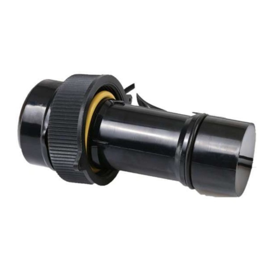
Page 14: Electrical Connection To The Topline Loch Sounder Interface
4.9 Electrical connection to the Topline Loch Sounder Interface The sensor is equipped with a 10 metre cable and a waterproof connector. You will connect the ULTRASONIC SPEEDO sensor onto the connector socket marked speed sensor of the loch sounder interface housing. - Page 15 NOTES _____________________________________________________________________________________________________ _____________________________________________________________________________________________________ _____________________________________________________________________________________________________ _____________________________________________________________________________________________________ _____________________________________________________________________________________________________ _____________________________________________________________________________________________________ _____________________________________________________________________________________________________ _____________________________________________________________________________________________________ _____________________________________________________________________________________________________ _____________________________________________________________________________________________________ _____________________________________________________________________________________________________ 15 - Ultrasonic Speedo sensor - 33-60-043-000...
- Page 16 NOTES _____________________________________________________________________________________________________ _____________________________________________________________________________________________________ _____________________________________________________________________________________________________ _____________________________________________________________________________________________________ _____________________________________________________________________________________________________ _____________________________________________________________________________________________________ _____________________________________________________________________________________________________ _____________________________________________________________________________________________________ _____________________________________________________________________________________________________ _____________________________________________________________________________________________________ _____________________________________________________________________________________________________ 16 - Ultrasonic Speedo sensor - 33-60-043-000...
Need help?
Do you have a question about the ULTRASONIC SPEEDO and is the answer not in the manual?
Questions and answers