Table of Contents
Advertisement
Quick Links
Advertisement
Table of Contents

Related Manuals for Locinox SlimStone-2


Summary of Contents for Locinox SlimStone-2
- Page 1 SlimStone-2 MANUAL SlimStone-2...
- Page 2 NOTICE The contents of this publication are subject to change. The Locinox Corporation reserves the right to alter the contents of this publication at any time and without notice. The contents of this publication may contain inaccuracies or typographical errors and is supplied for informational use only.
- Page 3 SlimStone-2 MANUAL SlimStone-2...
- Page 4 SlimStone-2 Up to 100 entry codes Extreme weather proof IP 68 Control inputs included Freeze-free by heating element Easily readable digits by LED lighting Ultimate durable components SlimStone-2...
- Page 5 BOX CONTENT 54 mm 23,8 mm 2-1/8” 15/16” SLIMSTONE-2 27 mm 1-1/16” SlimStone-2 Allen key 6 mm Allen key 2,5 mm Wall mounting set Heat Shrinking Tubing (6x) Drilling template SlimStone-2...
-
Page 6: Table Of Contents
CONTENTS PRODUCT DESCRIPTION ..................TECHNICAL SPECIFICATIONS ................MOUNTING ......................CABLING ......................PRIORITY CONTACT ................... PROGRAMMING ....................FUNCTIONING OF SLIMSTONE-2 ..............MAINTENANCE ....................GENERAL INFORMATION ................. WARRANTY ......................1 1. TROUBLESHOOTING ..................FREQUENTLY ASKED QUESTIONS ..............USER CODES ....................... CONNECTION SCHEME ................... -
Page 7: Product Description
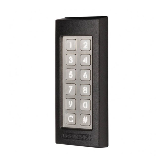
Equipped with innovative Quick-Fix, alternative fixings for wood and stone are also supplied. The SlimStone-2 is made of an aluminium powder coated housing with a brushed stainless steel key panel and ditto push buttons. Up to 100 codes can be programmed. - Page 8 STEP 3A STEP 4 Run the cable through the middle hole in the post. Position the SlimStone-2 and tighten both Quick-Fix. 6 mm STEP 3B STEP 5 Run the cable through the middle hole in the wall. Position the cover and tighten using 2 screws underneath.
-
Page 9: Cabling
CABLING PROGRAMMING The SlimStone-2 is equipped with a 2 m long 10 6.1 ACCESS PROGRAMMING conductor cable. MODE See p. 63 for a detailed connection scheme. • Press [#] for 5 sec, [#] will start flashing Power supply • Enter the Master PIN and press [#] (default 12345). - Page 10 • You will return to the main menu • Enter a new PIN code and confirm with [#] Pulse mode: if the SlimStone-2 is used to control • In case of a new code, the code will need to be automated systems, a pulse is required.
-
Page 11: Functioning Of Slimstone-2
• Press [1], [2] or [3] and confirm with [#]. When • If the sequence light stops, the relay is no longer all LEDs flash, your choice has been saved. energised. The SlimStone-2 is ready for a new code. • You are back in the main menu of the programming mode 7.2 ENTER A WRONG CODE... -
Page 12: Maintenance
0V/N line. Please note that codes need to be programmed on both SlimStone-2’s. A discarded device can either be returned to your dealer or be sent back to Locinox. This product’s recycling fee is € 0,2. The WEE marking on the product indicates that it may not be thrown away together with normal household waste and must be handed over to a designated collection point for the recycling of electrical and electronic rejects. -
Page 13: User Codes
• - USER CODES NAME OF USER SlimStone-2... - Page 14 USER CODES NAME OF USER SlimStone-2...
- Page 15 • - USER CODES NAME OF USER SlimStone-2...
- Page 16 USER CODES NAME OF USER SlimStone-2...
- Page 17 • - USER CODES NAME OF USER SlimStone-2...
-
Page 18: Connection Scheme
H Normal close relay 2 CONTROL INPUT 2 C Common Relay 1 F Common Relay 2 Power RELAY 2 CONTROL INPUT 1 CONTROL INPUT 2 220V RELAY 1 DC-POWER 12V/20W RELAY 2 CONTROL INPUT 1 220V RELAY 1 DC-POWER 12V/20W FAIL OPEN SlimStone-2... - Page 19 Whilst every effort has been made to ensure the accuracy of the information supplied. F.H. Brundle cannot be held responsible for any errors or omissions. This product must only be employed for its original intended use. Any other use is wrong and potentially dangerous. Installation must be carried out in full compliance with current regulations.
Need help?
Do you have a question about the SlimStone-2 and is the answer not in the manual?
Questions and answers
hoe moet ik de motor aansturen ( aansluiten ) en ook het magneetslot