
Related Manuals for Schleuniger CoaxCenter 6000


Summary of Contents for Schleuniger CoaxCenter 6000
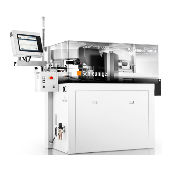
- Page 1 CoaxCenter 6000 Automatic Coaxial Cable Cut & Strip Machine Reference Manual Software Version 2.2x |Edition 5.0 (09-2016) 1 | 194 Reference Manual |Edition 5.0 (09-2016) |CoaxCenter 6000...
- Page 2 The German edition of this document is the original Instructions. Translation of the original Instructions All non German language editions of this document are translations of the original Instructions. © 2016 Schleuniger | ID-0000000212-005-EN Publication type variant: Extract 2 | 194 Reference Manual |Edition 5.0 (09-2016) |CoaxCenter 6000...
- Page 3 Page 79 CONFIGURATION ▸ Page 99 ▸ Configuration and pre-settings on machine and control software. Page 107 MAINTENANCE ▸ Page 127 Maintenance of the product, maintenance schedule, troubleshooting, soft- ware upgrade. 3 | 194 Reference Manual |Edition 5.0 (09-2016) |CoaxCenter 6000...
- Page 4 Topic list 4 | 194 Reference Manual |Edition 5.0 (09-2016) |CoaxCenter 6000...
-
Page 5: Table Of Contents
........... POSITION OF CENTER OF GRAVITY FOR THE COAXCENTER 6000 . - Page 6 ............6 | 194 Reference Manual |Edition 5.0 (09-2016) |CoaxCenter 6000...
- Page 7 Description..............7 | 194 Reference Manual |Edition 5.0 (09-2016) |CoaxCenter 6000...
- Page 8 ............8 | 194 Reference Manual |Edition 5.0 (09-2016) |CoaxCenter 6000...
- Page 9 ............INDEX 9 | 194 Reference Manual |Edition 5.0 (09-2016) |CoaxCenter 6000...
- Page 10 Table of contents 10 | 194 Reference Manual |Edition 5.0 (09-2016) |CoaxCenter 6000...
-
Page 11: General
1. General GENERAL Thank you for your trust in the Schleuniger technique! You have acquired a high performance Schleu- niger product, designed and manufactured in our factory to your needs. Read through this manual with due care and attention. It contains important tips and safety instructions, which allow precise and reliable production. -
Page 12: Safekeeping
The contents must remain clearly legible beyond the expected lifespan of the product. ■ SYMBOLS The symbols are placed in the marginal notes column and refer to the adjacent text. They have the following meaning: 12 | 194 Reference Manual |Edition 5.0 (09-2016) |CoaxCenter 6000... -
Page 13: Legend
Direction of rotation for a component or an operating element viewed from rotation axis. Counter clockwise Direction of rotation for a component or an operating element viewed from rotation axis. 13 | 194 Reference Manual |Edition 5.0 (09-2016) |CoaxCenter 6000... -
Page 14: Declaration Of Conformity
The rights for other brands and product names in these instructions are deposited by their owners and must be accepted herewith. Mentioning products not manufactured by Schleuniger is intended exclusively for information purposes. It does not constitute advertising. Schleuniger is not responsible in terms of selection, performance or usability of this products. -
Page 15: Safety
Maintenance and repair ■ Disposal ■ Qualified personnel Technical skill ■ Qualification Product-specific training ■ Know-how in wire processing technics ■ Operating ■ Programming ■ Authority / activity Instructor ■ Maintenance ■ 15 | 194 Reference Manual |Edition 5.0 (09-2016) |CoaxCenter 6000... -
Page 16: Warning Notices
This panel indicates a potential hazardous situation, which if not avoided, may result in minor or moderate injury. CAUTION PROPERTY DAMAGE NOTICE "Property damage" This panel indicates a hazardous situation, which if not avoided, can result in damage to property. 16 | 194 Reference Manual |Edition 5.0 (09-2016) |CoaxCenter 6000... -
Page 17: General Safety Notes
Only use original Schleuniger equipment, especially interface connection cables (electromagnetic ■ compatibility). Compulsory operate the product connected to the Schleuniger emergency stop circuit, if it is ■ operated together with peripheral devices in a production line. Only then can a safe interruption of the complete production line be guaranteed during an emergency. -
Page 18: Safety Symbols In Manual
Electronic components react sensitive to static charge. Spe- tive components! cially marked components and packaging must only be han- dled by trained personnel after a potential equalization and with special equipment. 18 | 194 Reference Manual |Edition 5.0 (09-2016) |CoaxCenter 6000... -
Page 19: Safety Symbols On Product
RETROFITTING Without written permission of Schleuniger, do not make changes or any retrofit work on the product. The performance and the safety is affected thereby. Standard options and accessories supplied by Schleuniger are excluded therefrom. -
Page 20: Transportation
The arrows point to the top side of the packaging. Store and transport the packaging upright. Do not tilt. Avoid moistness Store and transport the packaging protected against moist- ness. 20 | 194 Reference Manual |Edition 5.0 (09-2016) |CoaxCenter 6000... -
Page 21: Transport Inspection
On recognizable loss during shipment proceed as follows: Do not accept the delivery or only with retentions ■ Declare loss of shipment ■ Immediately report damages on the product to the shipping company or the vendor ■ 21 | 194 Reference Manual |Edition 5.0 (09-2016) |CoaxCenter 6000... - Page 22 3. Transportation 22 | 194 Reference Manual |Edition 5.0 (09-2016) |CoaxCenter 6000...
-
Page 23: Product Specifications
As limits the areas in the technical data apply. Any other use of this product is regarded as non-inten- ded use. For damages arising therefrom, Schleuniger is not liable. Reasonably foreseeable misuse 4.1.2 The product CoaxCenter 6000 is not intended for the processing of materials with the following char- acteristic: Explosive ■... -
Page 24: Dimensions And Weight
DIMENSIONS AND WEIGHT Fig. 1: Measures base layout Description Value Unit Weight Net (base machine) Measures Length 1300 Length including wire straightener and 2000 stacker Width Height 2170 Tab. 1: Dimensions/weight 24 | 194 Reference Manual |Edition 5.0 (09-2016) |CoaxCenter 6000... -
Page 25: Position Of Center Of Gravity For The Coaxcenter 6000
4. Product specifications POSITION OF CENTER OF GRAVITY FOR THE COAXCENTER 6000 Position of center of gravity Fig. 2: Position of center of gravity During transportation observe the position of center of gravity. Packaged, observe the markings on the packaging. -
Page 26: Requirements On The Installation Location
Position the machine easily accessible for handling on an even, stable ground. Apply a safety fence around the machine if positioned close to a passageway (e. g. a handrail), to avoid touching the rotating pre-feeding units or other moving machine parts. 26 | 194 Reference Manual |Edition 5.0 (09-2016) |CoaxCenter 6000... -
Page 27: Rating Plate
The rating plate with the serial number and the electric data is placed on the left close to the power plug socket. 27 | 194 Reference Manual |Edition 5.0 (09-2016) |CoaxCenter 6000... - Page 28 2 x T10 AH 200/240 VAC 50/60 Hz 800 VA Weight: 410 kg Made in Switzerland Product type Machine weight Serial number/manufacture year Power consumption Permitted mains voltage Fuse rating Line frequency 28 | 194 Reference Manual |Edition 5.0 (09-2016) |CoaxCenter 6000...
-
Page 29: Product Description
The CoaxCenter 6000 is designed for cutting and stripping of coaxial cables, as well as single conduc- tor wires and other material in the range of AWG 40 to 5.5 mm outer diameter. The CoaxCenter 6000 is of a flexible design extendable with processing stations for crimp, tin and/or window stripping. Fur- thermore it can be completed with a quality control station for stripping and individual stackers. -
Page 30: Base Unit / Options
Used for stiff conductors. ■ NAS (Network Access Storage) device: Saving of pictures from the Q-Cam 360 analysis. ■ Tower light: Display of the operational state, before, during and after the production. ■ 30 | 194 Reference Manual |Edition 5.0 (09-2016) |CoaxCenter 6000... -
Page 31: Overview Of Components
Dial Production speed Pressure control collector Safety hood open/close Stacker Interfaces (control box) Control compartment electronics Raw material inlet/wire straightener Maintenance unit compressed air Tower light Compressed air control gripper/feeding 31 | 194 Reference Manual |Edition 5.0 (09-2016) |CoaxCenter 6000... -
Page 32: Further Elements
5. Product description Further elements 5.2.2 Fig. 6: Elements on left machine cover Mains fuses Compressed air control feeding unit Line disconnecter Compressed air control gripper 32 | 194 Reference Manual |Edition 5.0 (09-2016) |CoaxCenter 6000... -
Page 33: Power And Compressed Air Connector
5. Product description Power and compressed air connector 5.2.3 Fig. 7: Power/compressed air Compressed air input Power input Maintenance unit 33 | 194 Reference Manual |Edition 5.0 (09-2016) |CoaxCenter 6000... -
Page 34: Processing Stations Base Machine
Cutting unit Q-Cam 360 (side 2) Q-Cam 360 (side 1) Rotary incising unit] (side 2) Rotary incising unit (side 1) Connections / interfaces 5.2.5 USB-connector (operating unit): Operating unit rear: 34 | 194 Reference Manual |Edition 5.0 (09-2016) |CoaxCenter 6000... - Page 35 5. Product description Interfaces (control box rear): USB connector ETHERNET interface SC-memory card slot Connector status lamp Swiveling mechanism operating unit Prefeeder interface Connector operating unit 35 | 194 Reference Manual |Edition 5.0 (09-2016) |CoaxCenter 6000...
-
Page 36: Safety Installations
Safety cover switch Danger zones 5.2.7 The dangerous zones on the CoaxCenter 6000 are marked in the following figure. The user must addi- tionally inform him selves about residual risks. See chapter "2.5 Residual risks (Page 17)". 36 | 194... - Page 37 Turn off the main switch, block against switching on again and disconnect the machine from the ■ mains (for hard wired machines, the main switch serves as a mains disconnecter). Unplug the machine from the compressed air supply. ■ 37 | 194 Reference Manual |Edition 5.0 (09-2016) |CoaxCenter 6000...
- Page 38 On the outlet the produced articles are fed at high speed out of the machine. Escaping articles can injure eyes, face and other parts of the body. Do not stay in this area and do not steer into the outlet during production. 38 | 194 Reference Manual |Edition 5.0 (09-2016) |CoaxCenter 6000...
-
Page 39: Description Of Operating Elements / Components
5.3.1 Mains disconnecter Via the mains disconnecter on the left of the machine, the CoaxCenter 6000 is completely cut from the mains supply. For any maintenance work the mains disconnecter must be turned off and locked against switching on again with a locker. - Page 40 Activity by operator Emergency An error is pending Immediate action pending to react to (dangerous state) a dangerous state. Abnormal YELLOW A warning is pending Monitor and/or react (potential critical state) 40 | 194 Reference Manual |Edition 5.0 (09-2016) |CoaxCenter 6000...
- Page 41 Via the USB connector, additionally a software upgrade ca be carried out. On the rear there is a slot for a CFast type memory card, where additional data can be saved. 41 | 194 Reference Manual |Edition 5.0 (09-2016) |CoaxCenter 6000...
- Page 42 The pressure depends on the to be processed raw material. The pressure should be set as low as pos- sible, to ensure that the raw material is fed properly but with no marks on the insulation. 42 | 194 Reference Manual |Edition 5.0 (09-2016) |CoaxCenter 6000...
-
Page 43: Raw Material Supply
The raw material diameter can be set on the dial in the range from 0.5 to 5.5 mm. Always select the next higher diameter step on the dial. 43 | 194 Reference Manual |Edition 5.0 (09-2016) |CoaxCenter 6000... -
Page 44: Optional Stations
The evaluated contact pressure for a certain raw material type can be read from the scale and fil- led in to a chart for later use. 44 | 194 Reference Manual |Edition 5.0 (09-2016) |CoaxCenter 6000... - Page 45 The module normally does not require any maintenance, hence take care that no slug or dust is deposited on the optic. It would affect the final result significantly or avoid analysis. 45 | 194 Reference Manual |Edition 5.0 (09-2016) |CoaxCenter 6000...
-
Page 46: Connections / Interfaces
"4.6 Rating plate (Page 27)". ■ The CoaxCenter 6000 is connected to the local mains supply through the power cord on the left of the machine. USB connector For the data backup and restore of settings and for loading a new software update there is on the right of the operating unit a slot for connecting an USB memory stick. -
Page 47: Delivery / Accessories
5. Product description ETHERNET connector The CoaxCenter 6000 can be connected directly or via a company network to a PC through the ETHER- NET connector. Therewith pictures from the produced article made by the Q-Cam 360 can this way be analyzed on the PC. - Page 48 5. Product description 48 | 194 Reference Manual |Edition 5.0 (09-2016) |CoaxCenter 6000...
-
Page 49: Installation / First Commissioning
UNPACKING / POSITIONING Lifting machine off the packaging 6.2.1 The CoaxCenter 6000 is delivered in a wooden box. Accessories and tools are contained in a cardboard box inside the main container. 49 | 194 Reference Manual |Edition 5.0 (09-2016) |CoaxCenter 6000... -
Page 50: Power Connection
There is a risk of an electric shock in the area of the power connector and the fuses which can lead to injury when touching electric components. Do not touch electric connections. 50 | 194 Reference Manual |Edition 5.0 (09-2016) |CoaxCenter 6000... -
Page 51: Positioning / Mounting / Switch-On
11.▹ Take out the stacker unit from the accesso- ries box and hook in on the right side of the CoaxCenter 6000. 12.▹ Fixate the stacker unit with the locking lev- 51 | 194 Reference Manual |Edition 5.0 (09-2016) |CoaxCenter 6000... - Page 52 16.▹ Plug-in the stacker unit to the appropriate connector of the CoaxCenter 6000. 17.▹ On the left side of the CoaxCenter 6000, attach the operating unit to the extender. 52 | 194 Reference Manual |Edition 5.0 (09-2016) |CoaxCenter 6000...
- Page 53 "6.2.4 Mounting options (Page 54)", otherwise: 22.▹ If options are available, go to chapter 23.▹ Switch on the machine on the mains disconnecter. 24.▹ Move the safety cover down via the [CLOSE] key. 53 | 194 Reference Manual |Edition 5.0 (09-2016) |CoaxCenter 6000...
-
Page 54: Mounting Options
1.▹ Disassemble the entry guide. 2.▹ Screw on the wire straightener to the con- trol box with the four hex screws . Tower light 1.▹ Attach the tower light on top and fixate. 54 | 194 Reference Manual |Edition 5.0 (09-2016) |CoaxCenter 6000... -
Page 55: Commissioning / Sample Cable
COMMISSIONING / SAMPLE CABLE During Commissioning of the CoaxCenter 6000, 10 coaxial cables are cut to length and stripped in sev- eral layers with the rotary incising unit on both sides. For our sample, the CoaxCenter 6000 is equipped with the following components: Rotary incising unit ■... - Page 56 ➥ 4.▹ On the touch keyboard enter „12“ (for pro- grammer) 5.▹ [OK] The article editor is shown. This is the main platform where the sample article is program- med. 56 | 194 Reference Manual |Edition 5.0 (09-2016) |CoaxCenter 6000...
- Page 57 The pressure should be as low as possible but high enough to catch and/or feed the raw material properly. But also take care that during the production no marks are left on the jack- 57 | 194 Reference Manual |Edition 5.0 (09-2016) |CoaxCenter 6000...
-
Page 58: Article Programming
6. Installation / first commissioning Article programming 6.3.2 1.▹ [LEAVE SCREEN] 2.▹ Touch (new article). 3.▹ On the touch keyboard enter the name of the article „Cable AWG36-1.13“. 4.▹ [ENTER] 58 | 194 Reference Manual |Edition 5.0 (09-2016) |CoaxCenter 6000... - Page 59 Back to the article editor. ➥ [RAW MATERIAL EDITOR] 6.▹ The Raw Material editor is shown. ➥ 7.▹ Enter the values according to the sample screen. [LEAVE SCREEN] 8.▹ 59 | 194 Reference Manual |Edition 5.0 (09-2016) |CoaxCenter 6000...
- Page 60 Bellow the article, the Processing for each layer can be changed. 13.▹ For each layer touch the corresponding [PROCESSING] pictogram and enter the values according to the following screens. 60 | 194 Reference Manual |Edition 5.0 (09-2016) |CoaxCenter 6000...
- Page 61 19.▹ [LEAVE SCREEN] 20.▹ Change the global values for rotary incis- ing unit. [LEAVE SCREEN] 21.▹ [TOLERANCE EDI- 22.▹ Touch the pictogram TOR]. The tolerance editor is shown. ➥ 61 | 194 Reference Manual |Edition 5.0 (09-2016) |CoaxCenter 6000...
- Page 62 30.▹ Change to the tab "Swivel arm 1". 31.▹ Enter the values for the swivel arm accord- ing to the screen. 32.▹ Change to the tab "Cut". 62 | 194 Reference Manual |Edition 5.0 (09-2016) |CoaxCenter 6000...
- Page 63 The numeric touch-keyboard pops-up. ➥ 40.▹ Enter the length = 60 mm [ENTER] 41.▹ 42.▹ Enter the quantity of articles = 10. 43.▹ Enter the quantity of batches = 5. 63 | 194 Reference Manual |Edition 5.0 (09-2016) |CoaxCenter 6000...
-
Page 64: Mounting Guides / Loading Raw Material
4.▹ On the dial above the swivel unit, set the gripper opening to = 1.2 mm. 64 | 194 Reference Manual |Edition 5.0 (09-2016) |CoaxCenter 6000... -
Page 65: Producing Article / Inspection
"Quantity" field. [RUN] The entered quantity is produced in ■ one single run. Then the machine stops and the batch can be confirmed. 65 | 194 Reference Manual |Edition 5.0 (09-2016) |CoaxCenter 6000... - Page 66 If this occurs, the programmed settings must be checked again or however the tolerance limits must be extended. Via the keys the individual produced articles within the processed batch can be selected. 66 | 194 Reference Manual |Edition 5.0 (09-2016) |CoaxCenter 6000...
-
Page 67: General Handling / Operation
Clean the housing and the processing area. ■ After 1 month: Check ventilator filter. ■ Additional maintenance work 7.4.2 For more information, see chapter "13 Maintenance / maintenance schedule (Page 127)". 67 | 194 Reference Manual |Edition 5.0 (09-2016) |CoaxCenter 6000... -
Page 68: Control Software
Header line Content area Footer line Visual representation of the operating elements and pictograms 7.5.2 Depending on the state of the operating elements they are distinguished with their color and shape: 68 | 194 Reference Manual |Edition 5.0 (09-2016) |CoaxCenter 6000... -
Page 69: Production Keys / Machine State / Info Area
Library for the crimp terminals Configuration PreFeeder, guides, Station (feeding unit, swivel arm, cutting unit, rotary incising unit), stacker, ETHERNET-interface, Time/Date, touch screen. User User interface (language, units, Time/Date), user level management. 69 | 194 Reference Manual |Edition 5.0 (09-2016) |CoaxCenter 6000... -
Page 70: Content Area
Key for turning on or off a function or a procedure. Other elements and symbols related to these functional elements, entry fields and graphics which are not assigned to a function in the selected state are grayed out or disappear completely. 70 | 194 Reference Manual |Edition 5.0 (09-2016) |CoaxCenter 6000... - Page 71 The keyboard is displayed by directly touching the to be changed entry field or after the command (new article). [RETURN] [CANCEL] The entry is confirmed with or however discarded with 71 | 194 Reference Manual |Edition 5.0 (09-2016) |CoaxCenter 6000...
- Page 72 Error: Red bar ■ Information An information is shown if the CoaxCenter 6000 outputs a message or if a user action is pending. Warning A warning is shown if a requested action from the user is risky (e. g. data loss).
- Page 73 Here the file name of the article is renamed. For this the alpha-numeric touch keyboard pops-up. Import/export article The selected article is saved to an USB memory stick or reloaded from the USB memory stick. 73 | 194 Reference Manual |Edition 5.0 (09-2016) |CoaxCenter 6000...
-
Page 74: Functional Elements In The Header Area
One or several articles can here be marked as write protected against inadvertent overwrite or delete. Functional elements in the header area 7.5.8 Production keys In the header area of the touch screen, the keys for the production control of the CoaxCenter 6000 are located. Production keys Load / unload A raw material is loaded automatically on the machine. - Page 75 After a batch is produced, the confirm message is shown. Keys in the info area These are main function keys which can be used for the whole functioning of the CoaxCenter 6000 and which are always visible. 75 | 194...
- Page 76 Default passwords: User level Password Operator Programmer Maintenance „About...“ screen: After touching “About.." the current software version, the creation date of this and other information is displayed. 76 | 194 Reference Manual |Edition 5.0 (09-2016) |CoaxCenter 6000...
- Page 77 In the header line of the touch screen we find additional data: Version of the control software Actual system- date/time Global production speed (see chapter "5.3.1.6 Production speed dial (Page 41)") 77 | 194 Reference Manual |Edition 5.0 (09-2016) |CoaxCenter 6000...
- Page 78 7. General handling / operation 78 | 194 Reference Manual |Edition 5.0 (09-2016) |CoaxCenter 6000...
-
Page 79: Programming Of Articles / Production
DESCRIPTION OF MAIN FUNCTIONS Raw Material editor 8.2.1 Opens the editor where the Raw Material is programmed. This way the individual nature of the article can be defined. Name ■ 79 | 194 Reference Manual |Edition 5.0 (09-2016) |CoaxCenter 6000... -
Page 80: Processing Editor
Resets all production counters back to their initial state. This function is used when a new production run is to be started. Produced articles, remaining articles and -batches are reset. Resetting the counter values must be confirmed via a safety message. 80 | 194 Reference Manual |Edition 5.0 (09-2016) |CoaxCenter 6000... -
Page 81: Batch On / Off
For the analysis of the scanned article data of the produced article (left or ■ right end). Wire type: Here we can select between single conductor- and multi layer cables. ■ 81 | 194 Reference Manual |Edition 5.0 (09-2016) |CoaxCenter 6000... -
Page 82: Multi-Layer Cable
Overview 8.4.1 The way in which the CoaxCenter 6000 processes a certain type of raw materials is defined in the Pro- cessing. The processing describes in detail, how the machine has to produce a certain raw material type. This is determined by data such as processing speed, incising depth, way back, air jet, utilized blades etc. -
Page 83: Swivel Unit Side 1 / 2
100 % the largest selectable value Acceleration [%] This setting changes the acceleration speed of the swivel arm, whereas 0 is the ■ smallest and 100 % the largest selectable value 83 | 194 Reference Manual |Edition 5.0 (09-2016) |CoaxCenter 6000... -
Page 84: Cut
■ Safe open: Opens slowly, also short cables fall down controlled into the tray. ■ 8.4.4 Involves settings for the cutting movement on the cutting unit during cutting to length. 84 | 194 Reference Manual |Edition 5.0 (09-2016) |CoaxCenter 6000... -
Page 85: Options
The residue is just cut. ■ Site - discard: The residue is cut in small pieces. ■ Options 8.4.5 Concerns additional optional stations built into the CoaxCenter 6000. Post-processing Selection of the post-processing device No Post Processing ■ Passive wire stacker ■... -
Page 86: Applications
Here additional Raw Material details to the article can be entered (stripping length, processing values etc.). Depending on the application type, more or less operation steps are available. 86 | 194 Reference Manual |Edition 5.0 (09-2016) |CoaxCenter 6000... - Page 87 This determines the stripping length on the individual layers of the raw material (jacket, shield, dielec- tric). Tolerance limits After touching a list entry, the tolerance editor is opened. The key is not available if partial strip is active. 87 | 194 Reference Manual |Edition 5.0 (09-2016) |CoaxCenter 6000...
- Page 88 In this fields a length correction can be entered to each step. If due to the nature of the raw material the stripping length is incorrect the user must thus not change the length programmed to the article. 88 | 194 Reference Manual |Edition 5.0 (09-2016) |CoaxCenter 6000...
- Page 89 This is the safe method for blade ● abrasion (mostly used). Here the shield is only cut ones. First the shield is cut and stripped. Then the additional two layers. 89 | 194 Reference Manual |Edition 5.0 (09-2016) |CoaxCenter 6000...
- Page 90 100 % the largest selectable value. Pull-off offset: The raw material is catched by this offset during stripping with the blades. To ■ make sure that the edge of the previous material is not damaged. 90 | 194 Reference Manual |Edition 5.0 (09-2016) |CoaxCenter 6000...
- Page 91 100 % the largest selectable value. Pull-off offset: The raw material is catched by this offset during stripping with the blades. To ■ make sure that the edge of the previous material is not damaged. 91 | 194 Reference Manual |Edition 5.0 (09-2016) |CoaxCenter 6000...
-
Page 92: Window Application
The raw material is catched by this offset during stripping with the blades. To ■ make sure that the edge of the previous material is not damaged. Window application 8.5.3 With the window cut, only the jacket is moved by the defined value. 92 | 194 Reference Manual |Edition 5.0 (09-2016) |CoaxCenter 6000... - Page 93 The window stripping is only possible in the working range of the cable overhang. ■ The window stripping may be limited depending on the nature of the cable jacket and/or the ■ diameter. 93 | 194 Reference Manual |Edition 5.0 (09-2016) |CoaxCenter 6000...
-
Page 94: Production
Statistics 8.6.3 Pieces per hour: Shows the quantity of articles the machine produces during one hour. ■ Last wire: How long does the processing last for the previous article. ■ 94 | 194 Reference Manual |Edition 5.0 (09-2016) |CoaxCenter 6000... -
Page 95: Process
PROGRAMMING OF OPTIONAL MODULES Crimp station 8.7.1 The crimp station is an optional station and is only shown in the article editor if this is physically avail- able on the machine. 95 | 194 Reference Manual |Edition 5.0 (09-2016) |CoaxCenter 6000... - Page 96 The list of the crimp applications depends on the type of the crimp station. By touching the crimp application , the editor is opened. 96 | 194 Reference Manual |Edition 5.0 (09-2016) |CoaxCenter 6000...
- Page 97 8. Programming of articles / production Detailed description for setting up the crimp application, depends on the used crimping machine and can be found in the „Reference manual“ of this machine. 97 | 194 Reference Manual |Edition 5.0 (09-2016) |CoaxCenter 6000...
- Page 98 8. Programming of articles / production 98 | 194 Reference Manual |Edition 5.0 (09-2016) |CoaxCenter 6000...
-
Page 99: Configuration Settings
Pre-processing devices Activate the to the CoaxCenter 6000 connected prefeeder in the control software. The operating state of the prefeeder (buffer full/empty) is transmitted to the software and stops the processing if required. - Page 100 The calibration of the swivel arm positioning to the Q-Cam 360 is carried out via a ■ wizard, see chapter "13.4.1 Q-Cam 360 calibration (Page 136)". Swivel arm: Display of the calibrated value. ■ PushPull: Handing over position from swivel arm. ■ 100 | 194 Reference Manual |Edition 5.0 (09-2016) |CoaxCenter 6000...
- Page 101 9. Configuration settings Backlight: AOI (collecting area): 101 | 194 Reference Manual |Edition 5.0 (09-2016) |CoaxCenter 6000...
- Page 102 The calibration of the incising axis is carried out via a wizard, see chapter "13.4.2 Cali- ■ bration rotary incising unit (Page 138)". Reference position: Display of the calibrated value. ■ 102 | 194 Reference Manual |Edition 5.0 (09-2016) |CoaxCenter 6000...
- Page 103 No settings yet. ■ Swivel arm unit Calibrate...: The calibration of the swivel arm unit is carried out via a wizard, see chapter "13.4.3 ■ Calibration swivel arm unit (Page 143)". 103 | 194 Reference Manual |Edition 5.0 (09-2016) |CoaxCenter 6000...
- Page 104 "13.4.6 ■ Calibration crimping unit (Page 150)". Swivel arm angle [°]: Angle of the crimping unit to the swivel arm. ■ PushPull position: Handing over position from swivel arm. ■ 104 | 194 Reference Manual |Edition 5.0 (09-2016) |CoaxCenter 6000...
- Page 105 Handing over position swivel arm - bundler. ■ Passive stacker unit This defines all settings according to the stacker. Wait after release [ms]: Defines the waiting time between the individual stacking processes. ■ 105 | 194 Reference Manual |Edition 5.0 (09-2016) |CoaxCenter 6000...
- Page 106 System- time / -Date System Time and Date are changed here. They are saved together with the article data. Touch screen Opens the wizard for the calibration of the touch screen. 106 | 194 Reference Manual |Edition 5.0 (09-2016) |CoaxCenter 6000...
-
Page 107: User Interface / User Levels
10. User interface / user levels USER INTERFACE / USER LEVELS On the CoaxCenter 6000 there are general settings which have to be altered first before using it. See chapter "6 Installation / first commissioning (Page 49)". To prevent the handling by unauthorized personnel, hence the access on certain user levels can be restricted by a password. -
Page 108: User Interface
Time format: Setting of the used time format saved together with the article. ■ Date format: Setting of the used date format saved together with the article. ■ 108 | 194 Reference Manual |Edition 5.0 (09-2016) |CoaxCenter 6000... -
Page 109: User Level Control
Operator Programmer The settings in the "User levels" screen apply to the user level control of the CoaxCenter 6000 software. It is possible to work in three different user levels. The user logged in to a user level has only access to the commands and parameters designated for this level. - Page 110 10. User interface / user levels 110 | 194 Reference Manual |Edition 5.0 (09-2016) |CoaxCenter 6000...
-
Page 111: Diagnostics / Troubleshooting
If an error shows up on the touch screen which tends to be unrecoverable, the user has the option via the button displayed, to save an error log to an USB memory stick inserted on the operator panel. This log can then be handed over to the local Schleuniger distributor for analysis. CAUSES OF FAULTS AND ACTION REQUIRED 11.2... -
Page 112: Status Messages On The Display
STATUS MESSAGES ON THE DISPLAY 11.3 On the touch screen, status messages are displayed which may show up before, during and after the production. This can be a production- or an error message. 112 | 194 Reference Manual |Edition 5.0 (09-2016) |CoaxCenter 6000... - Page 113 Always all pending errors are confirmed automatically, not only the selected error. Message history: In the history we find each message (except article errors). Thereby the time is ■ visible, the message occurred and when the message was confirmed or canceled. 113 | 194 Reference Manual |Edition 5.0 (09-2016) |CoaxCenter 6000...
-
Page 114: Drawings / Circuit Diagrams / Flow Diagrams
Refer to the file "Operating Manual" ACTIONS AFTER SOLVING ERRORS 11.5 To check the correct functioning of the machine before the series production, a functional check has to be performed. 114 | 194 Reference Manual |Edition 5.0 (09-2016) |CoaxCenter 6000... -
Page 115: Diagnostic Functions In The Control Software
When manipulating in the diagnostics screens, keep the machine and the peripherals in visual contact and do not touch drives. Overview 11.6.1 Prefeeder Wire stacker Guides System Diagnose Manager SDM Machine modules Operating data 115 | 194 Reference Manual |Edition 5.0 (09-2016) |CoaxCenter 6000... - Page 116 Check if the crimp press is in the lower death point. Counter: Display, when a new crimp terminal was inserted. Feed: Display, when the crimp terminal was fed forwards correctly. 116 | 194 Reference Manual |Edition 5.0 (09-2016) |CoaxCenter 6000...
- Page 117 Display, when the centering is down. Q - Cam 360 Display of information and direct manipulation on the Q-Cam-360. In a fault condition this informa- tion helps the Schleuniger Support, to analyze and solve errors. Infos: Shows the versions of the individual Q-Cam components.
- Page 118 11. Diagnostics / troubleshooting Schnapshot: Manual production of an image. Focus: Measuring the focus on the Q-Cam. 118 | 194 Reference Manual |Edition 5.0 (09-2016) |CoaxCenter 6000...
- Page 119 Display, when the centering is in the reference position. Reference position: Perform an initialization (homing) on the centering axis. Move centering axis: Open/close the centering axis (fast/slow). Rotation Start rotation: Start the rotation of the rotary incising unit. 119 | 194 Reference Manual |Edition 5.0 (09-2016) |CoaxCenter 6000...
- Page 120 Perform an initialization (homing) on the swivel arm axis. Move swivel arm: Move the swivel arm forth and back (fast/slow). Cutting unit Display of information and direct manipulation of the cutting unit. 120 | 194 Reference Manual |Edition 5.0 (09-2016) |CoaxCenter 6000...
- Page 121 Air jet: Switch air jet on/off System Diagnose Manager SDM Gives an overview of the hardware- and software control on the CoaxCenter 6000. In a fault condition this information helps the Schleuniger Support, to analyze and solve errors. Operating data Statistical representation of modules CoaxCenter 6000.
- Page 122 11. Diagnostics / troubleshooting 122 | 194 Reference Manual |Edition 5.0 (09-2016) |CoaxCenter 6000...
-
Page 123: Data Management / Upgrades / Services
USB types are recognized by the software, see document "Parts Catalog”. The USB memory stick must be formatted with the Microsoft file system ■ „FAT“. OVERVIEW 12.1 Data backup Data restore 123 | 194 Reference Manual |Edition 5.0 (09-2016) |CoaxCenter 6000... -
Page 124: Data Backup
Saved article data with Processing and Raw Material data on an USB memory stick are ■ restored to the control software. Terminals: Saved crimp terminal data on an USB memory stick are restored to the control soft- ■ ware. 124 | 194 Reference Manual |Edition 5.0 (09-2016) |CoaxCenter 6000... -
Page 125: Upgrade Of The Control Software
UPGRADE OF THE CONTROL SOFTWARE 12.4 As soon as a new software version is available on the CoaxCenter 6000 control software, an upgrade of the software can be performed via an USB memory stick. 1.▹ Backup the article data, the configuration and the crimp terminal data to a separate USB memory stick. - Page 126 12. Data management / upgrades / services 14.▹ Perform a functional check. 126 | 194 Reference Manual |Edition 5.0 (09-2016) |CoaxCenter 6000...
-
Page 127: Maintenance / Maintenance Schedule
The stated intervals refer to one-shift-operation (9 h). For work in multiple shift operation, the interval times are shorten accordingly. For the easy maintenance, the modules of the CoaxCenter 6000 can be extended via a sliding mecha- nism. Parts subject to wear and tear This wear parts are subject to particularly high wear. -
Page 128: Maintenance Schedule
■ Dust and conduction parts may lead to malfunction of the machine. Clean the exterior casing and the plastic parts with a soft cloth and a usual commercial cleaning agent. 128 | 194 Reference Manual |Edition 5.0 (09-2016) |CoaxCenter 6000... - Page 129 11.▹ Perform a functional check. Empty waste container rotary incising unit Duration 2 Min. Interval As needed Personnel qualification "Operating personnel (Page 16)" Prerequisite Safety cover open ■ 1.▹ Drive the safety cover up. 129 | 194 Reference Manual |Edition 5.0 (09-2016) |CoaxCenter 6000...
- Page 130 6.▹ Move the Q-Cam 360 into position and fixate. 7.▹ Connect the machine to the mains and the compressed air supply and switch on. 8.▹ Move the safety cover downwards. 9.▹ Perform a functional check. 130 | 194 Reference Manual |Edition 5.0 (09-2016) |CoaxCenter 6000...
- Page 131 7.▹ Connect the machine to the mains and the compressed air supply and switch on. 8.▹ Move the safety cover downwards. 9.▹ Perform a calibration in the "Configuration - cutting unit". 131 | 194 Reference Manual |Edition 5.0 (09-2016) |CoaxCenter 6000...
- Page 132 4.▹ Loosen the upper hex screw on the rotary incising unit. 5.▹ Swivel down the front plate assembly. 6.▹ Loosen the eight screws on the head and remove. 7.▹ Remove the blade cover. 132 | 194 Reference Manual |Edition 5.0 (09-2016) |CoaxCenter 6000...
- Page 133 14.▹ Move the rotary incising unit into position and fixate. 15.▹ Connect the machine to the mains and the compressed air supply and switch on. 16.▹ Drive the safety cover down. 17.▹ Perform a functional test on the machine. 133 | 194 Reference Manual |Edition 5.0 (09-2016) |CoaxCenter 6000...
- Page 134 3.▹ Swivel the lever to the left. 4.▹ Remove the belt and replace by a new one. 5.▹ Swivel the lever to the right. 6.▹ Tighten the two screws of the feeding unit. 134 | 194 Reference Manual |Edition 5.0 (09-2016) |CoaxCenter 6000...
-
Page 135: Lubrication
8.▹ Perform a functional check. Lubrication 13.3.1 Drives On the CoaxCenter 6000 most of the drives and bearings are of a maintenance-free design. Lubrica- tion only is necessary in exceptional cases. Applicable lubrication grease: Microlube GBU-Y 131 135 | 194... -
Page 136: Settings
4.▹ The swivel arm angle must be positioned in a way that the calibration pin is positioned cen- tered, preferably on all four partial images. 5.▹ Touch [CALIBRATE]. The position is saved as zero-point. ➥ [CONTINUE] 136 | 194 Reference Manual |Edition 5.0 (09-2016) |CoaxCenter 6000... - Page 137 The position is saved as zero-point. ➥ 6.▹ [CONTINUE] 7.▹ Remove the calibration pin. The gripper can be opened with the button. [CONTINUE] 8.▹ 9.▹ [OK] The calibration is done now. ➥ 137 | 194 Reference Manual |Edition 5.0 (09-2016) |CoaxCenter 6000...
-
Page 138: Calibration Rotary Incising Unit
1.▹ To be able to perform the calibration, a homing action must be executed first. 2.▹ By touching the buttons the centering is put into the desired starting position. 3.▹ [CONTINUE] 138 | 194 Reference Manual |Edition 5.0 (09-2016) |CoaxCenter 6000... - Page 139 1.▹ To be able to perform the calibration, a homing action must be executed first. 2.▹ By touching the buttons the blades are moved into the calibration position. [CONTINUE] 3.▹ 139 | 194 Reference Manual |Edition 5.0 (09-2016) |CoaxCenter 6000...
- Page 140 1.▹ To be able to perform the calibration, a homing action must be executed first. 2.▹ By touching the buttons the centering is put into the desired starting position. [CONTINUE] 3.▹ 140 | 194 Reference Manual |Edition 5.0 (09-2016) |CoaxCenter 6000...
- Page 141 12.▹ Loosen the socket screws of the rotary incising unit with a hex key and adjust the height in a way, until the two gauge pins have an identical height. [CONTINUE] 13.▹ 141 | 194 Reference Manual |Edition 5.0 (09-2016) |CoaxCenter 6000...
- Page 142 22.▹ The result is entered manually into the entry field "PushPull". 23.▹ [CONTINUE] [OK] 24.▹ The calibration is done now. ➥ 142 | 194 Reference Manual |Edition 5.0 (09-2016) |CoaxCenter 6000...
-
Page 143: Calibration Swivel Arm Unit
1.▹ To be able to perform the calibration, a homing action must be executed first. 2.▹ Replace the blade on the cutting unit by the supplied reference block with cross hair. 3.▹ [CONTINUE] 143 | 194 Reference Manual |Edition 5.0 (09-2016) |CoaxCenter 6000... - Page 144 12.▹ Touch [CALIBRATE]. The value is saved as zero-point. ➥ [CONTINUE] 13.▹ 14.▹ Remove the reference block and mount the standard blades. 15.▹ [OK] The calibration is done now. ➥ 144 | 194 Reference Manual |Edition 5.0 (09-2016) |CoaxCenter 6000...
-
Page 145: Calibration Cutting Unit
1.▹ To be able to perform the calibration, a homing action must be executed first. 2.▹ Disassemble both blade bars. 3.▹ [CONTINUE] 4.▹ Mount the reference block from the accesso- ries. 5.▹ [CONTINUE] 145 | 194 Reference Manual |Edition 5.0 (09-2016) |CoaxCenter 6000... - Page 146 7.▹ Touch [CALIBRATE]. The value is saved. ➥ 8.▹ [CONTINUE] 9.▹ Remove the reference block. [CONTINUE] 10.▹ 11.▹ [OK] The calibration is done now. ➥ 146 | 194 Reference Manual |Edition 5.0 (09-2016) |CoaxCenter 6000...
-
Page 147: Calibration Wire Bundler
1.▹ To be able to perform the calibration, a homing action must be executed first. 2.▹ Clamp the centering pin from the accessories between the grippers of the swivel arm unit via the buttons. [CONTINUE] 3.▹ 147 | 194 Reference Manual |Edition 5.0 (09-2016) |CoaxCenter 6000... - Page 148 The second calibration involves the positioning of the swivel arm on the pick-up position of the picker and is done via a wizard. 1.▹ To be able to perform the calibration, a homing action must be executed first. 148 | 194 Reference Manual |Edition 5.0 (09-2016) |CoaxCenter 6000...
- Page 149 5.▹ Touch [CALIBRATE]. The value is saved as zero-point. ➥ 6.▹ [CONTINUE] 7.▹ Remove the centering pin by touching the but- tons. 8.▹ [CONTINUE] 9.▹ [OK] The calibration is done now. ➥ 149 | 194 Reference Manual |Edition 5.0 (09-2016) |CoaxCenter 6000...
-
Page 150: Calibration Crimping Unit
2.▹ Insert a 0.6 mm calibration pin between the grippers of the swivel arm. The clamping jaws can be opened or closed via the buttons. [CONTINUE] 3.▹ 150 | 194 Reference Manual |Edition 5.0 (09-2016) |CoaxCenter 6000... - Page 151 9.▹ Remove the calibration pin via the buttons. [CONTINUE] 10.▹ 11.▹ If the centralizer plate was removed, mount it again (Figure). 12.▹ [CONTINUE] The calibration is done now. ➥ 13.▹ [OK] 151 | 194 Reference Manual |Edition 5.0 (09-2016) |CoaxCenter 6000...
-
Page 152: Spare Parts / Exploded View Drawings
5.▹ Close the main valve on the compressed air supply. 6.▹ Lay aside the compressed air hose. 7.▹ Disconnect the interface cables on the CoaxCenter 6000 and the prefeeder. Storage If the product is not in use for a longer period, the following actions have to be taken: Do not store outdoor ■... - Page 153 1.▹ Disassemble the product properly. 2.▹ Bring the materials to the recycle station. Packaging The packaging mainly consist of the following materials: Parts Disposal Carton Recycling Wood Recycling Foam Recycling 153 | 194 Reference Manual |Edition 5.0 (09-2016) |CoaxCenter 6000...
- Page 154 15. Decommissioning / disposal 154 | 194 Reference Manual |Edition 5.0 (09-2016) |CoaxCenter 6000...
-
Page 155: Appendix
16. Appendix APPENDIX 155 | 194 Reference Manual |Edition 5.0 (09-2016) |CoaxCenter 6000... -
Page 156: Block Diagram
16. Appendix BLOCK DIAGRAM 16.1 156 | 194 Reference Manual |Edition 5.0 (09-2016) |CoaxCenter 6000... - Page 157 16. Appendix 157 | 194 Reference Manual |Edition 5.0 (09-2016) |CoaxCenter 6000...
- Page 158 16. Appendix 158 | 194 Reference Manual |Edition 5.0 (09-2016) |CoaxCenter 6000...
- Page 159 16. Appendix 159 | 194 Reference Manual |Edition 5.0 (09-2016) |CoaxCenter 6000...
- Page 160 16. Appendix 160 | 194 Reference Manual |Edition 5.0 (09-2016) |CoaxCenter 6000...
- Page 161 16. Appendix 161 | 194 Reference Manual |Edition 5.0 (09-2016) |CoaxCenter 6000...
-
Page 162: Pneumatic Schema
16. Appendix PNEUMATIC SCHEMA 16.2 162 | 194 Reference Manual |Edition 5.0 (09-2016) |CoaxCenter 6000... - Page 163 16. Appendix 163 | 194 Reference Manual |Edition 5.0 (09-2016) |CoaxCenter 6000...
-
Page 164: Lubricating Grease Sds Microlube Gbu-Y 131
Not a hazardous substance or mixture. Classification (67/548/EEC, 1999/45/EC) Not a hazardous substance or mixture. 2.2 Label elements Labelling (REGULATION (EC) No 1272/2008) Not a hazardous substance or mixture. 1 / 10 164 | 194 Reference Manual |Edition 5.0 (09-2016) |CoaxCenter 6000... - Page 165 : If unconscious place in recovery position and seek medical advice. Keep respiratory tract clear. Never give anything by mouth to an unconscious person. Get medical attention if symptoms occur. 2 / 10 165 | 194 Reference Manual |Edition 5.0 (09-2016) |CoaxCenter 6000...
- Page 166 Prevent further leakage or spillage if safe to do so. Local authorities should be advised if significant spillages cannot be contained. 6.3 Methods and materials for containment and cleaning up 3 / 10 166 | 194 Reference Manual |Edition 5.0 (09-2016) |CoaxCenter 6000...
- Page 167 8. Exposure controls/personal protection 8.1 Control parameters Contains no substances with occupational exposure limit values. 8.2 Exposure controls Engineering measures Maintain air concentrations below occupational exposure standards. 4 / 10 167 | 194 Reference Manual |Edition 5.0 (09-2016) |CoaxCenter 6000...
- Page 168 9.1 Information on basic physical and chemical properties Form : paste Colour : beige Odour : characteristic Odour Threshold : No data available : No data available 5 / 10 168 | 194 Reference Manual |Edition 5.0 (09-2016) |CoaxCenter 6000...
- Page 169 Conditions to avoid : No conditions to be specially mentioned. 10.5 Incompatible materials Materials to avoid : No materials to be especially mentioned. 10.6 Hazardous decomposition products 6 / 10 169 | 194 Reference Manual |Edition 5.0 (09-2016) |CoaxCenter 6000...
- Page 170 OECD Test Guideline 406 12. Ecological information 12.1 Toxicity Product: Toxicity to fish No data available Toxicity to daphnia and other aquatic invertebrates No data available Toxicity to algae 7 / 10 170 | 194 Reference Manual |Edition 5.0 (09-2016) |CoaxCenter 6000...
- Page 171 : This substance/mixture contains no components considered to be either persistent, bioaccumulative and toxic (PBT), or very persistent and very bioaccumulative (vPvB) at levels of 0.1% or higher. 12.6 Other adverse effects 8 / 10 171 | 194 Reference Manual |Edition 5.0 (09-2016) |CoaxCenter 6000...
- Page 172 Not dangerous goods 14.4 Packing group Not dangerous goods IMDG Not dangerous goods IATA Not dangerous goods 14.5 Environmental hazards Not dangerous goods IMDG Not dangerous goods IATA 9 / 10 172 | 194 Reference Manual |Edition 5.0 (09-2016) |CoaxCenter 6000...
- Page 173 10 / 10 173 | 194 Reference Manual |Edition 5.0 (09-2016) |CoaxCenter 6000...
- Page 174 16. Appendix 174 | 194 Reference Manual |Edition 5.0 (09-2016) |CoaxCenter 6000...
-
Page 175: Lubricating Spray Trend Ultra-Plus-Extra
16. Appendix LUBRICATING SPRAY TREND ULTRA-PLUS-EXTRA 16.4 175 | 194 Reference Manual |Edition 5.0 (09-2016) |CoaxCenter 6000... - Page 176 16. Appendix 176 | 194 Reference Manual |Edition 5.0 (09-2016) |CoaxCenter 6000...
- Page 177 16. Appendix 177 | 194 Reference Manual |Edition 5.0 (09-2016) |CoaxCenter 6000...
- Page 178 16. Appendix 178 | 194 Reference Manual |Edition 5.0 (09-2016) |CoaxCenter 6000...
- Page 179 16. Appendix 179 | 194 Reference Manual |Edition 5.0 (09-2016) |CoaxCenter 6000...
- Page 180 16. Appendix 180 | 194 Reference Manual |Edition 5.0 (09-2016) |CoaxCenter 6000...
- Page 181 16. Appendix 181 | 194 Reference Manual |Edition 5.0 (09-2016) |CoaxCenter 6000...
- Page 182 16. Appendix 182 | 194 Reference Manual |Edition 5.0 (09-2016) |CoaxCenter 6000...
- Page 183 16. Appendix 183 | 194 Reference Manual |Edition 5.0 (09-2016) |CoaxCenter 6000...
- Page 184 16. Appendix 184 | 194 Reference Manual |Edition 5.0 (09-2016) |CoaxCenter 6000...
-
Page 185: Table Of Graphics
..........185 | 194 Reference Manual |Edition 5.0 (09-2016) |CoaxCenter 6000... - Page 186 16. Appendix 186 | 194 Reference Manual |Edition 5.0 (09-2016) |CoaxCenter 6000...
- Page 187 ..................187 | 194 Reference Manual |Edition 5.0 (09-2016) |CoaxCenter 6000...
- Page 188 ..................188 | 194 Reference Manual |Edition 5.0 (09-2016) |CoaxCenter 6000...
- Page 189 Connection value - Relative humidity - Fusing - Storage temperature - Line frequency - Temperature range - Mains Error 73, 115 - Power consumption ESD sensitive components Consumption, compressed air ETHERNET 189 | 194 Reference Manual |Edition 5.0 (09-2016) |CoaxCenter 6000...
- Page 190 Key locker Ethernet Overview Key switch Key switch Ethernet Keys in the info area Packaging Packaging signs Password 71, 72 Legend Password Length measures - change Length unit - Initial Length-tolerance 190 | 194 Reference Manual |Edition 5.0 (09-2016) |CoaxCenter 6000...
- Page 191 Raw material inlet Target audience Raw material Technical data - dielectric diameter Technical specialist - Color Tension force wire straightener - Inner conductor diameter Third parties - Name Time format Recycle 191 | 194 Reference Manual |Edition 5.0 (09-2016) |CoaxCenter 6000...
- Page 192 Wire feeding User interface Wire length 26, 79 - Date format Wire outer diameter User levels Wire straightener 31, 34, 44, 112 Workwear Write protect Write protection Version number Visual check 192 | 194 Reference Manual |Edition 5.0 (09-2016) |CoaxCenter 6000...
Need help?
Do you have a question about the CoaxCenter 6000 and is the answer not in the manual?
Questions and answers