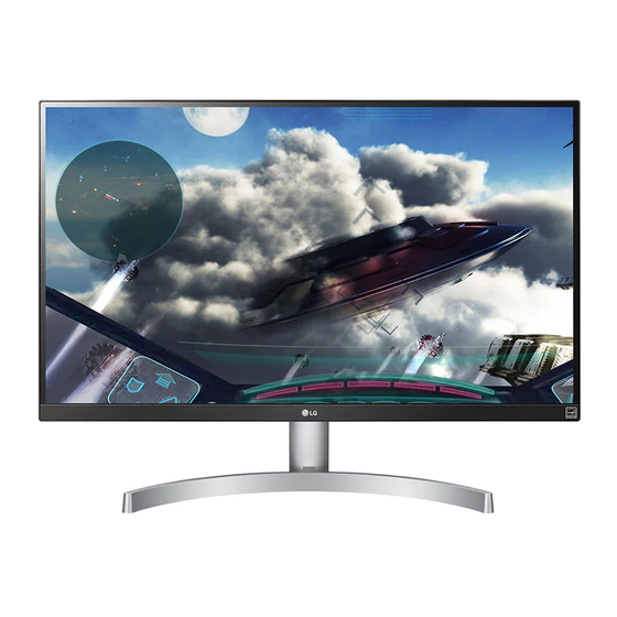
Summary of Contents for LG 27UL600
- Page 1 Internal Use Only LED MONITOR SERVICE MANUAL SERVICE MANUAL CHASSIS : LM8CA MODEL : 27UL600 CAUTION BEFORE SERVICING THE CHASSIS, READ THE SAFETY PRECAUTIONS IN THIS MANUAL. P/NO : MFL69406853(1810-REV00)
-
Page 2: Safety Precautions
SAFETY PRECAUTIONS IMPORTANT SAFETY NOTICE Many electrical and mechanical parts in this chassis have special safety-related characteristics. These parts are identified by in the Schematic Diagram and Exploded View. It is essential that these special safety parts should be replaced with the same components as recommended in this manual to prevent Shock, Fire, or other Hazards. -
Page 3: General Specification
SPECIFICATION NOTE : Specifications and others are subject to change without notice for improvement. 1. General Specification 1) 27UL650 / 27BL65U / 27UL600 * Provided accessory: #8/#9 , it’s different marketing request. Item Content Measurement Result Remark Customer BRAND Checked... - Page 4 2. Signal Timing (Resolution) 2.1. Signal (Video & Sync) V i d e o S y n c 6.1.1 Signal (Video & Sync) – DisplayPort/USB-C Frequency Total Display Front Sync. Back Mode section polarity CLOCK Resolution Measurement Result Remark [kHz]/[Hz] Period(E) Porch(D) Porch(B)
- Page 5 6.1.2 Signal (Video & Sync) – HDMI Frequency Total Display Front Sync. Back Mode section polarity DOT CLOCK[MHz] Resolution Measurement Result Remark [kHz]/[Hz] Period(E) Porch(D) Porch(B) H(Pixels) 31.469 Checked PC : Display 25.175 640 x 480 V(Lines) 59.94 Resolution H(Pixels) 37.879 1056 Checked...
-
Page 6: Block Diagram
BLOCK DIAGRAM... -
Page 7: Exploded View
EXPLODED VIEW IMPORTANT SAFETY NOTICE Many electrical and mechanical parts in this chassis have special safety-related characteristics. These parts are identified by in the Schematic Diagram and EXPLODED VIEW. It is essential that these special safety parts should be replaced with the same components as recommended in this manual to prevent Shock, Fire, or other Hazards. -
Page 8: Assembly And Disassembly
Assembly & Disassembly ■ Disassembly method Fig.1 Place the monitor’s screen face down on a soft cloth. Fig.2 Disassemble the Stand Base with disassemble the screw. Fig 3 disassemble the top cover... - Page 9 Fig 4 Remove the screw(2EA) and disassemble stand body. Fig 5 Remove the Screw(1EA) and disassemble the back cover...
- Page 10 Fig.6 Remove the tape and cable and speaker and control PCB assy Fig.7 Remove the screw (3ea) and disassemble the rear shiled assy Fig.8 Remove the screw (9ea) and disassemble the Cabinet...
-
Page 11: Troubleshooting Guide
TROUBLESHOOTING GUIDE 1. NO POWER Check JP400,JP401 Check Power connector Replace Adapter OK ? Voltage Level (19V) Replace IC601 & Check IC601 Output Recheck Voltage Level (+3.3V) Replace IC405,IC403, IC404 Check IC405,IC403, IC404Output &Recheck Voltage Level (5V,1.8V, 1.15V) Check X200 Clock 12MHz Replace X200 Replace IC202 Flash Memory... - Page 12 2. NO SCREEN ON Check IC 601 Check WLED_ENABLE High? Module Back Light On? Replace Main Scaler IC (IC601 Pin #27) Check Panel Power Replace IC402 & 10V(JP209) Recheck Check e-DP Cable for Replace Cable Damage or Open Conductors Replace T-Con Board or Module...
- Page 13 3. No Video-HDMI Check signal format and resolution Is it supported? Check HDMI Cable for Damage or Open Connector Check JK100 or JK101 for Replace Connector proper connection or Damage Check HDMI 5V from Source(PC) Re Download EDID Data (JK100 and JK101) (Pin No.
- Page 14 4. No Video-DP Check signal format and resolution Is it supported? Check DP Cable for Damage or Open Connector Check JK801 for proper Replace Connector connection or Damage Check AUX Signal (R137 or R142) Replace Main Scaler (IC200)
- Page 15 4. No USB-C Check input signal format Is it supported? Check USB-CCable for Damage or Open Connector Check JK801 for proper Replace Connector connection or Damage Check AUX Signal ReplaceIC801 (R876 or R890) Replace Main Scaler (IC200)
- Page 16 5. No Sound(H/P) Check the Input source. Check Cable status for Damaged or Open Connector Check the sound setting in Setting like a right image. Do re-soldering Check JK501 Soldering Replace Main Scaler (IC200)
- Page 17 6. No Sound(Speaker) Check the Input source. Check Cable for Damaged or Open Connector Check Speaker Cable is Connect the Cable connected correctly Replace Main Scaler Replace Speaker and (IC200) Check the status...


Need help?
Do you have a question about the 27UL600 and is the answer not in the manual?
Questions and answers