Table of Contents
Advertisement
Quick Links
Advertisement
Table of Contents

Related Manuals for Radwin Transportation FiberinMotion


Summary of Contents for Radwin Transportation FiberinMotion
- Page 1 INSTALLATION GUIDE Rev. 0.9 TRANSPORTATION FIBERINMOTION Rel. 4.5.25...
-
Page 2: Table Of Contents
Table of Contents Chapter 1: Introduction 1.1 Scope of this Document ...................... 1‐1 1.2 Transportation FiberinMotion Overview ................1‐1 1.2.1 Major Components...................... 1‐4 TBS ........................1‐4 TBS antennas..................... 1‐4 TMU ........................1‐5 TMU antennas....................1‐6 ISU ........................1‐6 OSU ........................1‐7 GSU ........................1‐8 1.2.2 Accessories ........................1‐8 Lightning Protection Unit (LPU) ................1‐8 PoE ........................ - Page 3 TMU Mounting on a Shelf.................. 2‐34 TMU Mounting on a Wall................... 2‐35 TMU Mounting Using the TMU-PoE Drawer............2‐36 2.3.3 PoE for the TMU ......................2‐45 Mounting on a DIN rail ..................2‐45 2.3.4 TMU Antennas ......................2‐46 TMU - TBS antenna alternative orientation options ..........2‐47 2.3.5 TMU External Connections ..................
- Page 4 List of Figures 1‐1 F O .................. 1‐2 IGURE IBERIN OTION VERVIEW 1‐2 F O ‐ I O ‐ .......... 1‐3 IGURE IBERIN OTION VERVIEW NTERNAL BOARD VIEW 1‐3 TBS ......................1‐4 IGURE UNIT 1‐4 TBS ..................... 1‐4 IGURE ANTENNA 1‐5 TMU ....................... 1‐5 IGURE RADIO 1‐6 S ‐...
- Page 5 2‐36 A M K C ..............2‐17 IGURE NTENNA OUNTING ONTENTS 2‐37 C P C R H ............2‐18 IGURE ONNECT LAMP ADIO OLDER 2‐38 T ....................2‐18 IGURE IGHTEN BOLTS 2‐39 R C ..............2‐18 IGURE OTATE LAMP TIGHTEN BOLTS 2‐40 M...
- Page 6 2‐86 A P E DIN ..............2‐46 IGURE TTACHING RACK 2‐87 “S ‐F ” ‐ ..........2‐47 IGURE HARK ANTENNA BOTTOM VIEWS 2‐88 TMU .......... 2‐47 IGURE ANTENNA MOUNTING CONFIGURATION ROOF 2‐89 A O O ..............
-
Page 7: Chapter 1: Introduction
Chapter 1: Introduction 1.1 Scope of this Document This document shows how to install RADWIN’s Transportation FiberinMotion (FiberinMotion or FinM) solution. This publication is addressed primarily to installing technicians. • For guidelines of the Transportation FiberinMotion network, see the FinM Network Guidelines. • For a description of how to configure and operate the Transportation FiberinMotion solution, see the FinM Configuration Guide 1.2 Transportation FiberinMotion Overview Transportation FiberinMotion is a train‐to‐wayside communications solution that ensures continuous high‐speed wireless connectivity between the rolling stock, the tracks and control center. The Transportation FiberinMotion system consists of powerful base stations deployed along the tracks that connect to mobile units installed onboard the rolling stock. The solution operates in challenging outdoor conditions and underground tunnels. FinM Installation Guide Rev. 0.9 Release 4.5.25 1‐1... -
Page 8: Figure 1-1 Fiberin Motiono
Transportation FiberinMotion Overview Introduction (D,F,G) to power source (B,C) to backhaul network, ISUs/OSUs Figure 1‐1: FiberinMotion Overview The FiberinMotion solution works as follows: A. TBS (Transportation Base Station) units are installed on poles or walls, and are equipped with antennas (usually 4). B. The TBS units are connected to the backhaul network (Gigabit ethernet via RJ45 or fiber optic) and power, C. All TBS units are synchronized to the same clock source. FinM Installation Guide Rev. 0.9 Release 4.5.25 1‐2... -
Page 9: Figure 1-2 Fiberin Motiono
Transportation FiberinMotion Overview Introduction D. TMUs (Transportation Mobile Units) are installed on board rolling stock, and are equipped with antennas (usually 3, installed on the roof). One TMU is installed in the front and another in the rear most compartment of the train. E. The TBS units transmit to/receive from TMUs that are located within its beam. F. The TMU radios are powered by PoE devices or are powered directly by an on‐board switch that can provide PoE‐plus (802.3.at) connection. G. The TMU radios are connected to an on‐board network (recommended speed 1Gbps), which enables connectivity between the two TMUs, as well as connection to other on‐board devices. PoE for TMU Router TMU antenna (one shown) PoE for TMU On‐board ethernet Figure 1‐2: FiberinMotion Overview ‐ Internal On‐board view FinM Installation Guide Rev. 0.9 Release 4.5.25 1‐3... -
Page 10: Major Components
Major Components Introduction 1.2.1 Major Components The major components of the Transportation FiberinMotion solution are described below: TBS (transportation base station) radios are OFDM/MIMO3x3, IP‐67 compliant outdoor units placed at fixed locations along the wayside and communicate with TMUs (Transportation Mobile Units) installed on board trains/metros so as to ensure consistent and reliable broadband radio coverage. Each TBS is connected to an Ethernet switch, which is connected in turn to the wired backhaul network. The TBSs are synchronized to a common time base to avoid potential mutual radio interferences and allow fast handover. 250 mm 280 mm Antenna PoE SFP connections 75 mm Figure 1‐3: TBS unit TBS antennas Although there are many different types of antennas (see Appendix A, Antenna Guidelines for a list of antennas), we recommend using flat dual polarization and single polarization antennas per each direction. This allows a total of 6 RF chains to be connected, while minimizing the number of antennas. Figure 1‐4: TBS antenna FinM Installation Guide Rev. 0.9 Release 4.5.25 1‐4... -
Page 11: Tmu
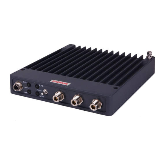
Major Components Introduction TMU TMU (transportation mobile unit) radios operate on‐board, and transmit to/receive from TBSs installed on wayside poles or walls to provide communication connections for on‐board equipment such as routers and WiFi devices. Two TMUs (best practice) are installed on the train (one at each end), are connected to the train internal network, and maintain continuous communications link with the relevant TBS. The TMU to TBS connection establishes an Ethernet broadband network between the train and the core network, which can be used for Uplink/Downlink based services. 230 mm 275 mm Antenna (RF) connections 40 mm Figure 1‐5: TMU radio FinM Installation Guide Rev. 0.9 Release 4.5.25 1‐5... -
Page 12: Tmu Antennas
Major Components Introduction TMU antennas Each TMU is connected to 3 shark‐fin antennas installed on the train roof pointing to the driving direction (see Appendix A, Antenna Guidelines for a list of antennas) : Figure 1‐6: Shark‐fin antenna for Shark‐fin antennas installed on train The ISU (Indoor Synchronization Unit) provides a master clock to all TBSs, and is connected to one of the wayside network switches. Figure 1‐7: Indoor Synchronization Unit FinM Installation Guide Rev. 0.9 Release 4.5.25 1‐6... -
Page 13: Osu
Major Components Introduction OSUs (Outdoor Synchronization Unit), encased in a similar form factor as the TBSs, are outdoor devices that receive a GPS clock signal and distributes this over the wayside network. The OSUs are connected to one of the wayside network switches. If there is a GPS failure, the OSUs act as an ISU and provide the internal clock to the TBSs. Figure 1‐8: Outdoor Synchronization Unit FinM Installation Guide Rev. 0.9 Release 4.5.25 1‐7... -
Page 14: Gsu
Accessories Introduction GSUs (GPS Synchronization Unit) are outdoor devices that receive a GPS clock signal and distributes this over the wayside network. Figure 1‐9: GPS Synchronization Unit 1.2.2 Accessories You will also need some of the following accessories: • Lightning protector unit ‐ for use with outdoor products • CAT‐6 cables ‐ various lengths for use with radios and PoE devices • Grounding cables • Additional mounting kits for the antennas and PoEs ‐ each antenna and each external PoE installed on a pole needs a mounting kit. Lightning Protection Unit (LPU) RADWIN recommends using LPUs when installing outdoor products. Figure 1‐10: Lightning Protection Unit (LPU) FinM Installation Guide Rev. 0.9 Release 4.5.25 1‐8... -
Page 15: Poe
Synchronization Introduction Power‐over‐Ethernet devices can be used to supply both power and network communications to the TBS, TMU, and the OSU/ISU/GSUs. RADWIN provides different types of AC/DC PoE injectors in several power ranges. If M12 cabling must be used on board, a special PoE‐TMU cable is available from RADWIN. PoE for the TMU Outdoor PoE Indoor PoE (ruggedized, with M12 connections) Figure 1‐11: PoE Units Alternatively RADWIN TBS/TMU/OSU can be connected directly to a standard 802.3at (PoE+) device. It is always advised to consult with RADWIN professional services for the best power solution for your project. 1.2.3 Synchronization • The TBS's network is synchronized either via GPS‐based system (for above ground sce‐ narios) or via Ethernet‐based synchronization (for above or underground scenarios). • For GPS based synchronization, the TBS’s integrated GPS Synchronization Unit is used. If this is not possible, the GSU can be used. • Ethernet‐based synchronization runs over the same data backhaul network. The imple‐ mentation of the synchronization protocol is via an Indoor Synchronization Unit (ISU) or Outdoor Synchronization Unit (OSU) that is connected to one of the network switches, and provides the master clock to all TBSs in the network. • OSU is a fully outdoor unit with an embedded GPS antenna as well as an external GPS antenna port (to be used if an external GPS antenna is needed), and can con‐ nect to the network via fiber optic. • The OSU and ISU work in the same manner, with one important difference: The OSU can receive a GPS signal as the synchronization source. • Using multiple OSUs enables synchronization of a ring topology, each OSU synchro‐ nizing a section of the ring. • Redundant synchronization units ensure higher resiliency of the solution. -
Page 16: Features
Frequency bands ‐ 4.9‐5.9GHz (as local regulations permit) » Dedicated Bandwidth ensuring SLA & latency » Low and constant latency – min < 3ms, typical 4ms » Channel bandwidth – 20/40/80 MHz » Regulations supported ‐ FCC/IC/ETSI/WPC/MII/Universal/Japanese/Thai Regulations » Robust, reliable and can operate in harsh environments 1.3.2 Mobility Capabilities » Fast handover ‐ less than 50msec » Up to 750 Mbps per TBS » High speed ‐ up to 300 Kph / 186 Mph » Up to 16 TMUs per TBS » RADWIN Network Management System support » Smart Bandwidth Management (SBM) using dynamic bandwidth allocation to maxi‐ mize service provider throughput and adhere to customer SLAs 1.3.3 Onboard Mobile Units » Up to 750 Mbps aggregate throughput per TMU » Supports customer SLAs by assignment of dedicated bandwidth for uplink and down‐ link per TMU, at the TBS » Separate uplink and downlink configurable Maximum Information Rate (MIR) per 1.4 Document Notifications Notifications consist of Warnings, Cautions and Notes. Warning: risk of danger to persons. FinM Installation Guide Rev. 0.9 Release 4.5.25 1‐10... - Page 17 Document Notifications Introduction Caution: risk of damage to equipment or of service degradation • Provide additional background • Offer a recommendation • Remind you of something that should be kept in mind FinM Installation Guide Rev. 0.9 Release 4.5.25 1‐11...
-
Page 18: Chapter 2: Site Installation
Chapter 2: Site Installation 2.1 Scope of This Chapter This chapter describes how to install the equipment for the Transportation FiberinMotion solution. It is divided into two main sections: • Wayside installation • On‐board installation 2.2 Wayside The FiberinMotion solution uses multiple antennas to enable MIMO and Diversity modes. The solution relies on antenna spacing, as well as dual polarization / dual slanted antennas to differentiate the radio streams. 2.2.1 Overview General Mounting Arrangement The TBS unit must be installed in a Restricted Access Location. The TBS can be mounted on a pole or a wall, together with its antennas and LPUs. To enable better MIMO conditions, the antennas should be divided between vertical and horizontal polarizations. Figure 2‐1 shows an example of a TBS mounted on a pole • Place the tower/TBS at the location determined by the site survey. • Make sure there is sufficient line‐of‐sight towards the track segment the antennas will cover • Make sure that there are no obstacles directly in front of the antennas • The lowest antenna must be higher than the highest rail car on the line • There are several ways you can orient the TBS antennas, depending on the orien‐ tation of the TMU antennas. These options are detailed in see TMU ‐ TBS antenna alternative orientation options on page 2‐47. FinM Installation Guide Release 4.5.25 2‐1... - Page 19 Overview Site Installation Figure 2‐1: TBS ‐ Base Station mounting with antennas (outside) FinM Installation Guide Release 4.5.25 2‐2...
-
Page 20: Power
Overview Site Installation Figure 2‐2: TBS ‐ Base Station mounting with antennas (tunnel) Lowest antenna Highest railcar Figure 2‐3: TBS antennas ‐ lowest antennas higher than the highest rail car Power • Use the PoE to supply power to the TBS • Use the PoE or the SFP fiber connection to provide a LAN connection to the TBS. • Install two Lightning Protection Units (LPU): One close to the TBS, and the other close to the PoE. Minimum Recommended Distances There are two antennas for each direction (see Figure 2‐1). Recommended vertical separation between each antenna is 1.0m. FinM Installation Guide Release 4.5.25 2‐3... -
Page 21: Tbs Mounting
TBS Mounting Site Installation 2.2.2 TBS Mounting The TBS can be mounted on a vertical or horizontal pole, or on a wall. • Vertical pole: see page 2‐6 for directions relevant to all sizes. • Thin pole: see page 2‐6. • Medium pole: see page 2‐8 • Thick pole: see page 2‐8 • Horizontal pole: see page 2‐9 for directions relevant to all sizes. • Thin pole: see page 2‐11. • Medium pole: see page 2‐12 • Thick pole: see page 2‐13 • Wall: The TBS can be mounted on a wall, see page 2‐13. Check the package contents: Figure 2‐4: TBS mounting kit package contents Table 2‐1: TBS mounting kit package contents Item Description Quantity Base plate Pole clamp Hex screw with flange M8x90 FinM Installation Guide Release 4.5.25 2‐4... - Page 22 TBS Mounting Site Installation Table 2‐1: TBS mounting kit package contents (Continued) Item Description Quantity Standoffs M4x16 Allen screws M4x30 Washers for allen screws FinM Installation Guide Release 4.5.25 2‐5...
-
Page 23: Tbs Mounting On A Vertical Pole
TBS Mounting Site Installation TBS Mounting on a Vertical Pole All sizes 1. Fasten the standoffs to the base plate in the holes labeled “V” as shown: Figure 2‐5: Fasten standoffs to base plate (for vertical pole) 2. Place the TBS as shown over the standoffs, and using the Allen screws and washers, fasten the TBS to the base plate. Figure 2‐6: Fasten TBS to base plate (for vertical pole) Vertical Pole ‐ thin 1. Diameter 3/4 to 1 1/2: Before raising the TBS on the pole, position the pole clamp as shown in the following two figures. Do not completely tighten the bolts: FinM Installation Guide Release 4.5.25 2‐6... -
Page 24: Figure 2-7 Thin Pole : Fasten
TBS Mounting Site Installation Thin pole (diameter 3/4 to 1 1/2): Position the pole clamp as shown in the following two figures, do not completely tighten the bolts: Figure 2‐7: Thin pole: Fasten clamp to base Figure 2‐8: Thin pole: Do not completely plate tighten bolts 2. Place this assembly on the pole where you want to mount the TBS. Once it is in place, rotate the pole clamp as shown, then tighten both bolts. Figure 2‐9: Thin pole: Rotate clamp Figure 2‐10: Thin pole: tighten bolts FinM Installation Guide Release 4.5.25 2‐7... -
Page 25: Figure 2-11 Medium Pole : F
TBS Mounting Site Installation Vertical pole ‐ medium 1. Diameter 2 to 3: Before raising the TBS on the pole, position the pole clamp as shown in the following two figures. Do not completely tighten the bolts: Figure 2‐11: Medium pole: Fasten clamp to Figure 2‐12: Medium pole: Do not com‐ base plate pletely tighten bolts 2. Place this assembly on the pole where you want to mount the TBS. Once it is in place, rotate the pole clamp as shown, then tighten both bolts. Figure 2‐13: Medium pole: Rotate clamp Figure 2‐14: Medium pole: tighten bolts Vertical Pole ‐ thick 1. Diameter larger than 3: Use worm drive clamps (not supplied), threaded through the holes as shown in Figure 2‐15, or U‐bolts (not supplied), fastened using the holes as shown in Figure 2‐16: FinM Installation Guide Release 4.5.25 2‐8... -
Page 26: Tbs Mounting On A Horizontal Pole
TBS Mounting Site Installation Figure 2‐15: Using worm drive clamps for a thick pole Figure 2‐16: Using U‐bolts for a thick pole TBS Mounting on a Horizontal Pole All sizes Before fastening the TBS to the base plate (see Step 1. on page 2‐6), rotate the plate by 90 clockwise. Make sure the arrow next to the “H” points up. FinM Installation Guide Release 4.5.25 2‐9... -
Page 27: Figure 2-18 Fasten Standoffs
TBS Mounting Site Installation Figure 2‐17: Rotate base plate clockwise 90 for horizontal pole 2. Fasten the standoffs to the base plate in the holes labeled “H” as shown: Figure 2‐18: Fasten standoffs to base plate (for horizontal pole) 3. Place the TBS as shown over the standoffs, and using the Allen screws and washers, fasten the TBS to the base plate. FinM Installation Guide Release 4.5.25 2‐10... -
Page 28: Figure 2-19 Fasten Tbs To
TBS Mounting Site Installation Figure 2‐19: Fasten TBS to base plate (for horizontal pole) Horiztonal Pole ‐ thin 1. Diameter 3/4 to 1 1/2: Before raising the TBS on the pole, position the pole clamp as shown in the following two figures. Do not completely tighten the bolts: Thin pole (diameter 3/4 to 1 1/2): Position the pole clamp as shown in the following two figures, do not completely tighten the bolts: Figure 2‐20: Thin pole: Fasten clamp to base Figure 2‐21: Thin pole: Do not completely plate tighten bolts FinM Installation Guide Release 4.5.25 2‐11... -
Page 29: Figure 2-22 Thin Pole : Rotate
TBS Mounting Site Installation 2. Place this assembly on the pole where you want to mount the TBS. Once it is in place, rotate the pole clamp as shown, then tighten both bolts. Figure 2‐22: Thin pole: Rotate clamp Figure 2‐23: Thin pole: tighten bolts Horizontal Pole ‐ medium 1. Diameter 2 to 3: Before raising the TBS on the pole, position the pole clamp as shown in the following two figures. Do not completely tighten the bolts: Figure 2‐24: Medium pole: Fasten clamp to Figure 2‐25: Medium pole: Do not com‐ base plate pletely tighten bolts FinM Installation Guide Release 4.5.25 2‐12... -
Page 30: Tbs Mounting On A Wall
TBS Mounting Site Installation 2. Place this assembly on the pole where you want to mount the TBS. Once it is in place, rotate the pole clamp as shown, then tighten both bolts. Figure 2‐26: Medium pole: Rotate clamp Figure 2‐27: Medium pole: tighten bolts Horiztonal Pole ‐ thick 1. Diameter larger than 3: Use metal bands (not supplied), threaded through the holes as shown in Figure 2‐28, or U‐bolts (not supplied), fastened using the holes as shown in Figure 2‐29: Figure 2‐28: Using metal bands for a large poleFigure 2‐29: Using U‐bolts for a large pole TBS mounting on a wall 1. Fasten the standoffs to the base plate in the holes labeled “V” or “H”, whichever is more convenient, as shown: FinM Installation Guide Release 4.5.25 2‐13... -
Page 31: Figure 2-30 Fasten Standoffs
TBS Mounting Site Installation <‐> Figure 2‐30: Fasten standoffs to base plate Figure 2‐31: Standoffs fastened to base plate 2. Use anchor bolts to attach base plate to a wall, as shown: FinM Installation Guide Release 4.5.25 2‐14... -
Page 32: Figure 2-32 Attach Base Plate
TBS Mounting Site Installation Attach the base plate to a wall using 9mm dia. anchor bolts (not supplied) in the holes indicated. Figure 2‐32: Attach base plate to wall 3. Place the TBS as shown over the standoffs, and using the Allen screws and washers, fasten the TBS to the base plate. Figure 2‐33: Fasten TBS to base plate on wall FinM Installation Guide Release 4.5.25 2‐15... -
Page 33: Poe Devices For The Tbs
PoE Devices for the TBS Site Installation Figure 2‐34: TBS mounted on a wall Always mount a TBS with the connectors on the bottom. Never mount a unit horizontally. 2.2.3 PoE Devices for the TBS The TBS is powered by a PoE device, installed in a cabinet. Figure 2‐35: PoE external connections FinM Installation Guide Release 4.5.25 2‐16... -
Page 34: Tbs Antennas
TBS Antennas Site Installation 2.2.4 TBS Antennas Use the antenna mounting kit (different from the TBS mounting kit) to mount a TBS antenna on a pole or wall. . • Vertical pole: see page 2‐18 to • Thin pole: see page 2‐17. • Medium pole: see page 2‐18 • Thick pole: see page 2‐20 • Horizontal pole: see page 2‐20 for directions relevant to all sizes. • Wall: see page 2‐21. Figure 2‐36: Antenna Mounting Kit Contents Tighten all bolts with a torque of 15Nm. TBS Antenna Mounting on a Vertical Pole Thin Pole This method is for mounting the TBS antenna on a pole of pipe size 3/4 to 1 1/2 in. FinM Installation Guide Release 4.5.25 2‐17... -
Page 35: Figure 2-37 Connect Polec
TBS Antennas Site Installation Do not mount the TBS antenna on a pole smaller than 3/4 in. 1. When mounting on a thin pole, position the pole clamp as shown in the following figures: Figure 2‐37: Connect Pole Clamp to Radio Figure 2‐38: Tighten bolts Holder 2. Place this “unit” on the pole where you want to mount the antenna. Once it is in place, rotate the pole clamp as shown, then tighten both bolts. Figure 2‐39: Rotate Clamp and tighten bolts Figure 2‐40: Mounting Kit on thin pole Medium Pole This method is for mounting the TBS antenna on a pole of pipe size 2 to 3 in. 3. Connect the pole clamp to the radio holder with the 8x90 bolts, but do not tighten the bolts all the way ‐ tighten them so that they are not closer than a distance FinM Installation Guide Release 4.5.25 2‐18... -
Page 36: Figure 2-41 Connect Polec
TBS Antennas Site Installation equal to the radius of the pole. You will then have one “unit” that you can take to the location on the pole where you want to mount the antenna. (See Figure 2‐37 to Figure 2‐40 for mounting on a thin pole) Figure 2‐41: Connect Pole Clamp to Radio Figure 2‐42: Tighten bolts Holder 4. Place this “unit” on the pole where you want to mount the antenna. Once it is in place, rotate the pole clamp as shown, then tighten both bolts. Figure 2‐43: Rotate Clamp and tighten bolts Figure 2‐44: Mounting Kit on pole Thick Pole • This method is for mounting the TBS antenna on a pole of pipe size larger than 3 in. • Use worm drive clamps (not supplied), threaded through the holes as shown. The pole clamp is not needed. FinM Installation Guide Release 4.5.25 2‐19... -
Page 37: Figure 2-45 Mounting Kit On
TBS Antennas Site Installation Figure 2‐45: Mounting kit on a thick pole TBS Antenna Mounting on a Horizontal Pole When using the mounting kit on a horizontal pole, use the radio vertical adaptor, as shown: Figure 2‐46: Mounting kit on a horizontal pole FinM Installation Guide Release 4.5.25 2‐20... -
Page 38: Figure 2-47 Flat Panel Antenna
TBS Antennas Site Installation TBS Antenna Mounting on a Wall When using the mounting kit on a wall, the pole clamp is not necessary: TBS Antenna Mounting Kit Adaptor The mounting kit adaptor appears as shown in Figure 2‐47: Figure 2‐47: Flat panel antenna mounting kit adapter A flat panel antenna such as that shown in Figure 2‐49 is typically used. It has eight bolts for a mounting kit adapter, which allows you to mount the antenna in a straight up‐and‐down manner, or in a diagonal manner. FinM Installation Guide Release 4.5.25 2‐21... -
Page 39: Figure 2-48 Flat Panela
TBS Antennas Site Installation Typically, the upper antenna is mounted diagonally, an has both a Vertical and Horizontal polarization. The lower antenna is mounted straight, with only a Vertical polarization. See also Figure 2‐1, "TBS ‐ Base Station mounting with antennas (outside)". Attach the mounting kit adaptor to the rear of the antenna as shown: Flat antenna Mounting Kit Flat antenna Mounting Kit rear view) Adaptor rear view) Adaptor Figure 2‐48: Flat Panel Antenna ‐ straight Figure 2‐49: Flat Panel Antenna ‐ diagonal mount mount Figure shows a mounted antenna. Fasten the mounting nut to the side of the adaptor with the recess, as shown. FinM Installation Guide Release 4.5.25 2‐22... - Page 40 TBS Antennas Site Installation Flat antenna Mounting Kit (rear view) Adaptor Nut fastened in recess Figure 2‐50: Flat Panel antenna ‐ straight‐mounted on a pole Mounting Kit Flat antenna Adaptor (rear view) Nut fastened in recess Figure 2‐51: Flat Panel antenna ‐ diagonal‐mounted on a pole FinM Installation Guide Release 4.5.25 2‐23...
-
Page 41: Figure 2-52 Tbs External
TBS External Connections Site Installation 2.2.5 TBS External Connections Figure 2‐52: TBS external connections The “A” direction relates to the direction this set (the “A” set) of antennas are pointing, and the “B” direction relates to the direction the “B” set of antennas are pointing. Which direction is A and which is B is arbitrary. Table 2‐2: TBS LED Indicators (PoE port) LED LED Location On Blinking Color Power is being Yellow No power N.A. supplied Yellow Green No LAN A LAN connection Data is flowing connection Green exists, but no data via the LAN is flowing connection No power TBS LEDs shut off after 5 minutes of operation. FinM Installation Guide Release 4.5.25 2‐24... -
Page 42: Figure 2-53 Indoors
Synchronization Units Site Installation 2.2.6 Synchronization Units Indoor Synchronization Unit (ISU) The Indoor Synchronization Unit (ISU) provides a master synchronization clock for all TBS units, and is connected to one of the network switches. It can be installed on a 19in. rack or on a convenient indoor surface. Figure 2‐53: Indoor Synchronization Unit (ISU) FinM Installation Guide Release 4.5.25 2‐25... -
Page 43: Figure 2-54 Osu External
Synchronization Units Site Installation Outdoor Synchronization Unit (OSU) The Outdoor Synchronization Unit (OSU) provides a master synchronization clock for all TBS units, and is connected to one of the network switches. It is housed in the same housing as a TBS unit, and is installed in the same manner as a TBS (see TBS Mounting on page 2‐4). It receives a GPS synchronization signal, and can use its integrated GPS antenna, or an external GPS antenna. Antenna (RF) connections are not used Figure 2‐54: OSU external connections Table 2‐3: OSU LED Indicators (PoE port) LED LED Location On Blinking Color GPS Internal Yellow No power Yellow Green synchronization synchronization A LAN connection exists, but no data is flowing No LAN Data is flowing via Green connection or the LAN OSU LEDs shut No power connection off after 5 minutes of operation. -
Page 44: Figure 2-55 Mounted Gsu S
Synchronization Units Site Installation GSUs (GPS Synchronization Unit) are outdoor devices that receive a GPS clock signal and distributes this over the wayside network. A GSU is mounted in the same manner as TBS external antennas (see TBS Antennas on page 2‐17), and can be mounted on a vertical or horizontal pole, or a wall. Vertical pole Horizontal pole Wall Figure 2‐55: Mounted GSUs The external connections of the GSU are shown in Figure 2‐56, below. Connect the external GPS antenna to the antenna port (labeled “GPS” on the unit), and a PoE unit with both ethernet and power to the “IDU” port. The “Sync” port is used when working with an external Hub Site Synchronization unit (HSS unit), which is not usually relevant for FinM projects. Figure 2‐56: GSU External connections FinM Installation Guide Release 4.5.25 2‐27... -
Page 45: Figure 2-57 Gps Antenna And Figure 2-58 Lightningp
External GPS Antenna Site Installation 2.2.7 External GPS Antenna The external GPS antenna is mounted on a vertical or horizontal pole segment. The QMA connector connects the antenna to the TBS/OSU external GPS port. Although the TBS/OSU has an integrated GPS antenna, in some cases, it might be necessary to locate a GPS antenna in a different location. In that case, this GPS antenna can be used. Each installation should be evaluated by RADWIN professional services personnel. Figure 2‐57 shows the GPS antenna on its mount. The antenna is seated in an inverted L plate with a hole for the antenna port. The L plate is strapped to the pole with a pair of worm drive clamps. Figure 2‐57: GPS antenna and mount FinM Installation Guide Release 4.5.25 2‐28... -
Page 46: Figure 2-59 Basic Use Of
Lightning Protection Unit (LPU) Site Installation 2.2.8 Lightning Protection Unit (LPU) The use of lightning protection is dependent on regulatory and end user requirements. Although FiberinMotion units have surge limiting circuits that minimize the risk of damage due to lightning strikes, RADWIN recommends the use of additional surge arrestor devices to protect the equipment from nearby lightning strikes. Figure 2‐58: Lightning Protection Unit (LPU) For any type of indoor unit‐outdoor unit connection, the LPUs are installed in pairs, as shown in Figure 2‐59: Figure 2‐59: Basic use of lightning protector units FinM Installation Guide Release 4.5.25 2‐29... -
Page 47: Figure 2-62 Lpu Attached To
Lightning Protection Unit (LPU) Site Installation The LPU has two cable glands on the bottom for CAT‐5e/6 cables, in addition to a grounding lug. On the side of the LPU is a slot for the metal tie when installed on a pole, as shown in Figure 2‐60 and Figure 2‐61: Figure 2‐60: LPU: Bottom View Figure 2‐61: LPU: Side View To install an LPU on a pole: 1. Choose a location as close as possible to the radio unit. Insert the metal tie through the slots as shown in Figure 2‐61. Make sure the LPU is oriented in the correct direction, as shown in Figure 2‐62. Figure 2‐62: LPU attached to pole with metal tie 3. Tighten the metal tie. 4. Connect the grounding lug to a grounding source. 5. Remove the cable glands. 6. Thread the CAT‐5e/6 cables through the cable glands, and connect the cables to the LPU as shown in Figure 2‐63. FinM Installation Guide Release 4.5.25 2‐30... -
Page 48: Figure 2-63 Connecting Cables
Lightning Protection Unit (LPU) Site Installation Tighten the cable glands around the CAT‐5e cables as shown in Figure 2‐64. Figure 2‐63: Connecting cables to the LPU (1) Figure 2‐64: Connecting cables to the LPU (2) 8. Route one CAT‐5e/6 up to the radio, and the other down to the IDU or PoE (via the lower LPU). An LPU installed on a pole is shown in Figure 2‐65. 9. RADWIN recommends that you add extra waterproofing to the connections (see see "Waterproofing" on page 2‐32.). Figure 2‐65: Installing an LPU on a pole (side view) FinM Installation Guide Release 4.5.25 2‐31... -
Page 49: Figure 2-66 Exposing The Tacky
Waterproofing Site Installation 2.2.9 Waterproofing Protect all connections between any outdoor devices and cables from rain, dust, moisture and salt according to the procedure below: 1. Use a high quality sealing material such as Scotch 23 Tape ¾” wide, to ensure IP‐67 compliant protection against water and dust. 2. Cut two pieces each 25 cm long, of Scotch 23 splicing tape. Remove the plastic cover to expose the tacky side of the sealing tape as shown in Figure 2‐66. Figure 2‐66: Exposing the tacky side of the sealing tape 3. After connecting a cable to a unit, tighten the cable gland cap firmly and use the insulation tape to fully cover the cable gland. Figure 2‐67: Waterproofing an external connection FinM Installation Guide Release 4.5.25 2‐32... -
Page 50: Figure 2-68 O N - Board General
On‐board Site Installation 2.3 On‐board 2.3.1 Overview The FiberinMotion solution uses shark fin antennas for its mobile units, and relies on antenna orientation to differentiate the radio streams enough so as to enable MIMO. General Guidelines • Locate the antennas on the roof of the locomotive, as close as possible to each end of the locomotive. • Place the TMU as close as possible to the antennas. This will allow a 2m cable to be used to the antennas. Power • Recommended: Use RADWIN’s PoE to supply power to the TMU • Alternative: TMU can be powered via an 802.3at (PoE plus) switch General Mounting Arrangement On‐board TMU Antenna router PoE for Figure 2‐68: On‐board general mounting arrangement FinM Installation Guide Release 4.5.25 2‐33... -
Page 51: Tmu Mounting On A Shelf
TMU Mounting Site Installation Cables to TMU antennas PoE for To on‐board switch TMU‐PoE Cable Power to Figure 2‐69: On‐board general mounting arrangement ‐ detail view 2.3.2 TMU Mounting The TMU can be mounted in a 19 in rack, on a shelf, or on a wall. When mounting on a 19 in rack, use the specially‐designed TMU‐PoE drawer. TMU Mounting on a Shelf The TMU can be placed in any convenient horizontal surface, such as a shelf. Fasten the unit and its PoE properly. Make sure the TMU and PoE are completely on the shelf. FinM Installation Guide Release 4.5.25 2‐34... -
Page 52: Tmu Mounting On A Wall
TMU Mounting Site Installation Power Ethernet To Antennas Figure 2‐70: TMU mounted on a shelf TMU Mounting on a Wall The TMU can be mounted an a wall with proper support. Use the mounting holes and customer‐supplied screws to fasten the unit to a wall. PoE for Figure 2‐71: TMU and PoE mounted on a wall FinM Installation Guide Release 4.5.25 2‐35... -
Page 53: Tmu Mounting Using The Tmu-Poe Drawer
TMU Mounting Site Installation TMU Mounting Using the TMU‐PoE Drawer The TMU‐PoE drawer is used to mount both the TMU and the PoE together. Carry out the following steps to mount both units: 1. Choose a site for the TMU‐PoE drawer as close as possible to the on‐board antennas and on‐board power supply. Make sure there is at least 12 cm (5 in) of rack space. 2. Open the package, remove the TMU‐PoE drawer from the packing styrofoam, and cut and discard the two black straps holding the mounting slides in place. 3. Check the contents: Table 2‐4: TMU‐PoE drawer package contents Item Description Quantity Tray DC‐TMU Jumper cable Allen wrench (M4) Allen screws (M4x22) Spring washers for Allen screws DIN screws (M5x16) Black finishing washers for M5 screws Mechanical cage/nuts for M5 screws FinM Installation Guide Release 4.5.25 2‐36... - Page 54 TMU Mounting Site Installation Figure 2‐72: TMU‐PoE drawer contents FinM Installation Guide Release 4.5.25 2‐37...
-
Page 55: Figure 2-73 Remove The Figure 2-74 Measure Distance
TMU Mounting Site Installation 4. Detach the mounting slides from the TMU‐PoE drawer: Pull each slide out until it is stopped by the locking lever. Press the locking lever to release the slide, and pull slide out completely. Drawer Mounting slide Locking Lever Press Locking Lever to release slide Remove slide Figure 2‐73: Remove the mounting slides from the TMU‐PoE drawer. FinM Installation Guide Release 4.5.25 2‐38... -
Page 56: Figure 2-75 Adjust Distance
TMU Mounting Site Installation 5. Measure the distance between vertical rails of the rack. Figure 2‐74: Measure distance between vertical rails 6. Adjust the location of the rear mounting flange of the first mounting slide so that the distance between the holes of the mounting flanges are the same as the distance you measured in the previous step. Figure 2‐75: Adjust distance of rear mounting flange FinM Installation Guide Release 4.5.25 2‐39... -
Page 57: Figure 2-76 Adjust Distance
TMU Mounting Site Installation 7. Place the second slide next to the first and adjust its rear mounting flange so that the distance between the flanges are the same as that of the first slide. Figure 2‐76: Adjust distance of mounting flange on second slide 8. Insert 8 mechanical cage nuts in the appropriate holes in the 19 in rack: 4 on each side of the rack. Figure 2‐77: Inserting cage nuts (one side shown) FinM Installation Guide Release 4.5.25 2‐40... -
Page 58: Figure 2-78 Placing And Figure 2-79 Inserting The
TMU Mounting Site Installation 9. Place each mounting slide with the stopping flap towards the rear of the rack, and using the Philips screws with the black washers, fasten the mounting slides to the cage nuts and tighten. Figure 2‐78: Placing and fastening mounting slide 10.Once both mounting slides are fastened tightly on the rack, insert the drawer as follows: a. Place the framework arms of the drawer into the mounting slides carefully. Make sure they are straight. b. Push back the drawer until the framework arms touch the ball‐bearing grey housing. c. While pressing outwards on both ball‐bearing grey housings, push the drawer in further until the framework arms engage the ball‐bearing housings. d. Further push the drawer until the locking lever stops it. e. Release the locking levers, and push the drawer in all the way, even through some resistance towards the end. FinM Installation Guide Release 4.5.25 2‐41... -
Page 59: Figure 2-80 Inserting The Figure 2-81 Inserting The
TMU Mounting Site Installation Figure 2‐79: Inserting the drawer: Place arms straight Push ball‐bearing housing outwards Figure 2‐80: Inserting the drawer: Push ball‐bearing housings outwards FinM Installation Guide Release 4.5.25 2‐42... -
Page 60: Figure 2-82 Secure Drawer To
TMU Mounting Site Installation Press locking levers and push drawer in Figure 2‐81: Inserting the drawer: Release locking levers 11.Insert the other 4 cage nuts in the appropriate holes in the front side of the vertical rails. 12.Using the other 4 Philips screws with the black washers, secure the drawer to the front side of the vertical rails of the rack. Figure 2‐82: Secure drawer to the front side of rack FinM Installation Guide Release 4.5.25 2‐43... -
Page 61: Figure 2-83 Attaching P O Eto
TMU Mounting Site Installation 13.Attach PoE and TMU to drawer as follows: a. Remove grounding lugs from both units (they interfere with the drawer and are not needed for a drawer installation). b. Place PoE over the pins of the left side of the drawer as shown, and attach using hex (Allen) screws. Figure 2‐83: Attaching PoE to drawer FinM Installation Guide Release 4.5.25 2‐44... -
Page 62: Poe For The Tmu
PoE for the TMU Site Installation c. Place TMU over the pins on the right side of the drawer as shown, and attach using hex (Allen) screws. Figure 2‐84: Attaching TMU to drawer The TMU and PoE, when mounted in the TMU‐PoE drawer, are grounded via the mounting pins, through the 19 in rack. Make sure the rack you are using is grounded properly. 2.3.3 PoE for the TMU The units can be mounted in a 19 in rack, a shelf, or on a wall. Mounting with the TMU‐PoE drawer The TMU‐PoE drawer can be used to mount both the TMU and the PoE. Follow the instructions in “TMU Mounting Using the TMU‐PoE Drawer” on page 2‐36. Mounting on a DIN rail Carry out the following steps to mount the PoE on a DIN rail: FinM Installation Guide Release 4.5.25 2‐45... -
Page 63: Tmu Antennas
TMU Antennas Site Installation PoE with DIN rail adaptor Fasten DIN rail adaptor to PoE Figure 2‐85: Attaching a DIN rail adaptor to the PoE PoE opposite DIN rail Place DIN rail onto PoE Insert DIN rail in adaptor Open adaptor lock Close adaptor lock PoE attached to DIN rail Figure 2‐86: Attaching a PoE to a DIN rack 2.3.4 TMU Antennas Each TMU requires three “Shark‐Fin” antennas mounted on the roof of the locomotive as close as possible to the TMU: FinM Installation Guide Release 4.5.25 2‐46... -
Page 64: Tmu - Tbs Antenna Alternative Orientation Options
TMU Antennas Site Installation Figure 2‐87: “Shark‐Fin” antenna ‐ bottom and top views Note the following: • The antennas should be mounted as close to the TMU as possible. • Try to minimize obstructions between the antennas and the front of the train such as air‐conditioner units, electronic route number display boxes and the like. • Mount Antenna 1 and Antenna 2 on the edge of the locomotive at a 45 angle, as shown in Figure 2‐88. Also see TMU ‐ TBS antenna alternative orientation options on page 2‐47 for other possibilities. • Mount Antenna 3 (center) at a 90 angle (directly up) as shown in Figure 2‐88. • Connect the antenna ports of the TMU to the antennas as shown in Figure 2‐90. Figure 2‐88: TMU antenna mounting configuration on roof TMU ‐ TBS antenna alternative orientation options Although Figure 2‐88, "TMU antenna mounting configuration on roof" shows the most common method of mounting the TMU antennas, there are other options, and these are shown here: FinM Installation Guide Release 4.5.25 2‐47... - Page 65 TMU Antennas Site Installation Figure 2‐89: Antenna Orientation Options FinM Installation Guide Release 4.5.25 2‐48...
- Page 66 TMU Antennas Site Installation Figure 2‐90: TMU antenna port connection scheme 4. Connect the RF cable as shown below: Figure 2‐91: Connect RF cable to TMU antenna (on mount) FinM Installation Guide Release 4.5.25 2‐49...
-
Page 67: Tmu External Connections
Site Installation 2.3.5 TMU External Connections Figure 2‐92: TMU ‐ External Connections Table 2‐5: TMU LED Indicators LED LED Location On Blinking Name Power is being No power N.A. supplied No GPS signal or GPS signal is being N.A. received No power A LAN connection Data is flowing No LAN connection or exists, but no data via the LAN No power is flowing connection Active wireless link Searching for a LINK No power exists wireless link 2.4 Grounding All RADWIN products must be grounded during operation. In addition: • All units should be grounded by a wire with diameter of at least 10 AWG by skilled and trained technicians. FinM Installation Guide Release 4.5.25 2‐50... -
Page 68: Tbs And Osu
Grounding Site Installation Units must be properly grounded to a Protective Ground in accordance with the Local Electrical Regulations • Rack‐mounted equipment should be mounted only in grounded racks and cabinets. Further, you should ‐ • Always make the ground connection first and disconnect it last • Never connect telecommunication cables to ungrounded equipment • Ensure that all other cables are disconnected before disconnecting the ground TBS and OSU There is a grounding lug on the TBS and OSU as shown in Figure 2‐93. Ground it using 10 AWG wire. Connect the shield of the antenna coaxial cable to the ground of the structure in accordance with 6.2gand 6.2l of IEC 60728‐11. Figure 2‐93: TBS/OSU: Grounding lug location The grounding lug for the TMU is shown in Figure 2‐94. Ground it using 10 AWG wire. FinM Installation Guide Release 4.5.25 2‐51... -
Page 69: Finm Poe
Grounding Site Installation Figure 2‐94: TMU: Grounding lug location When mounted in a 19 in rack, the TMU is grounded via the rack. FinM PoE There is a grounding lug on the FinM PoE as shown in Figure 2‐95. Ground it using 10 AWG wire. Figure 2‐95: PoE: Grounding lug location When mounted in a 19in rack, the PoE is grounded via the rack. FinM Installation Guide Release 4.5.25 2‐52... -
Page 70: Gsu
Grounding Site Installation There is a grounding lug on the GSU as shown in Figure 2‐97. Ground it using 10 AWG wire. Figure 2‐96: GSU: Grounding lug location External PoE There is a grounding lug on the external PoE as shown in Figure 2‐97. Ground it using 10 AWG wire. Figure 2‐97: PoE: Grounding lug location FinM Installation Guide Release 4.5.25 2‐53... -
Page 71: Isu
Grounding Site Installation The ISU is grounded via its ground connection on its front panel. Figure 2‐98: ISU: Grounding lug location FinM Installation Guide Release 4.5.25 2‐54... -
Page 72: Appendix A: Antenna Guidelines
Appendix A: Antenna Guidelines A.1 For Deployment in USA/Canada The TBS and TMU devices bear the following identifications on their label: Contains FCC ID: Q3K‐5XACMOD3C Contains IC: 5100A‐5XACMD3CN Only the antennas shown in the table below are approved for use in this system. Use of antennas not in the list invalidate regulatory approval and violate the warranty terms of RADWIN, Ltd. The antennas must be installed so as to provide a minimum separation distance from bystanders as specified in the table below: Table A‐1: Approved Antennas ‐ 5725‐5850 MHz Band Min. Safe Gain Tx Power per Cat. No. Type Dir BW Distance (dBi) Chain (cm) Dual Polarization‐ RW‐9105‐5158 19.0 17.0° 12.0 78.0 Directional Vehicular Single‐ RW‐9401‐5002 12.5 50.0° 18.5 37.0 directional Single Polarization‐ AT0058760 18.0 18.0° 13.0 70.0... -
Page 73: A.2 For Deployment In Japan
Table A‐2: Approved Antennas ‐ 5470‐5725 MHz Band Min. Safe Gain Tx Power per Cat. No. Type Dir BW Distance (dBi) Chain (cm) Dual Polarization‐ RW‐9105‐5158 19.0 17.0° Directional Vehicular Single‐ RW‐9401‐5002 12.5 50.0° 12.5 directional Single Polarization‐ AT0058760 18.0 18.0° Directional RW‐9314‐5158 Yagi 14.0 30.0° 11.0 RW‐9401‐5004 Vehicular Bi‐directional 13.0 36.0° 12.0 Note: All antennas have 50 Ohm impedance. This radio transmitter (Contains IC: 5100A‐5XACMD3CN) has been approved by Innovation, Science and Economic Development Canada to operate with the antenna types listed below, with the maximum ... - Page 74 Table A‐3: Approved Antennas ‐ Japan (Continued) Tx Power per Freq. Min. Safe Gain Chain (dBm) Cat. No. Type Dir BW Band Distance (dBi) (MHz) (cm) Dual Polarization‐ 4900‐ RW‐9061‐5004 11.0 120.0° 17.0 14.0 20.0 Sectorial 5100 Vehicular Single‐ 4900‐ RW‐9401‐5002 12.5 50.0° ‐‐‐ 14.0 20.0 directional 5100 Vehicular Bi‐ 4900‐ RW‐9401‐5004 13.0 36.0° 15.0 12.0 20.0 directional...
-
Page 75: Appendix B: Terminology
Appendix B: Terminology Table B‐1: Terminology (Sheet 1 of 3) Term Description Assured throughput Actual number of timeslots allocated to a radio unit. Automatic Channel Selection. Option that instructs the radio to choose which frequency to use. Enabling or disabling this option has various ramifications as shown in the documentation. Bidirectional Forwarding Detection. A network protocol used to detect faults between two forwarding engines connected by a link. Base Station: a radio that can transmit and receive to more than one point. See also HBS Customer Premises Equipment A technique by which the reliability of a radio link is increased Diversity using multiple transmitting and receiving antennas, transmitting the same signal on all antennas. Data traffic from an HBS to an HSU, or Downlink Data traffic from an RT‐A to an RT‐B Dynamic Frequency Selection Enhanced ACS Mode: A method that prevents interference from EACS RADAR installations. The unit is switched to a different frequency band. Equivalent (or Effective) Isotropically Radiated Power: The power that an antenna must emit to produce the peak power density in EIRP the direction of maximum antenna gain. In our cases, this is usually: System Tx Power + Antenna Gain ‐ Cable Loss. Federal Aviation Administration. A U.S. federal office that manages aviation regulations throughout the United States. FinM Installation Guide Rev. 0.9 Release 4.5.25 B‐1... - Page 76 Table B‐1: Terminology (Sheet 2 of 3) Term Description Generic Routing Encapsulation. A communication protocol used to establish a direct, point‐to‐point connection between network nodes. GRE lets two peers share data they wouldn’t be able to share over the public network itself. A virtual point‐to‐point connection between two networks, using GRE Tunnel the GRE protocol to carry this out. High capacity Base Station. Same as a BS High capacity Mobility (subscriber) Unit. Similar to an HSU, but can be mobile. Integrated Synchronization Unit: a network device that provides a synchronization signal to underground TBSs. ITHO Intra‐train handover mechanism Multiple Device Learning Multiple In, Multiple Out. A technique by which the capacity of a MIMO radio link is increased using multiple transmitting and receiving antennas, transmitting a different signal on all antennas. Maximum Information Rate A “mobile” HSU can move from location to location and provide Mobile (HSU) service while it moves or when it is stationary. Outdoor Unit: a generic term for any radio, and can usually be exchanged for HBS or HSU. Items or subject matter that relates to the environment on or On‐board inside the train itself. Also called “Train Side” PNAM Predecessor Neighbor Advertisement Message PPPoE Point‐to‐Point Protocol over Ethernet PtMP Point to Multi‐Point: link from an HBS to several HSUs Point to Point Radio Signal Strength Quality of Service A group of radios that consists of one HBS and several HSUs that ...
- Page 77 Table B‐1: Terminology (Sheet 3 of 3) Term Description Subscriber Unit: a radio that can transmit and receive to one point. See also HSU Transportation Base Station. Similar to an HBS or BS, but used with high‐speed transportation applications. Transportation Mobile Unit. Similar to an SU Items or subject matter that relates to the environment not on or Track Side inside the train. It is not limited to precisely next to the track. Also called “wayside” Items or subject matter that relates to the environment on or Train Side inside the train itself. Also called “On‐board” Time Sensitive Network Data traffic from an HSU to an HBS, or Uplink Data traffic from an RT‐B to an RT‐A Items or subject matter that relates to the environment not on or Wayside inside the train. It is not limited to precisely next to the track. Also called “Track Side” Wireless Internet Service Provider Association. An organization WISPA that manages registration of wireless devices that operate close to TDWR facilities run by the FAA. Virtual Router Redundancy Protocol ‐ a networking protocol that VRRP provides for automatic assignment of available IP routers to participating hosts. FinM Installation Guide Rev. 0.9 Release 4.5.25 B‐3...
-
Page 78: Appendix C: Revision History
Appendix C: Revision History Table C‐1: Revision History Date Description June 21, 2015 Rel: 4.1.80 Rev. 0.1 Initial release Aug 10, 2016 Rel: 4.2.30 Rev. 0.2 Extensive editing, updated for release May, 2017 Rel: 4.2.45 Rev. 0.3 Extensive editing, updated for release Nov, 2017 Updated for regulatory compliance Rev. 0.4 Aug, 2018 Updated to separate Config, Install, and Network Guideline docs, and for better figs, and various comments Rev. 0.5 May, 2019 Rel: 4.5.20 Includes L3 descriptions, and more detail about the GSU. Rev. 0.6 Rel: 4.5.25 • EACS Jan, 2020 • Updated MIB Reference guide Rev. 0.7 • Plugin description for WINManage • Wall installation for LPU removed Mar 1, 2020 Updates to approved antennas Rev. 0.8 Mar 22, 2020 Updates to approved antennas (mainly for IC) Rev. 0.9... - Page 79 Regulatory Compliance General Note This system has achieved Type Approval in various countries around the world. This means that the system has been tested against various local technical regulations and found to comply. The frequency bands in which the system operates may be “unlicensed” and in these bands, the system can be used provided it does not cause interference. FCC/ISED ‐ Compliance This equipment has been tested and found to comply with the limits for a Class B digital device, pursuant to Part 15 of the FCC Rules. These limits are designed to provide reasonable protection against harmful interference in a residential installation. This equipment generates, uses and can radiate radio frequency energy and, if not installed and used in accordance with the instructions, may cause harmful interference to radio communications. However, there is no guarantee that interference will not occur in a particular installation. If this equipment does cause harmful interference to radio or television reception, which can be determined by turning the equipment off and on, the user is encouraged to try to correct the interference by one or more of the following measures: • Reorient or relocate the receiving antenna. • Increase the separation between the equipment and receiver. • Connect the equipment into an outlet on a circuit different from that to which the receiver is connected. Consult the dealer or an experienced radio/TV technician for help. Changes or modifications to this equipment not expressly approved by the party responsible for compliance could void the user's authority to operate the equipment. RF Exposure It is recommended to keep a safe distance of 78 cm from the radiating antenna when operating in the US and 79 cm when operating in Canada. Exposition RF Il est recommandé de garder une distance de sécurité de 78 cm de l'antenne rayonnante lorsqu'elle fonctionne aux États?Unis et de 79 cm lorsqu'elle fonctionne au Canada FinM Installation Guide Release 4.5.25 D‐1...
- Page 80 Radio devices using external antennas operating in the 5470‐5725 MHz bands must comply with the EIRP limits as specified in the Certified Antennas appendix Appareils radio utilisant des antennes externes fonctionnant dans les bande 5470‐5725 MHz seront conformes ala EIRP limites iniquees à l'annexe Antennes Certifiées Radio devices using external antennas operating in the 5725‐5850 MHz band must comply with the EIRP limits as specified in the Certified Antennas appendix for point‐to‐point and point‐to‐multipoint operation. Appareils radio utilisant des antennes externes fonctionnant dans la bande 5725‐5850 MHz seront conformes ala EIRP limites iniquees à l'annexe Antennes Certifiées pour un fonctionnement point a point et non point a point. Radio devices shall be so installed to have worst‐case tilt angle to remain compliant with the EIRP elevation mask requirement set forth in RSS‐247 Section 6.2.2(3). Appareils de radio doivent etre installes de maniere a avoir l’angle d’inclinaison du pire poir rester conforme a la EIRP exigence de masque d’elevation selon la RSS‐247 Sec tion 6.2.2(3) Installers are advised to consider high‐power radars allocation as priority users of the band 5470‐5725 MHz and that these radars could cause interference and/or damage to the radio devices. Les installateurs sont invites a envisager de radars a haute puissance allocation que les utilisateurs prioritaires des bande 5470‐5725 MHz et que ces radars pourraient causer interferences et /ou endommager les appareils de radio. FinM Installation Guide Release 4.5.25 D‐2...
- Page 81 It is the responsibility of the installer to ensure that when using the outdoor antenna kits in the United States (or where FCC rules apply), only those antennas certified with the product are used. The use of any antenna other than those certified with the product is expressly forbidden by FCC rules 47 CFR part 15.204. It is the responsibility of the installer to ensure that when configuring the radio in the United States (or where FCC rules apply), the Tx power is set according to the values for which the product is certified. The use of Tx power values other than those, for which the product is certified, is expressly forbidden by FCC rules 47 CFR part 15.204. Outdoor units and antennas should be installed ONLY by experienced installation professionals who are familiar with local building and safety codes and, wherever applicable, are licensed by the appropriate government regulatory authorities. Failure to do so may void the product warranty and may expose the end user or the service provider to legal and financial liabilities. Resellers or distributors of this equipment are not liable for injury, damage or violation of regulations associated with the installation of outdoor units or antennas. The installer should configure the output power level of antennas according to country regulations and antenna type. Radio devices using external antennas operating in the 5725‐5850 MHz band must comply with the EIRP limits as specified in the Certified Antennas appendix for point‐to‐point and point‐to‐multipoint operation. Appareils radio utilisant des antennes externes fonctionnant dans la bande 5725‐5850 MHz seront conformes ala EIRP limites iniquees à l'annexe Antennes Certifiées pour un fonctionnement point a point et non point a point. Radio devices subject to RSS‐247 issue 2 shall not be capable of transmitting in the band 5600‐5650 MHz. Dispositifs radio soumis a la delivrance RSS‐247 2 ne sont pas capables de transmettre dans la bande 5600‐5650 MHz. Indoor Units comply with part 15 of the FCC rules. Operation is subject to the following two conditions: FinM Installation Guide Release 4.5.25 D‐3...
- Page 82 The radio devices in this manual have been approved by Industry Canada to operate with the antenna types listed in the Certified Antennas appendix with the maximum permissible gain and required antenna impedance for each antenna type indicated. Antenna types not included in this list, having a gain greater than the maximum gain indicate for that type, are strictly prohibited for use with this device. Les appareils de radio dans ce manuel ont ete approuves par Industrie Canada pour fonctionner avec les types d’antenne enumeries à l'annexe Antennes Certifiées avec le gain maximal admissible et l’impedance d’antenne requise pour chaque type d’antenne indique. Types d’antennes non inclus dans cette liste, ayant un gain superieur au gain maximum indique pour ce type, sont strictement interdics pur une utilisation avec cet appareil. • Where Outdoor units are configurable by software to Tx power val‐ ues other than those for which the product is certified, it is the responsibility of the Professional Installer to restrict the Tx power to the certified limits. • This product was tested with special accessories ‐ indoor unit (IDU or PoE), FTP CAT‐5e shielded cable with sealing gasket, 10 AWG ground‐ ing cable ‐ which must be used with the unit to insure compliance. (1) These devices may not cause harmful interference. (2) These devices must accept any interference received, including interference that may cause undesired operation. Canadian Emission Requirements for Indoor Units This Class B digital apparatus complies with Canadian ICES‐003. Cet appareil numẻrique de la classe B est conforme ả la norme NMB‐003 du Canada. China MII Operation of the equipment is only allowed under China MII 5.8GHz band regulation configuration with EIRP limited to 33 dBm (2 Watt). India WPC Operation of the equipment is only allowed under India WPC GSR‐38 for 5.8GHz band regulation configuration. Unregulated In countries where the radio is not regulated the equipment can be operated in any regulation configuration, best results will be obtained using Universal regulation configuration. FinM Installation Guide Release 4.5.25 D‐4...
- Page 83 Safety Practices Applicable requirements of National Electrical Code (NEC), NFPA 70; and the National Electrical Safety Code, ANSI/IEEE C2, must be considered during installation. NOTES: 1. A Primary Protector is not required to protect the exposed wiring as long as the exposed wiring length is limited to less than or equal to 140 feet, and instructions are provided to avoid exposure of wiring to accidental contact with lightning and power conductors in accordance with NEC Sections 725‐54 (c) and 800‐30. In all other cases, an appropriate Listed Primary Protector must be provided. Refer to Articles 800 and 810 of the NEC for details. 2. For protection of ODU against direct lightning strikes, appropriate requirements of NFPA 780 should be considered in addition to NEC. 3. For Canada, appropriate requirements of the CEC 22.1 including Section 60 and additional requirements of CAN/CSA‐B72 must be considered as applicable. FinM Installation Guide Release 4.5.25 D‐5...
- Page 84 Transportation FiberinMotion Installation Guide Notice This handbook contains information that is proprietary to RADWIN Ltd (RADWIN hereafter). No part of this publication may be reproduced in any form whatsoever without prior written approval by RADWIN. Right, title and interest, all information, copyrights, patents, know‐how, trade secrets and other intellectual property or other proprietary rights relating to this handbook and to the RADWIN products and any software components contained therein are proprietary products of RADWIN protected under international copyright law and shall be and remain solely with RADWIN. The RADWIN name is a registered trademark of RADWIN. No right, license, or interest to such trademark is granted hereunder, and you agree that no such right, license, or interest shall be asserted by you with respect to such trademark. You shall not copy, reverse compile or reverse assemble all or any portion of the Installation Guide or any other RADWIN documentation or products. You are prohibited from, and shall not, directly or indirectly, develop, market, distribute, license, or sell any product that supports substantially similar functionality based or derived in any way from RADWIN products.Your undertaking in this paragraph shall survive the termination of this Agreement. This Agreement is effective upon your opening of a RADWIN product package and shall continue until terminated. RADWIN may terminate this Agreement upon the breach by you of any term thereof. Upon such termination by RADWIN, you agree to return to RADWIN any RADWIN products and documentation and all copies and portions thereof. For further information contact RADWIN at one of the addresses under Worldwide Contacts below or contact your local distributor. Disclaimer The parameters quoted in this document must be specifically confirmed in writing before they become applicable to any particular order or contract. RADWIN reserves the right to make alterations or amendments to the detail specification at its discretion. The publication of information in this document does not imply freedom from patent or other rights of RADWIN, or others. Trademarks WinLink 1000, RADWIN 2000, RADWIN 5000, RADWIN 6000, RADWIN 600 and Fiber Motion are trademarks of RADWIN Ltd. Windows 2000, XP Pro, Vista, Windows 7 and Internet Explorer are trademarks of Microsoft Inc. Mozilla and Firefox are trademarks of the Mozilla Foundation.
- Page 85 Other product names are trademarks of their respective manufacturers. FinM Installation Guide Rev. 0.9 Release 4.5.25 E‐2...
- Page 86 FinM Installation Guide Rev. 0.9 Release 4.5.25 F‐1...
Need help?
Do you have a question about the Transportation FiberinMotion and is the answer not in the manual?
Questions and answers