Table of Contents
Troubleshooting

Related Manuals for Vanguard Instruments Company EZCT-2000C


Summary of Contents for Vanguard Instruments Company EZCT-2000C
- Page 1 EZCT-2000C DIGITAL CURRENT-TRANSFORMER TESTER USER’S MANUAL Vanguard Instruments Company, Inc. 1520 S. Hellman Ave. Ontario, California 91761, USA TEL: (909) 923-9390 June 2014 FAX: (909) 923-9391 Revision 1.4...
- Page 2 SAFETY WARNINGS AND CAUTIONS The EZCT-2000C can produce a voltage up to 2,000 Vac that can cause severe injury and/or equipment damage. Due to this reason, the EZCT-2000C shall be used only by trained operators.
-
Page 3: Table Of Contents
Restoring and Printing a Test Record From a USB Flash Drive ......48 3.4.3. Printing a Restored Test Record ................51 3.4.4. Printing a Directory of Test Records Stored in the EZCT-2000C’s Memory ... 53 3.4.5. Printing a Directory of Test Records Stored in a USB Flash Drive ......56 3.4.6. - Page 4 Figure 5. Connections for insulation resistance measurement for a CT with 2 terminals ... 13 Figure 6. EZCT-2000C CT Burden Test Cable Connection (EZCT-2000C Plus Only) ....... 14 Figure 7. EZCT-2000C Typical Current Source Connection (EZCT-2000C Plus Only) ....15 Figure 8.
- Page 5 EZCT-2000C USER’S MANUAL Figure 19. Typical USB Flash Drive Record Directory Printout ............. 57 Figure 20. Typical EZCT-2000C Flash EEPROM Test Plan Directory Printout ........ 70 Figure 21. Typical USB Flash Drive Test Plan Directory Printout ..........72 Figure 22. Typical Test Plan Printout .................... 74 Figure 23.
-
Page 6: Conventions Used In This Document
CONVENTIONS USED IN THIS DOCUMENT This document uses the following conventions: [KEY] • A key or switch on the EZCT-2000C is indicated as • Menu options are referenced as (MENU OPTION). • Screen and menu names are referenced as “SCREEN/MENU NAME”. -
Page 7: Introduction
(ANSI 10/50, IEC 60044, IEEE-30, IEEE-45) are calculated and printed on the test report. All of the EZCT-2000C’s test leads can be connected to the CT output terminals (X1, X2, X3, X4 and X5), and there is no lead switching required during testing. This convenient arrangement allows for testing any of the 10 possible combinations of X1 to X5. - Page 8 The CT current ratio error and phase displacement is also calculated based on the CT burden (or rated power) and rated current. Current Ratio and Phase Error Tables As part of the tabulated test results, the EZCT-2000C can also print the current ratio and current phase error tables. Test Record Header Information Test record header information, including the company, substation name, circuit ID, manufacturer, mode, CT serial number, and the operator’s name, can be stored with each...
-
Page 9: Ezct-2000C Plus Features
REV 1 Internal Test Plan Storage The EZCT-2000C can store up to 128 CT test plans in Flash EEPROM. A test plan is comprised of the excitation test voltage, current range selection, CT nameplate ratios, and CT winding terminal combinations (X1 to X5) for each test and also includes the insulation test definition. -
Page 10: Ordering Information
REV 1 EZCT-2000C USER’S MANUAL Ordering Information To order additional EZCT-2000C units or accessories, please contact your Vanguard Instruments sales representative and reference the part numbers listed in Table 1. Please visit our web site http://www.vanguard-instruments.com/sales-reps to find your nearest Vanguard Instruments sales representative. -
Page 11: Technical Specifications
EZCT-2000C USER’S MANUAL REV 1 Technical Specifications Table 2. EZCT-2000C Technical Specifications TYPE Portable current-transformer test set PHYSICAL SPECIFICATIONS 19"W x 13"H x 16"D (48.3 cm x 33cm x 40.1 cm); Weight: 73 lbs (33.1 kg) INPUT POWER 100 – 120 Vac or 200 – 240 Vac (factory pre-set), 50/60 Hz MEASUREMENT METHOD ANSI/IEEE C57.12.90 and ANSI/IEEE C57.13.1 standards... -
Page 12: Ezct-2000C Controls And Indicators
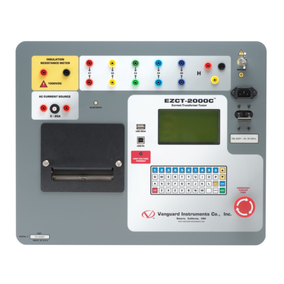
EZCT-2000C USER’S MANUAL EZCT-2000C Controls and Indicators The EZCT-2000C’s controls and indicators are shown in Figure 1 below. A leader line with an index number points to each control and indicator, which is cross-referenced to a functional description in Table 3. The table describes the function of each item on the control panel. The purpose of the controls and indicators may seem obvious, but users should become familiar with them before using the EZCT-2000C. -
Page 13: Table 3. Functional Descriptions Of Ezct-2000C Controls And Indicators
RESISTANCE METER Current transformer excitation voltage connectors. Each set of connectors contains a test voltage connector and sensing connector. The EZCT-2000C’s X X1, X2, X3, X4, X5 output terminals are rated to 2,200 Vac working voltage. Any voltage above 2,200 Vac will damage the input circuitry. -
Page 14: Pre-Test Setup
REV 1 EZCT-2000C USER’S MANUAL PRE-TEST SETUP Operating Voltages The EZCT-2000C’s operating voltage is preset at the factory for 100-120 Vac, 50/60 Hz or 200- 240 Vac, 50/60 Hz. LCD Screen Contrast Control [∧] To increase the LCD screen contrast, press and hold the key for two seconds. - Page 15 EZCT-2000C USER’S MANUAL REV 1 Replacing the Thermal Printer Paper The roll of thermal paper is housed inside a dispenser underneath the printer cover. To replace the paper, follow the steps below: • Unscrew the two large printer cover screws and remove the printer cover.
-
Page 16: Operating Procedures
Always connect the EZCT-2000C to the substation ground before connecting any test cables. The EZCT-2000C is supplied with five 20-foot X test cables and one 35-foot H cable. The X cable connections are required to run the current transformer excitation test. The H and X cable connections are required to run the transformer turns-ratio test. -
Page 17: Figure 3. Connections For A Typical High Resistance Measuring Application
EZCT-2000C USER’S MANUAL REV 1 Figure 3. Connections for a typical high resistance measuring application Figure 4. Connections for a typical insulation resistance measurement for a CT with 5 terminals... -
Page 18: Figure 5. Connections For Insulation Resistance Measurement For A Ct With 2 Terminals
REV 1 EZCT-2000C USER’S MANUAL Figure 5. Connections for a typical insulation resistance measurement for a CT with 2 terminals... -
Page 19: Figure 6. Ezct-2000C Ct Burden Test Cable Connection (Ezct-2000C Plus Only)
EZCT-2000C USER’S MANUAL REV 1 Figure 6. EZCT-2000C CT Burden Test Cable Connection (EZCT-2000C Plus Only) -
Page 20: Figure 7. Ezct-2000C Typical Current Source Connection (Ezct-2000C Plus Only)
REV 1 EZCT-2000C USER’S MANUAL Figure 7. EZCT-2000C Typical Current Source Connection (EZCT-2000C Plus Only) -
Page 21: Figure 8. Bushing Ct Connection On Delta Transformer
EZCT-2000C USER’S MANUAL REV 1 Figure 8. Bushing CT Connection on Delta Transformer Figure 9. Bushing CT Connection on Y Transformer... -
Page 22: Ezct-2000C X Input Voltage Warning
300 Vac is applied to the X1-X2 terminals, a voltage of 2,364 Vac (300 Vac x 7.88) will be induced at the X1-X4 terminals. If all the test leads are connected to the EZCT-2000C and the excitation test is performed on the X1-X2 terminals, the voltage induced at the X1-X4 terminals will exceed 2,000 Vac as the voltage across the X1-X2 terminals increases above 250 Vac. -
Page 23: Performing Tests
EZCT-2000C USER’S MANUAL REV 1 Performing Tests 3.3.1. Entering Test Record Header Information You can enter the test record header information before performing tests. The record header includes identifying information such as the company, station, circuit, model number, etc. Once the header information has been entered, it will apply to all subsequent test records. - Page 24 REV 1 EZCT-2000C USER’S MANUAL d. The following screen will be displayed: STATION: ↑↓ TO POSITION "enter" to accept [ENTER] Type the station name using the keypad and then press the key. e. The following screen will be displayed: CIRCUIT: CIRCUIT 1 ↑↓...
- Page 25 EZCT-2000C USER’S MANUAL REV 1 h. The following screen will be displayed: SERIAL NUMBER: 26002 ↑↓ TO POSITION "enter" to accept [ENTER] Type the serial number using the keypad and then press the key. i. The following screen will be displayed:...
-
Page 26: Performing Resistance, Excitation, And Ratio Tests
The following procedure describes the general steps for performing excitation, resistance, and ratio tests. a. When the EZCT-2000C is turned on, it will first go through a start-up cycle and load the firmware. Then the “START-UP” menu will be displayed as shown below: 1. - Page 27 EZCT-2000C USER’S MANUAL REV 1 Select a test voltage range by pressing the corresponding key ( e. If the selected test included an excitation test, the following screen will be displayed: SET TEST CURRENT: 1. 0.2A 2. 0.5A 3. 1A 4.
- Page 28 REV 1 EZCT-2000C USER’S MANUAL [ENTER] Press the key. The following screen will be displayed: ENTER PLATE RATIO: ENTER PLATE RATIO: 1000 : 0.0 1000 : 5.0 [ENTER] Type the second number using the keypad and then press the key.
- Page 29 EZCT-2000C USER’S MANUAL REV 1 i. The following screen will be displayed: ENTER BURDEN VA: (500.0 max) [ENTER] Type the burden value using the keypad and then press the key. j. The following screen will be displayed: ϕ ENTER cos (0.00 - 1.00)
- Page 30 REV 1 EZCT-2000C USER’S MANUAL m. If the selected test included a resistance test, the following screen will be displayed momentarily: CABLES ENERGIZED! 300V 1.0A x1-x2 DC RESISTANCE TEST The following screen will then be displayed: CABLES ENERGIZED! 300V 1.0A x1-x2 Ω...
- Page 31 (YES) if you would like to print the test results. The test results will be printed on the thermal printer. A typical EZCT-2000C tabulated test report printout is shown in Figure 11. A typical graphic report is shown in Figure 12.
- Page 32 REV 1 EZCT-2000C USER’S MANUAL r. The following screen will be displayed: RUN ANOTHER TEST? 1. YES 2. NO Press the key (NO). s. The following screen will be displayed: RUN INSUL RES TEST? 1. YES 2. NO Press the key (NO).
- Page 33 The following confirmation screen will then be displayed: RECORD NUMBER 1 has been saved! The test record number is automatically assigned to each test record stored in the EZCT-2000C’s Flash EEPROM. NOTE Press any key to return to the “START-UP” menu.
-
Page 34: Figure 11. Typical Ezct-2000C Tabulated Report Printout
REV 1 EZCT-2000C USER’S MANUAL Figure 11. Typical EZCT-2000C Tabulated Report Printout... -
Page 35: Table 4. Descriptions Of Tabulated Test Results Elements
Number Test record header information. The EZCT-2000C X terminals (taps) that were selected for this test. Test note for this particular test. The test note can be up to 20-characters long. Recorded excitation current readings on the CT secondary winding. -
Page 36: Figure 12. Typical Ezct-2000C Graphic Report With Multiple Plot Curves
REV 1 EZCT-2000C USER’S MANUAL Knee Point Marker Figure 12. Typical EZCT-2000C Graphic Report with Multiple Plot Curves... -
Page 37: Performing A Ct Burden Test (Ezct-2000C Plus Only)
EZCT-2000C USER’S MANUAL REV 1 3.3.3. Performing a CT Burden Test (EZCT-2000C Plus Only) The CT burden test verifies the actual CT burden before putting the CT in service. The CT’s secondary burden is measured by injecting a 1A or 5A test current into the load. To perform a CT burden test: a. - Page 38 REV 1 EZCT-2000C USER’S MANUAL b. Start from the “START-UP” menu: 1. RUN TEST 04/16/13 2. SETUP 07:47:57 3. TEST PLANS 4. DIAGNOSTICS 5. CURRENT SOURCE Press the key (RUN TEST). c. The following screen will be displayed: 1. Res, excit & ratio 2.
- Page 39 EZCT-2000C USER’S MANUAL REV 1 f. The following screen will be displayed: test 1 parameters: 1 amp burden test connect x1-x2 cables to burden now. "Start" to begin [START] Press the key to begin the test. g. The following screen will be displayed: CABLES ENERGIZED! I=0.0016 AMPS...
- Page 40 REV 1 EZCT-2000C USER’S MANUAL CABLES ENERGIZED! BURDEN TEST RESULTS 2.983 VA ϕ = 0.92 Then, the following screen will be displayed: print test results? 1. YES 2. NO Print the key (YES) if you would like to print the test results. The test results will be printed on the thermal printer.
-
Page 41: Figure 13. Ezct-2000C Typical Burden Test Results Report Printout
EZCT-2000C USER’S MANUAL REV 1 SAVING RECORD... PLEASE WAIT... j. The following confirmation screen will be displayed: RECORD NUMBER 1 has been saved! Press any key to return to the “START-UP” menu. Figure 13. EZCT-2000C Typical Burden Test Results Report Printout... -
Page 42: Performing An Insulation Resistance Test
REV 1 EZCT-2000C USER’S MANUAL 3.3.4. Performing an Insulation Resistance Test To perform an insulation resistance test: a. Make connections per Figure 12, 13, or 14 below: Figure 14. Connections for a typical high resistance measuring application Figure 15. Connections for a typical insulation resistance measurement for a CT with 5 terminals... - Page 43 EZCT-2000C USER’S MANUAL REV 1 b. Start from the “START-UP” menu: 1. RUN TEST 04/17/13 2. SETUP 07:11:13 3. TEST PLANS 4. DIAGNOSTICS 5. CURRENT SOURCE Press the key (RUN TEST). c. The following screen will be displayed: 1. Res, excit & ratio 2.
- Page 44 REV 1 EZCT-2000C USER’S MANUAL f. The following screen will be displayed: TEST 1 PARAMETERS 500V INS RES TEST CONNECT INS REST TEST CABLES NOW. "START" TO BEGIN [START] Connect the insulation resistance cables and then press the key. g. The following screen will be displayed:...
- Page 45 EZCT-2000C USER’S MANUAL REV 1 The following screen will then be displayed: print test results? 1. YES 2. NO Press the key (YES) if you would like to print the test results. The test results will be printed on the thermal printer. A typical insulation resistance test results report is shown in Figure 17.
-
Page 46: Figure 17. Ezct-2000C Typical Insulation Resistance Test Results Report Printout
REV 1 EZCT-2000C USER’S MANUAL RECORD NUMBER 1 has been saved! Press any key to return to the “START-UP” menu. Figure 17. EZCT-2000C Typical Insulation Resistance Test Results Report Printout... -
Page 47: Performing A Current Source Test (Ezct-2000C Plus Only)
3.3.5. Performing a Current Source Test (EZCT-2000C Plus Only) The EZCT-2000C Plus’s programmable current source can be used to verify CT loads. The EZCT- 2000C Plus can output up to a 20A current (0-15Vac). To perform a current source test: a. - Page 48 A timer will display the elapsed time that the current has been on. The EZCT-2000C is thermally protected and will automatically shut off if the transformer reaches an over-temperature condition. Since the EZCT-2000C can provide up to a 20A current, the transformer can get to thermal NOTE protection mode if operated for a long time at a high current.
-
Page 49: Working With Test Records
3.4.1. Restoring and Printing a Test Record From Flash EEPROM You can restore a test record from the EZCT-2000C’s Flash EEPROM to the working memory. You can then print the restored test record on the unit’s built-in thermal printer. To restore a test record: a. - Page 50 REV 1 EZCT-2000C USER’S MANUAL 1. INTERNAL STORAGE 2. THUMB DRIVE Press the key (INTERNAL STORAGE). The following screen will then be displayed: RESTORE RECORD 1. enter record number 2. scroll to select Continue with the steps below. 1. ENTER RECORD NUMBER If you know the record number that you would like to restore, press the key.
- Page 51 EZCT-2000C USER’S MANUAL REV 1 2. SCROLL TO SELECT Press the key if you would like to scroll through a directory of the stored test records. The following screen will be displayed: RECORD DIRECTORY "UP" TO SCROLL FWD "DWN" TO SCROLL RVS [∧]...
- Page 52 REV 1 EZCT-2000C USER’S MANUAL Press the key to print the tabulated data and graphics results on the thermal printer. The test record will be restored to the working memory and will be printed on the thermal printer, and then you will be returned to the “START-UP” menu.
-
Page 53: Restoring And Printing A Test Record From A Usb Flash Drive
REV 1 3.4.2. Restoring and Printing a Test Record From a USB Flash Drive You can restore a test record from a USB Flash drive to the EZCT-2000C’s working memory using the steps below: a. Make sure the USB Flash drive containing the test record(s) is inserted in the EZCT- 2000C’s USB Flash drive port (“USB MEM”... - Page 54 REV 1 EZCT-2000C USER’S MANUAL e. The following screen will be displayed: RESTORE THUMB DRIVE REC_ [ENTER] Type the record number that you would like to restore and press the key. If you do not know the record number, you can print a test record directory. Please see section 3.4.5 for details.
- Page 55 EZCT-2000C USER’S MANUAL REV 1 Press the key to print the test report and graphic results on the thermal printer, without the excitation voltage and current data points. After printing has finished, you will be returned to the “START-UP” menu.
-
Page 56: Printing A Restored Test Record
REV 1 EZCT-2000C USER’S MANUAL 3.4.3. Printing a Restored Test Record You can print a test record at the time that it is restored from the Flash EEPROM or a USB Flash drive (see section 3.4.1), or you can restore it to the working memory and print it later. To print the current test record in the working memory: a. - Page 57 EZCT-2000C USER’S MANUAL REV 1 Press the key to print the tabulated data and graphics results on the thermal printer. The test record will be printed on the thermal printer and you will be returned to the “START-UP” menu. Press the key to print the test report and graphic results on the thermal printer, without the excitation voltage and current data points.
-
Page 58: Printing A Directory Of Test Records Stored In The Ezct-2000C's Memory
EZCT-2000C USER’S MANUAL 3.4.4. Printing a Directory of Test Records Stored in the EZCT-2000C’s Memory You can print a directory of all the test records stored in the EZCT-2000C’s Flash EEPROM using the steps below: a. Start from the “START-UP” menu: 1. - Page 59 The short directory option prints the last 10 records stored in the EZCT-2000C’s Flash EEPROM. The short directory listing will be printed on the thermal printer and you will be...
-
Page 60: Figure 18. Typical Internal Test Record Directory Printout
REV 1 EZCT-2000C USER’S MANUAL Figure 18. Typical Internal Test Record Directory Printout... -
Page 61: Printing A Directory Of Test Records Stored In A Usb Flash Drive
You can print a directory of all the test records stored in a USB Flash drive using the steps below: a. Make sure the USB Flash drive is inserted in the EZCT-2000C’s USB Flash drive port (“USB MEM” port). Then start from the “START-UP” menu: 1. -
Page 62: Figure 19. Typical Usb Flash Drive Record Directory Printout
REV 1 EZCT-2000C USER’S MANUAL Figure 19. Typical USB Flash Drive Record Directory Printout... -
Page 63: Copying Test Records To A Usb Flash Drive
REV 1 3.4.6. Copying Test Records to a USB Flash Drive You can easily copy test records stored in the EZCT-2000C’s Flash EEPROM to a connected USB Flash drive using the steps below: a. Make sure a USB Flash drive is inserted in the EZCT-2000C’s Flash drive port (“USB MEM”... - Page 64 1. COPY SINGLE RECORD Press the key (COPY SINGLE RECORD) if you would like to copy a single record from the EZCT-2000C to the USB Flash drive. The following screen will be displayed: ENTER RECORD NUMBER to copy to flash drv...
- Page 65 2. COPY ALL RECORDS Press the key (COPY ALL RECORDS) if you would like to copy all the test records from the EZCT-2000C to the USB Flash drive. The following screen will be displayed: SAving record 1 to thumb drive Please wait...
-
Page 66: Erasing Test Records From The Flash Eeprom
REV 1 EZCT-2000C USER’S MANUAL 3.4.7. Erasing Test Records From the Flash EEPROM You can erase individual or all test records stored in the EZCT-2000C’s Flash EEPROM. To erase a test record: a. Start from the “START-UP” menu: 1. RUN TEST 04/18/13 2. - Page 67 EZCT-2000C USER’S MANUAL REV 1 ERASE RECORD 1. ERASE SINGLE REC. 2. ERASE ALL RECORDS "STOP" TO EXIT Continue with the steps below: 1. ERASE SINGLE REC. Press the key if you would like to erase a single record. The following screen...
- Page 68 EZCT-2000C USER’S MANUAL 2. ERASE ALL RECORDS Press the key if you would like to erase all of the test records stored in the EZCT-2000C’s flash EEPROM. The following confirmation screen will be displayed: ERASE ALL RECORDS! Are you sure? "ENTER"...
-
Page 69: Erasing Test Records From A Usb Flash Drive
You can erase individual or all test records stored in a USB Flash drive. To erase a test record: a. Make sure the USB Flash drive is inserted in the EZCT-2000C’s USB Flash drive port (“USB MEM” port). Then start from the “START-UP” menu: 1. - Page 70 REV 1 EZCT-2000C USER’S MANUAL d. The following screen will be displayed: ERASE RECORD 1. ERASE SINGLE REC. 2. ERASE ALL RECORDS "STOP" TO EXIT 1. ERASE SINGLE REC. Press the key (ERASE SINGLE REC.) if you would like to erase a single record.
- Page 71 EZCT-2000C USER’S MANUAL REV 1 2. ERASE ALL RECORDS Press the key (ERASE ALL RECORDS) if you would like to erase all of the test records stored in the USB Flash drive. The following confirmation screen will be displayed: ERASE ALL THUMB DRIVE...
-
Page 72: Working With Test Plans
CT load burden test definitions. Up to 10 test definitions can be stored per test plan, and up to 128 CT test plans can be stored in the EZCT-2000C’s Flash EEPROM. The ability to use test plans makes CT testing an extremely simple process. To perform a test, the EZCT-2000C is connected to the CT terminals and a test plan is selected to run. - Page 73 TEST PLAN #001 SAVED! The test plan will be extracted from the test record in the working memory and will be saved to the EZCT-2000C’s Flash EEPROM as a new test plan. The test plan number will be automatically incremented by the EZCT-2000C.
-
Page 74: Printing A Directory Of Test Plans Stored In The Ezct-2000C's Memory
EZCT-2000C USER’S MANUAL 3.5.2. Printing a Directory of Test Plans Stored in the EZCT-2000C’s Memory You can print a directory of all the test plans stored in the EZCT-2000C’s Flash EEPROM using the steps below: a. Start from the “START-UP” menu: 1. -
Page 75: Figure 20. Typical Ezct-2000C Flash Eeprom Test Plan Directory Printout
REV 1 You will be automatically returned to the “START-UP” menu after the directory printing is finished. A typical Flash EEPROM test plan directory printout is shown in Figure 20. Figure 20. Typical EZCT-2000C Flash EEPROM Test Plan Directory Printout... -
Page 76: Printing A Directory Of Test Plans Stored In A Usb Flash Drive
To print a directory of all the test plans stored in a USB Flash drive: a. Make sure the USB Flash drive is inserted in the EZCT-2000C’s USB Flash drive port (“USB MEM” port). Then start from the “START-UP” menu: 1. -
Page 77: Figure 21. Typical Usb Flash Drive Test Plan Directory Printout
EZCT-2000C USER’S MANUAL REV 1 Figure 21. Typical USB Flash Drive Test Plan Directory Printout... -
Page 78: Printing A Test Plan
REV 1 EZCT-2000C USER’S MANUAL 3.5.4. Printing a Test Plan To print a test plan: a. Start from the “START-UP” menu: 1. RUN TEST 04/19/13 2. SETUP 10:14:25 3. TEST PLANS 4. DIAGNOSTICS 5. CURRENT SOURCE Press the key (TEST PLANS). -
Page 79: Table 5. Description Of Test Plan Elements
EZCT-2000C USER’S MANUAL REV 1 Figure 22. Typical Test Plan Printout Table 5. Description of Test Plan Elements Item Description Number Number of tests in test plan (1) Tests to be performed (Resistance, excitation, turns ratio, insulation, and CT load burden) -
Page 80: Erasing Test Plans From The Flash Eeprom
2. ERASE ALL PLANS The above screen will be displayed only if a USB Flash drive is NOT connected to the EZCT-2000C’s USB Flash drive port. If a USB Flash drive is connected, the following screen will be displayed: NOTE 1. - Page 81 EZCT-2000C USER’S MANUAL REV 1 ERASE TEST PLAN 1. ERASE SINGLE PLAN 2. ERASE ALL PLANS Continue with the steps below: 1. ERASE SINGLE PLAN Press the key if you would like to erase a single test plan. The following...
- Page 82 REV 1 EZCT-2000C USER’S MANUAL ERASE ALL PLANS! Are you sure? "ENTER" TO CONTINUE. [STOP] If you would like to cancel the erasure process, press the key. No test plans will be erased and you will be returned to the “START-UP” menu.
-
Page 83: Erasing Test Plans From A Usb Flash Drive
3.5.6. Erasing Test Plans From a USB Flash Drive To erase one or all test plans stored on a USB Flash drive: a. Make sure the USB Flash drive is inserted in the EZCT-2000C’s USB Flash drive port (“USB MEM” port). Then start from the “START-UP” menu: 1. - Page 84 REV 1 EZCT-2000C USER’S MANUAL Press the key (ERASE SINGLE PLAN) if you would like to erase a single plan from the USB Flash drive. The following screen will be displayed: ERASE THUMB DRIVE PLAN_ [ENTER] Type the test plan number that you would like to erase and press the key.
- Page 85 EZCT-2000C USER’S MANUAL REV 1 ERASING all thumb drive test plans PLEASE WAIT... The following screen will be displayed after all of the test plans have been erased from the USB Flash drive: all thumb drive test plans erased! Press any key to return to the “START-UP” menu.
-
Page 86: Loading A Test Plan From The Ezct-2000C's Flash Eeprom
LOAD TEST PLAN NUMBER: The above screen will be displayed only if a USB Flash drive is NOT connected to the EZCT-2000C’s USB Flash drive port. If a USB Flash drive is connected, the following screen will be displayed: NOTE 1. - Page 87 EZCT-2000C USER’S MANUAL REV 1 LOAD TEST PLAN NUMBER: Continue with the steps below: [ENTER] Type the test plan number that you would like to load and press the key. If you do not know the test plan number, you can print a test plan directory using the instructions in section 3.5.2.
-
Page 88: Loading A Test Plan From A Usb Flash Drive
3.5.8. Loading a Test Plan from a USB Flash Drive To load a test plan from a USB Flash drive: a. Make sure the USB Flash drive is inserted in the EZCT-2000C’s USB Flash drive port (“USB MEM” port). Then start from the “START-UP” menu: 1. - Page 89 Press the key if you would like the loaded test plan to be also saved in the EZCT-2000C’s Flash EEPROM. Any existing test plans in the EZCT-2000C’s Flash EEPROM will not be over-written. The EZCT-2000C will automatically assign a new test plan number and store the test plan in the next available memory location.
-
Page 90: Running A Test Using A Loaded Test Plan
The following screen will be displayed: CABLES WILL BE ENERGIZED! "START" TO BEGIN [START] Press the key and the EZCT-2000C will start running the test per the test plan settings. The screen will be updated with the test status. - Page 91 EZCT-2000C USER’S MANUAL REV 1 When the test has finished, the following screen will be displayed: SAVE THIS RECORD? 1. YES 2. NO Press the key (YES) to save the record. The following screen will be displayed momentarily: SAVING RECORD...
- Page 92 "START" to begin [START] Press the key to begin the test. e. The EZCT-2000C will start performing the test per the test plan parameters. When the test has finished, the following screen will be displayed: ANY KEY TO CONTINUE =63.4 =0.3174...
- Page 93 EZCT-2000C USER’S MANUAL REV 1 g. The following screen will be displayed: KEEP THIS TEST? 1. YES 2. NO Press the key (YES) to keep the test results. h. The following screen will be displayed: SAVE THIS RECORD? 1. YES 2.
-
Page 94: Unloading A Test Plan From The Working Memory
REV 1 EZCT-2000C USER’S MANUAL 3.5.10. Unloading a Test Plan from the Working Memory To unload the test plan from the working memory and clear all the test plan parameters: a. Start from the “START-UP” menu: 1. RUN TEST 04/19/13 2. -
Page 95: Changing Setup Parameters
EZCT-2000C USER’S MANUAL REV 1 CHANGING SETUP PARAMETERS Setting the Knee Point Marker Use the steps below to change the knee point marker for the excitation graph: a. Start from the “START-UP” menu: 1. RUN TEST 05/02/13 2. SETUP 02:115:20 3. -
Page 96: Figure 23. Graphic Report Showing Knee Point Marker
REV 1 EZCT-2000C USER’S MANUAL d. The following screen will be displayed: 1. IEEE 30 DEGREE 2. IEEE 45 DEGREE 3. IEC 10%V --> 50%I Press either the key (IEEE 30 DEGREE), the key (IEEE 45 DEGREE), or the (IEC 10%V --> 50%I) to select the desired knee point marker. The knee point marker will be set and you will be returned to the “START-UP”... -
Page 97: Enabling And Disabling The Buried Ct In Transformer Delta Option
EZCT-2000C USER’S MANUAL REV 1 Enabling and Disabling the Buried CT in Transformer Delta Option 4.2.1. Enabling the Buried CT in Transformer Delta Option If you are measuring the turns ratio of a CT buried in the transformer Delta windings (see Figure 24 and Figure 25 and also page 94 for further information), you must first select the “Buried CT... -
Page 98: Disabling The Buried Ct In Transformer Delta Option
REV 1 EZCT-2000C USER’S MANUAL Press the key (BURIED CT DELTA ON). e. The following screen will be displayed: RATIOS WILL BE ADJUSTED by 2/3. ARE YOU SURE? 1. YES 2. NO Press the key (YES). f. The following screen will be displayed:... - Page 99 EZCT-2000C USER’S MANUAL REV 1 b. The following screen will be displayed: 1. RECORD ID 2. PRINT RECORD 3. RECORD DIRECTORY 4. SAVE/RES RECORD 5. ERASE RECORD 6. NEXT PAGE Press the key (NEXT PAGE). c. The following screen will be displayed: 1.
-
Page 100: Figure 24. Buried Ct In A Delta Transformer Illustration 1
REV 1 EZCT-2000C USER’S MANUAL Figure 24. Buried CT in a Delta Transformer Illustration 1 Figure 25. Buried CT in a Delta Transformer Illustration 2... - Page 101 • The CT turns ratio is now measured as Ratio = or Ratio = ( ). This measured turns ratio is higher than the actual turns ratio. • The EZCT-2000C will display the correct CT turns ratio by adjusting the measured turns ratio by...
-
Page 102: Setting The Clock
REV 1 EZCT-2000C USER’S MANUAL Setting the Clock To set the EZCT-2000C’s internal clock: a. Start from the “START-UP” menu: 1. RUN TEST 05/02/13 2. SETUP 14:14:25 3. TEST PLANS 4. DIAGNOSTICS 5. CURRENT SOURCE Press the key (SETUP). b. The following screen will be displayed: 1. -
Page 103: Setting The Preferred Interface Language
EZCT-2000C USER’S MANUAL REV 1 Setting the Preferred Interface Language Follow the steps below to set the preferred language for the EZCT-2000C's interface (English, Spanish, and Turkish are supported): a. Start from the "START-UP" menu: 1. RUN TEST 05/02/13 2. SETUP 14:14:25 3. - Page 104 REV 1 EZCT-2000C USER’S MANUAL e. A confirmation message will be displayed as shown below: ENGLISH SET Press any key to return to the "START-UP" menu. Menu items and messages will now be displayed in the selected language.
-
Page 105: Printing Raw Memory Buffer Data
REV 1 Printing Raw Memory Buffer Data You can print the raw data from the EZCT-2000C’s memory buffer for diagnostic purposes. This will print a table of current and voltage values stored in the unit’s working memory. To print the raw buffer data: a. -
Page 106: Disabling The H Voltage Checking Feature
EZCT-2000C USER’S MANUAL Disabling the H Voltage Checking Feature The EZCT-2000C's H Voltage input can only handle voltage up to 100 Vac. When a saturation test is being performed, the unit monitors the H voltage and stops the saturation test if a voltage above 100 Vac is detected. - Page 107 EZCT-2000C USER’S MANUAL REV 1 d. The following screen will be displayed: DISABLE H OVER-VTG CHECK. ARE YOU SURE? 1. YES 2. NO Press the key (YES). e. The following confirmation screen will be displayed: H CABLE OVER VOLTAGE CHECK DISABLED! Press any key to return to the "START-UP"...
-
Page 108: Diagnostics, Verification, And Troubleshooting
REV 1 EZCT-2000C USER’S MANUAL DIAGNOSTICS, VERIFICATION, AND TROUBLESHOOTING Performing a Diagnostics Test The Diagnostics test mode displays the output voltage at the selected X leads (V ), the voltage sensed by the H leads (V ), and the X voltage excitation current (I ). - Page 109 EZCT-2000C USER’S MANUAL REV 1 d. The following screen will be displayed: caution! cables will be energized! "ENTER" to continue [ENTER] Press the key to continue. e. The following screen will be displayed and the V , and I values will be continuously...
-
Page 110: Verifying The Ezct-2000C's
Verifying the EZCT-2000C’s V Sense Circuit Using an External Meter The excitation voltage (V ) sensed by the EZCT-2000C can be verified using an external RMS volt meter. Follow the steps below to verify the EZCT-2000C’s V sense circuit: a. Connect the X cables to an RMS volt meter as shown in Figure 26. -
Page 111: Verifying The Ezct-2000C's I X Sense Circuit Using An External Meter
You can verify the excitation current (I ) sensed by the EZCT-2000C by using an external RMS ampere meter. Follow the steps below to verify the EZCT-2000C’s I sense circuit: a. Connect the X cables to a power resistor and an RMS ampere meter as shown in Figure b. -
Page 112: Quickly Verifying The Ezct-2000C's Turns Ratio Circuit
EZCT-2000C USER’S MANUAL Quickly Verifying the EZCT-2000C’s Turns Ratio Circuit You can quickly verify the EZCT-2000C’s turns ratio circuit by performing the following ratio test: a. Connect the X1 test lead to the H1 test lead as shown in Figure 28. -
Page 113: Troubleshooting Guide
The excitation current can be raised during a test. When running the • The EZCT-2000C X cable is driving an • Check the CT terminal connection. excitation test, the V opened circuit. voltage can be raised but the excitation current is always zero during a test. -
Page 114: Appendix A - Calculating Turns Ratio On A Shunt Reactor
REV 1 EZCT-2000C USER’S MANUAL Appendix A - Calculating Turns Ratio on a Shunt Reactor The Vanguard EZCT line of products use the voltage method to measure the turns-ratio on current transformers. A typical connection for a stand-alone CT is shown in Figure 29. -
Page 115: Figure 30
EZCT-2000C USER’S MANUAL REV 1 Figure 30 shows a typical connection of a CT mounted on the primary bushing of a single phase transformer. When the voltage V1 is introduced to the CT's secondary winding, there is an induced voltage (V3) on the primary winding of this single phase transformer. Since the only... -
Page 116: Figure 31
REV 1 EZCT-2000C USER’S MANUAL Since this is a single phase transformer, and the transformer secondary winding is accessible, the user can apply a jumper to short out the transformer secondary winding as shown in Figure 31. By shorting out the transformer secondary winding, the user can eliminate most of the V3 voltage (V3=0V). -
Page 117: Figure 32
EZCT-2000C USER’S MANUAL REV 1 Figure 32 shows a CT mounted on an auto-transformer. This configuration is very similar to the CT mounted on a single phase transformer, the main difference being that the secondary winding is part of the primary winding. -
Page 118: Figure 33
REV 1 EZCT-2000C USER’S MANUAL Figure 33 show a CT mounted on a typical shunt reactor. This configuration is very similar to the CT mounted on a single phase transformer, the main difference being the lack of the secondary winding! The turns-ratio in this case will be:... -
Page 119: Figure 34
EZCT-2000C USER’S MANUAL REV 1 Figure 34 show a CT with 5 taps. The turns-ratio of the CT can be measured by treating the CT secondary winding as an auto-transformer. When using this method, the effect of the shunt reactor winding is totally eliminated. -
Page 120: Figure 35
REV 1 EZCT-2000C USER’S MANUAL A common practice for verifying the CT turns-ratio in the field is to apply an AC voltage to the CT secondary full winding (X1-X5). A volt meter can be used to verify the voltage drop across the CT terminals. -
Page 121: Figure 36
EZCT-2000C USER’S MANUAL REV 1 Figure 36 Figure 37... - Page 122 1520 S. Hellman Ave • Ontario, CA 91761 • USA Phone: 909-923-9390 • Fax: 909-923-9391 www.vanguard-instruments.com Copyright © 2014 by Vanguard Instruments Company, Inc. EZCT-2000C User’s Manual • Revision 1.4 • June 6, 2014 • TA...
Need help?
Do you have a question about the EZCT-2000C and is the answer not in the manual?
Questions and answers