
Related Manuals for Vanguard Instruments Company CBCT


Summary of Contents for Vanguard Instruments Company CBCT
- Page 1 CBCT CIRCUIT BREAKER COIL TESTER USER’S MANUAL Vanguard Instruments Company, Inc. 1520 S. Hellman Ave. Ontario, California 91761, USA TEL: (909) 923-9390 August 2010 FAX: (909) 923-9391 Revision 1...
- Page 2 SAFETY WARNING AND CAUTIONS The CBCT shall be used only by trained operators. All devices under test shall be off-line and fully isolated. DO NOT MODIFY TEST EQUIPMENT To avoid the risk of introducing additional or unknown hazards, do not install substitute parts or perform any unauthorized modification to any CBCT test unit.
-
Page 3: Table Of Contents
Figure 1. CBCT Controls and Indicators................... 4 Figure 2. CBCT Constant Output to CB Control Circuits ..............6 Figure 3. Direct Connection from CBCT Pulse Output to CB Trip Coil ..........7 Figure 4. Direct Connection from CBCT Pulse Output to CB Close Coil .......... 7 Figure 5. -
Page 4: Conventions Used In This Document
CBCT USER’S MANUAL REV 1 CONVENTIONS USED IN THIS DOCUMENT This document uses the following conventions: A key, switch, or knob on the CBCT is indicated as , and [KEY] [SWITCH] [KNOB] • Menu names are referenced as “MENU NAME”... -
Page 5: Introduction
Input Voltage The CBCT’s input voltage range is from 20 to 300 Vdc. The input circuit is also protected from a reversed polarity connection. Output Voltage The output voltage is programmable from 5% to 95% of the input voltage and is set using the dial on the front panel. -
Page 6: Technical Specifications
CBCT USER’S MANUAL REV 1 Technical Specifications Table 1. CBCT Technical Specifications TYPE Programmable DC Power Supply PHYSICAL SPECIFICATIONS 19”W x 7”H x 15”D, (48 cm x 17 cm x 38 cm); Weight: 25 lbs (11.3 kg) INPUT VOLTAGE 20 – 300 Vdc, 20A fuse OUTPUT VOLTAGE 5% –... -
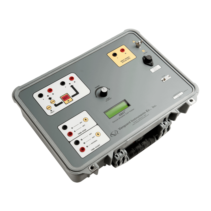
Page 7: Cbct Controls And Indicators
CBCT USER’S MANUAL CBCT Controls and Indicators The CBCT’s controls and indicators are shown in Figure 1 below. A leader line with an index number points to each control and indicator, which is cross-referenced to a functional description in Table 2. The table describes the function of each item on the control panel. The purpose of the controls and indicators may seem obvious, but users should become familiar with them before using the CBCT. -
Page 8: Table 2. Functional Descriptions Of Cbct Controls And Indicators
CBCT USER’S MANUAL REV 1 Table 2. Functional Descriptions of CBCT Controls and Indicators Item Panel Markings Functional Description Number Pulse output voltage. Constant output has to be on first. Press PULSE switch to output voltage. Output voltage is turned on for 1 second. LED indicator is lit when output is on. -
Page 9: Operating Procedures
OPERATING PROCEDURES CBCT Cable Connections Typical CBCT DC control connection diagrams are shown below. Figure 2 illustrates the CBCT “Constant Output” connection to the circuit breaker control circuit. Figure 3 and Figure 4 illustrate the CBCT “Pulse Output” connection to the circuit breaker Trip and Close coil. -
Page 10: Figure 3. Direct Connection From Cbct Pulse Output To Cb Trip Coil
CBCT USER’S MANUAL REV 1 Figure 3. Direct Connection from CBCT Pulse Output to CB Trip Coil Figure 4. Direct Connection from CBCT Pulse Output to CB Close Coil... -
Page 11: Setting The Output Voltage
[CONTROL KNOB] If the ‘Constant’ output connection is being used, the circuit breaker control circuit voltage is powered with the voltage displayed on the CBCT screen. The circuit breaker is now ready to be operated by the control switches. If the ‘Pulse’ output connection is being used, press the... -
Page 12: Cbct Timer Start Input
[Arrow] key. The LED will be lit next to the label for the currently selected mode. The CBCT timer can be started in three selectable modes: internal, wet input, and dry input. Each mode is described below: • Internal Mode... -
Page 13: Cbct Timer Stop Input
• Dry Contact Mode In this mode, the timer will look for a change in the Stop Input terminals to stop the timer. The CBCT will output a DC voltage to the Stop Input terminals to detect the dry contact status. - Page 14 1520 S. Hellman Ave • Ontario, CA 91761 • USA Phone: 909-923-9390 • Fax: 909-923-9391 www.vanguard-instruments.com Copyright © 2009 by Vanguard Instruments Company, Inc. CBCT User’s Manual • Revision 1.0 • August 18, 2010 • TA...
Need help?
Do you have a question about the CBCT and is the answer not in the manual?
Questions and answers