
Related Manuals for Planer BT37 MarkII


Summary of Contents for Planer BT37 MarkII
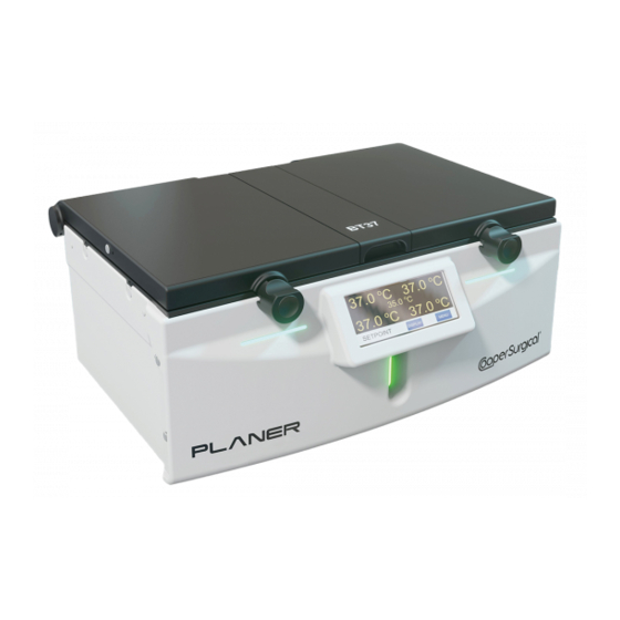
- Page 1 ® BT37 MarkII Model No: BT37-02 Service Manual © 2021 Planer Limited Original Instructions MA200606 1.0.0...
-
Page 3: Table Of Contents
Switching off ........................ 34 Component replacement Opening the BT37 ......................36 Lid seal .......................... 39 Upper heater ribbon cable ..................40 External air filter ......................46 Internal air filter ......................47 Fan ..........................48 BT37 MarkII: Service Manual MA200606 1.0.0... - Page 4 Regular checks General cleaning Resetting the access code 10. Cleaning and disinfecting the chamber 11. Checking the liquid level indicator 12. Checking the battery 13. Calibration and servicing 14. Safety testing 15. Testing the alarms BT37 MarkII: Service Manual MA200606 1.0.0...
- Page 5 20. Configuring BT37 toolbox for manual calibration 21. Manual calibration 22. Diagrams and schematics 22.1 Pneumatic block diagram ..................165 22.2 BT37 MarkII exploded diagram ................. 166 23. Additional information 23.1 External alarm connection ..................168 23.2 Network security ....................... 168 23.3...
-
Page 7: Introduction
Introduction... -
Page 8: About The Equipment
Mode Heaters Note Standby The system is inactive and ready to be switched off. Bottle change The system is waiting for the humidifier to be changed. Controlled Controlled This is the normal operating state. BT37 MarkII: Service Manual MA200606 1.0.0... -
Page 9: Front View
1.1.3 Side view 1. Rear of base monitoring port for independent temperature probes. 2. Lid monitoring port for independent temperature probes. 3. Front of base monitoring port for independent temperature probes. BT37 MarkII: Service Manual MA200606 1.0.0... -
Page 10: Rear View
In normal operation, the display shows the current status of the incubator. Pressing the Display button cycles through different screens, each of which shows different information about the state of incubator. An example is shown below. BT37 MarkII: Service Manual MA200606 1.0.0... -
Page 11: Numeric Entry
Numeric entry Some screens require a numeric entry to be entered. At these screens a keypad appropriate to the required entry will be displayed. The screen for an access code entry is shown below. BT37 MarkII: Service Manual MA200606 1.0.0... -
Page 12: Menus
The status indicators on the front of the BT37 show the current state of the system. These are used along with an internal buzzer and the external alarm. The state of the indicators, buzzer and external alarm in various states are shown below. BT37 MarkII: Service Manual MA200606 1.0.0... -
Page 13: Acknowledging An Alarm
Use in well ventilated areas. Risk of asphyxiation from carbon dioxide released from the equipment. Additional ventilation may be required. Consider carbon dioxide alarms in confined spaces. Refer to the Gas supply topic for gas release rates. BT37 MarkII: Service Manual MA200606 1.0.0... -
Page 14: Precautions
External alarm connection must use fully screened cable no longer than 2 m. Take care to avoid placing the BT37 in environments influenced by sources of electromagnetic interference, such as large transformers for example. BT37 MarkII: Service Manual MA200606 1.0.0... -
Page 15: Symbols
USA: Caution: Federal law restricts this device to sale by Rx only or on the order of a physician or a practitioner trained in its use. Sterilized using irradiation Do not reuse. Do not use if packaging is broken. BT37 MarkII: Service Manual MA200606 1.0.0... -
Page 16: Equipment List
SWAGELOK 1/4x1/4x42in. lg PTFE HOSE AM101450 SOLENOID VALVE ASSEMBLY (H.F) AM101447 SOLENOID VALVE ASSEMBLY (L.F) AM101451 FAN ASSEMBLY AM101659 TRANSLUCENT HUMIDIFIER LID ASSEMBLY AP101204 INCUBATOR HUMIDIFIER RIGHT PCB ASSEMBLY AP101206 INCUBATOR TOP HEATER PCB ASSEMBLY BT37 MarkII: Service Manual MA200606 1.0.0... -
Page 17: Changing The Ip Address
TOUCH SCREEN DISPLAY AP101425 INCUBATOR LEFT HUMIDIFIER ASSEMBLY AY102187 UPPER CABLE REPLACEMENT KIT AY200288 BT37 MARKII THREE TUBE BOTTLE HUMIDIFIER KIT BT101376 GELLED BATTERY 12V CO101378 IEC INLET 2 FUSED FILTER 4A FA101707 FAN FILTER MEDIA 60 x 60 x 2.8 45PPI... - Page 18 The IP address of your BT37 will be displayed in the position below. Ensure that this is the correct IP address if you have more than one device connected to your laptop/PC. Select Assign IP and click Next. BT37 MarkII: Service Manual MA200606 1.0.0...
- Page 19 Change the IP address displayed to that of the laptop/PC and increment it by 1. So If the laptop/PC is 169.254.84.201, then change the BT37 to 169.254.84.202. Ensure that this IP address is not being used by another device. Click Next. Click the assign button BT37 MarkII: Service Manual MA200606 1.0.0...
- Page 20 Introduction The window below confirms the change of IP address. BT37 MarkII: Service Manual MA200606 1.0.0...
-
Page 21: Operation
Operation... -
Page 22: Setting The Access Code
Setting the access code Access to the BT37 settings requires an access code to be entered. This is a 5 digit number used to control access to the menus. This can be changed as follows: BT37 MarkII: Service Manual MA200606 1.0.0... -
Page 23: Changing The Control Settings
Extended purge flow provides gas at the same flow as the normal purge flow but for an extended duration defined by the Extended purge duration s setting. The default BT37 MarkII: Service Manual MA200606 1.0.0... -
Page 24: Non-Pulsed Bleed Flow
5. Remove the existing bottle if fitted. 6. Install a new bottle. There are two bottle systems available for the BT37. Which one is used can be determined from the seal fitted to the chamber lids. BT37 MarkII: Service Manual MA200606 1.0.0... - Page 25 2. The single tube system also includes a small cylindrical seal that seals the tube entry towards the centre of the chamber base. Refer to the Single tube bottle humidifier section for details on how to change the bottle. BT37 MarkII: Service Manual MA200606 1.0.0...
-
Page 26: Single Tube Bottle Humidifier
1. Inspect the bottle and tubing. Do not use if the tubing is kinked or damaged. 2. Fill the bottle with 125 mL of sterile, distilled water. 3. Remove the cap from the luer fitting on the inlet tube and replace with the filter. BT37 MarkII: Service Manual MA200606 1.0.0... - Page 27 Operation 4. Press the bottle cap onto the bottle. Ensure the tubes are aligned with the bottle. BT37 MarkII: Service Manual MA200606 1.0.0...
- Page 28 5. Open the humidifier and the left and right-hand chamber lids. 6. Fit the bottle. Press in firmly and ensure the orientation is correct. 7. Ensure the bottle arms are seated correctly in the base of the left and right-hand chambers. BT37 MarkII: Service Manual MA200606 1.0.0...
- Page 29 9. Fit the filter to the gas inlet. 10. Check the tube. Ensure there are no kinks. 11. Ensure the centre groove seals are in place. These are not normally removed or replaced and should already be in position. BT37 MarkII: Service Manual MA200606 1.0.0...
-
Page 30: Three Tube Bottle Humidifier
2. Fill the bottle with 125 mL of sterile, distilled water. 3. Remove the cap from the luer fitting on the inlet tube and replace with the filter. 4. Press the bottle cap onto the bottle. Ensure the tubes are aligned with the bottle. BT37 MarkII: Service Manual MA200606 1.0.0... - Page 31 5. Open the humidifier lid and rotate the tube guide to its back position. 6. Fit the bottle. Press in firmly and ensure the orientation is correct. 7. Close the tube guide. Ensure all three tubes pass through the slot in the guide and are not pinched. BT37 MarkII: Service Manual MA200606 1.0.0...
- Page 32 Operation 8. Route the front tube to the right-hand chamber. 9. Route the middle tube to the left-hand chamber. 10. Rotate the rear tube and filter anticlockwise. BT37 MarkII: Service Manual MA200606 1.0.0...
- Page 33 12. Press the tubes into the grooves. Do not use sharp objects. 13. Check the tubes. Ensure there are no kinks. 14. Lay the clear cover gently over the tubes. The cover does not clip in place. BT37 MarkII: Service Manual MA200606 1.0.0...
-
Page 34: Switching Off
2. Select Standby. This will switch off the gas supply and stop heating the chambers. 3. The standby screen will be displayed. 4. You can now switch off the mains display and disconnect the power cord from the mains inlet. BT37 MarkII: Service Manual MA200606 1.0.0... -
Page 35: Component Replacement
Component replacement... -
Page 36: Opening The Bt37
4) The rear panel may now be partially removed from the equipment. Disconnect the fan connector from the left humidifier board (as viewed from the front of the equipment) to enable the rear panel to be completely removed from the incubator. See Fig.3. BT37 MarkII: Service Manual MA200606 1.0.0... - Page 37 7) Remove the plastic bungs on both lids if necessary. Refer to Fig.8. Fig.8 Bungs to be removed 8) Pullout the plastic rivets and remove the plastic fascias from both sides of the unit. BT37 MarkII: Service Manual MA200606 1.0.0...
- Page 38 Fig.4 for the right hand plate. 17) The flat cable from each lower plate connects to the lower connector and is orientated so that the exposed contacts on the cable are away form the rear panel. BT37 MarkII: Service Manual MA200606 1.0.0...
-
Page 39: Lid Seal
Fig.1 - Showing the correct orientation of the rectangular section Fig 2 - Showing the correct orientation of seal 3. Check both seals are fully pushed into the groove. 4. Check that both lids and latches close without any problems. BT37 MarkII: Service Manual MA200606 1.0.0... -
Page 40: Upper Heater Ribbon Cable
Fig.2. Nylon Cup Washer. 5. Remove the 2 x pozi-pan screws and washers that secure the clamping bar above the FCC cable and the support bar beneath the FCC cable. Remove the clamping bar. Refer to Fig.3. BT37 MarkII: Service Manual MA200606 1.0.0... - Page 41 Fig 4. FCC Cable Locking Mechanism Released. 8. With Ribbon Cable Assembly removed, Support Bar now visible, Refer to Fig.5. Fig.5. FCC Cable Support Bar. 9. Replacement FCC cable assembly should look as shown in fig.6. BT37 MarkII: Service Manual MA200606 1.0.0...
- Page 42 12. Re-fit the clamping bar above the FCC cable, then secure it and the support bar below the cable with the pozi-pan head screws and washers that were removed at step 5 as shown in fig.3. BT37 MarkII: Service Manual MA200606 1.0.0...
- Page 43 14; this is normal. As a second check you can measure the end of the ribbon cable to the clamp; this should be 143 +/- 1mm (see fig.6). Readjust if necessary. BT37 MarkII: Service Manual MA200606 1.0.0...
- Page 44 Component replacement Fig.11 - Showing how to route ribbon cable Fig.12 - Position of FCC cable mark (tinned copper fold) 18. Tear off excess tinned copper tab as shown in fig.13 BT37 MarkII: Service Manual MA200606 1.0.0...
- Page 45 This is important, because the ribbon cable cannot flex properly at the hinge if it is too tight or too loose, and it will prevent the lid from opening correctly; see fig.15. Re-position the cable as described at step 15 if necessary. BT37 MarkII: Service Manual MA200606 1.0.0...
-
Page 46: External Air Filter
1)The two air filters to be replaced are mounted on the rear panel of the incubator as shown in Fig.1 Fig.1 Two air filters on back of incubator 2) For each filter, carefully flip out the filter guard, see Fig.2 BT37 MarkII: Service Manual MA200606 1.0.0... -
Page 47: Internal Air Filter
1) Remove the incubator rear panel and right lid assembly (as viewed from the front of the incubator) as described in Opening the BT37 2) Remove the old filter by unscrewing the two luer fittings shown in Fig.2 BT37 MarkII: Service Manual MA200606 1.0.0... -
Page 48: Fan
3) Fit the new fan and anti-vibration mounts to the back panel, ensuring the cable exit is towards the bottom of the rear panel (Fig.1), and the air direction as indicated by the flow arrow on the body of the fan is into the incubator (Fig.2). BT37 MarkII: Service Manual MA200606 1.0.0... -
Page 49: Fuse
To replace the two mains inlet fuses in the IEC inlet socket: Disconnect and remove the mains inlet cable from the IEC inlet socket. Slide the fuse tray out of the IEC inlet to access the fuses, see Fig.1 BT37 MarkII: Service Manual MA200606 1.0.0... - Page 50 Refit the left hand lid assembly and rear panel of the incubator as described in Opening the BT37 To replace the power supply fuses on the motherboard: Disconnect and remove the mains inlet cable from the IEC inlet socket BT37 MarkII: Service Manual MA200606 1.0.0...
-
Page 51: Gas Valve Replacement
Gas valve replacement 3) Undo the two screws that secure the gas valve mounting bracket to the power supply enclosure, as indicated in Fig.1 Fig.1 showing 2 screws that secure the gas valve bracket. BT37 MarkII: Service Manual MA200606 1.0.0... - Page 52 7) Separate the valve from the manifold to expose the two O-ring seals fitted in the manifold as shown in fig.3 Fig.3 showing O-rings in manifold 8) Fit two new O-ring seals. Securing and positioning the gas valve assembly BT37 MarkII: Service Manual MA200606 1.0.0...
-
Page 53: Battery
Fig.1 showing reverse polarity protection bar 3) Insulate the exposed battery terminals with insulating tape before proceeding. 4) Unscrew the nut and washers that hold the battery retaining clamp in position and remove the clamp shown in Fig.2. BT37 MarkII: Service Manual MA200606 1.0.0... -
Page 54: Humidifier
1) Remove the rear panel of the incubator and the left and right hand lid assemblies as described in Opening the BT37 2) Disconnect the battery by pushing the reverse_polarity_protection_bar in the direction of the arrow shown in Fig.1. BT37 MarkII: Service Manual MA200606 1.0.0... - Page 55 7) Remove the tube connecting the mass flow meter to the luer gas port at the back of the humidifier assembly. 8) Unscrew the humidifier retaining screws shown circled in Fig_2 and remove the humidifier assembly from the enclosure. Fig.2 Humidifier assembly retaining screws BT37 MarkII: Service Manual MA200606 1.0.0...
-
Page 56: Left Humidifier Pcb
1) Remove the incubator rear panel and left and right lid assemblies as described in Opening the BT37 2) Remove the humidifier assembly as detailed in Humidifier 3) Remove the left humidifier circuit board from the humidifier assembly by removing the nuts, washers and screws shown in Fig.1 BT37 MarkII: Service Manual MA200606 1.0.0... -
Page 57: Right Humidifier Pcb
1) Remove the incubator rear panel and left and right lid assemblies as described in Opening the BT37 2) Remove the humidifier assembly as detailed in Humidifier 3) Remove the right humidifier circuit board from the humidifier assembly by removing the nuts, washers and screws shown in Fig.1 BT37 MarkII: Service Manual MA200606 1.0.0... -
Page 58: Lower Heater Plate
2) Remove the two pozi-pan screws that secure the shielded multi-way FCC cable that connects to the upper heater board. Remove the clamping bar and insulating plate, see Fig.1a for RH side and Fig.1b for LH side. BT37 MarkII: Service Manual MA200606 1.0.0... - Page 59 3) Remove the 20_way FCC cable from the lower heater board by sliding the clamping mechanism on its connector to the open position and then gently pulling the cable out of the connector, see Fig.2 Fig.2 Connector clamping mechanism in open position. BT37 MarkII: Service Manual MA200606 1.0.0...
- Page 60 6) Gently fit the replacement heater circuit board ensuring the kapton insulating sheet is still positioned between the circuit board and the lower heater plate, and the two thermistors remain at right angles to the circuit board as they are slowly immersed into the heat sink compound. BT37 MarkII: Service Manual MA200606 1.0.0...
- Page 61 (see Fig.7). This is important, because the FCC cable cannot flex properly at the hinge if it is too tight or too loose, and it will prevent the lid from opening correctly. Fig.6 showing insulating plate and clamping bar BT37 MarkII: Service Manual MA200606 1.0.0...
-
Page 62: Upper Heater Plate
2) Remove the two pozi-pan screws that secure the upper heater board FCC cable where it emerges from the hinge assembly. Remove the clamping bar and insulating plate, see Fig.1. Fig.1 Clamping bar holding the shielded FCC cable coming from the upper heater board. BT37 MarkII: Service Manual MA200606 1.0.0... - Page 63 Fig.3 showing protection plate held by 7 screws 4) Remove the 7 countersunk screws and the stainless steel protection plate shown in Fig.3. 5) Remove the silicone insulating pad and spacers (see Fig.4) to reveal the top heater circuit board. BT37 MarkII: Service Manual MA200606 1.0.0...
- Page 64 Rotate the heater board away from the plate. Release the FCC connector cable locking mechanism as shown in Fig.6 and remove the top heater circuit board. Remove lower FCC cable support bar from its recess below the FCC connector (Fig.7). BT37 MarkII: Service Manual MA200606 1.0.0...
- Page 65 9) Ensure the recess in the heater plate that accepts the circuit board thermistor is sufficiently filled with Dow Corning 340 heat sink compound so that the thermistor will be immersed when the replacement board is fitted, see Fig.8. BT37 MarkII: Service Manual MA200606 1.0.0...
- Page 66 13) If the FCC cable is the old style (without kapton covering the braid & tinned copper tab) as shown in step 2, replace with new one as shown in fig.10 BT37 MarkII: Service Manual MA200606 1.0.0...
-
Page 67: Mains Inlet Filter
IMPORTANT When changing the mains inlet and filter, do not undo or tamper with the 3 nuts securing the protective earth wires as shown in Fig_1. These nuts are locked in place to the cover plates and chassis and must not be undone. BT37 MarkII: Service Manual MA200606 1.0.0... - Page 68 3) Insulate the exposed battery terminals with insulating tape before proceeding. 4) Disconnect the rear panel gas manifold assembly from the internal gas filter and control valves by rotating the luer connectors that secure the internal filter, see Fig.3 BT37 MarkII: Service Manual MA200606 1.0.0...
- Page 69 Fig.4 outer power supply cover securing screws and washers 6) Slide the insulating boot on the IEC inlet filter back along the cable as shown in Fig.5, to expose the push on spade connections to the mains filter. BT37 MarkII: Service Manual MA200606 1.0.0...
- Page 70 "Y" tube to the rear panel is orientated horizontally when the clamps are tightened. If necessary loosen the right hand luer connector to make any adjustment, then re-tighten securely. See Fig.6. Fig.6 luer connectors securing internal gas filter BT37 MarkII: Service Manual MA200606 1.0.0...
-
Page 71: Motherboard
16) Refit the lids and rear panel of the incubator as described in Opening the BT37 17) Perform electrical safety, earth bond and flash tests as described in Planer test instructions XT101437, XT007800 and XT007801. 3.16 Motherboard 1) Remove the rear panel of the incubator and the left and right hand lid assemblies as... - Page 72 8) Remove the power supply connector and the two gas valve connectors from the motherboard see Fig.4 & Fig.5. Fig.4 Power connector Fig.5 Gas valve connectors 9) Remove flow meter tube from the pressure relief valve see Fig.6. BT37 MarkII: Service Manual MA200606 1.0.0...
- Page 73 11) Remove the rubber seal from the PCB and disconnect the display interface PCB. Fig.8 Rubber seal Fig.9 Display connector 12) Remove the screws that attach the motherboard and insulation plate to the front panel as shown in Fig.10 BT37 MarkII: Service Manual MA200606 1.0.0...
- Page 74 16) Secure the tubes to the mass flow meter ports with tie wraps. 17) Refit the front panel to the incubator enclosure with the side and base screws that were removed at step 5. 18) Tighten the humidifier assembly screws that were loosened at step 4. BT37 MarkII: Service Manual MA200606 1.0.0...
-
Page 75: Display
Fig.1b Front plate removed 3) Remove the EMC tunnel, see Fig.2a & Fig.2b. Fig.2a EMC tunnel Fig.2b EMC tunnel removed 3) Lift out the display, see Fig.3. Fig.3 Display removed 4) Assembly is the reverse of disassembly. BT37 MarkII: Service Manual MA200606 1.0.0... -
Page 76: Power Supply
1) Remove the rear panel from the incubator and the left and right hand lid assemblies as described in Opening the BT37 2) Disconnect the battery by pushing the reverse_polarity_protection_bar in the direction of the arrow shown in Fig_2. BT37 MarkII: Service Manual MA200606 1.0.0... - Page 77 5) Loosen the screws that secure the humidifier assembly within the enclosure by 3 turns each. 6) Remove the screws along both sides and the base that secure the front panel of the incubator to the enclosure as shown in Fig_2. BT37 MarkII: Service Manual MA200606 1.0.0...
- Page 78 DO NOT UNDO OR TAMPER WITH THE NUTS THAT SECURE THE EARTH BONDING WIRE TO THE OUTER SUPPLY COVER BT37 MarkII: Service Manual MA200606 1.0.0...
- Page 79 BONDING WIRE TO THE INNER SUPPLY COVER Fig_7 two of the six screws that secure the inner supply cover 11) Ease the 15V_loom grommet shown in Fig_8 along and out of its slot in the inner supply cover. BT37 MarkII: Service Manual MA200606 1.0.0...
- Page 80 13) Disconnect the mains inlet connector and the 15V outlet connectors from the power supply. 14 ) Remove the screws and washers ( 4 positions) that secure the power supply to the enclosure, see Fig_10 BT37 MarkII: Service Manual MA200606 1.0.0...
- Page 81 25) Refit the lids and rear panel of the incubator as described in Opening the BT37 26) Perform electrical safety , earth bond and flash tests as described in Planer test instructions XT101437, XT007800 and XT007801. BT37 MarkII: Service Manual MA200606 1.0.0...
-
Page 82: Hinge Adjustment
3. On the back of the hinge, loosen the 2 pozi screws as well as the grub screws with an allen key. Fig 2 Fig 2 - Screws being loosened 4. Insert adjustment jig spacer in-between lid and base to maintain 1.6mm gap all round. See fig 3. BT37 MarkII: Service Manual MA200606 1.0.0... - Page 83 7. Tighten up both front thumb screws finger tight. Recheck alignment jig, adjust top plate if required. 8. Ensure hinge flat edge is vertical by using a square to rotate the hinge to the correct position. See below fig 5 and 6 BT37 MarkII: Service Manual MA200606 1.0.0...
- Page 84 13. Keeping adjustment jig spacer in chamber, adjust the two grubs screws evenly so that when the latch cam closes you will feel a prominent click the cam against the pin in the block. See fig 7. BT37 MarkII: Service Manual MA200606 1.0.0...
-
Page 85: Presetting Rotary Damper
1. Place rotatory damper (PA200166) in vice as shown Fig.1, rotate housing with adjustable spanner clockwise until you feel a resistance and come to it’s end stop. Fig.2 (Note: Do not rotate further then the end stop as damper will be damaged). BT37 MarkII: Service Manual MA200606 1.0.0... - Page 86 See Fig.3. Fig.3 – Damper engaged with shoulder screw 3. Place damper preset gauge and preset indicator onto damper housing making sure preset indicator engages with damper, refer to Fig.4. BT37 MarkII: Service Manual MA200606 1.0.0...
- Page 87 By holding the gauge firmly rotate the indicator to the single dot position. The damper is now preset. 10. Now place damper housing end cap into damper housing and secure with 3mm pan pozi plas-tech 30 screw. BT37 MarkII: Service Manual MA200606 1.0.0...
- Page 89 Maintenance and trouble shooting...
-
Page 90: Maintenance And Trouble Shooting Fault Finding
37°C, the local temperature must be above 17°C and below 32°C. Causes of local temperature variations include HVAC vents Other laboratory equipment (including BT37’s) Local draughts (from doors and windows) BT37 MarkII: Service Manual MA200606 1.0.0... - Page 91 Blocked air filters. Accumulation of detritus in the fan filter at the rear of the unit may impair the ability of the BT37 to adequately exchange heat. Ensure the fan filters are checked after any temperature alarm and replace annually. Fan not working. 2. Battery alarms BT37 MarkII: Service Manual MA200606 1.0.0...
- Page 92 If there is mains power and the power cable is working, it is likely that the power supply unit, internal power supply cables or motherboard are defective and the unit should be returned to Planer for repair. BT37 MarkII: Service Manual MA200606 1.0.0...
- Page 93 If an error is reported, it will result in a message of the form Call service: ADC N error N . The ADC number refers to the analogue to digital converter channel at fault. These channels are listed below. BT37 MarkII: Service Manual MA200606 1.0.0...
- Page 94 If the pressure drops this is suggestive of a leak between the cylinder and the internal solenoid valve of the BT37. Check connection at cylinder Check connection at rear of BT37 Check internal gas connections BT37 MarkII: Service Manual MA200606 1.0.0...
- Page 95 Maintenance and trouble shooting 5. Cable faults BT37 MarkII: Service Manual MA200606 1.0.0...
- Page 96 Maintenance and trouble shooting 6. Other alarms BT37 MarkII: Service Manual MA200606 1.0.0...
-
Page 97: Gas Leak Test
Ensure that a blanking plug is also fitted to the back of the incubator. If there is more than one one incubator connected to the same gas supply, use the male/male connector supplied with the kit to remove one unit from the "Daisy Chain" . BT37 MarkII: Service Manual MA200606 1.0.0... - Page 98 Confirm the pressure recorded earlier is not more than 2 psi above the current reading. (Maximum pressure drop over 6 minutes = 2 psi) Note both pressure readings on the visit report. BT37 MarkII: Service Manual MA200606 1.0.0...
-
Page 99: Maintenance Schedules
Confirm that the equipment is safe to handle prior to carrying out the service. Ensure that the necessary safety declaration document has been signed. Use the form XT200565 BT37 MarkII Routine service test report. 4.3.1 12 months Pre-Test Check ... - Page 100 Check both top heater plate ribbon cables. Check for any sign of damage as well as any interference with the opening and closing of the hinge mechanism. Pressure Test Check that there are no internal gas leaks. Refer to Gas leak test BT37 MarkII: Service Manual MA200606 1.0.0...
-
Page 101: Three Year
2. Change internal fan. Refer to 3. Remove all visible dust from inside incubator. 4. Examine the condition of all wires and ribbon cables inside the unit, and check the integrity of connections 5. Perform the 12 Month schedule. BT37 MarkII: Service Manual MA200606 1.0.0... -
Page 103: Condensation
Condensation... - Page 104 Other devices, such as air conditioning units, can produce localised hot and cold areas. The incubator must be positioned to avoid these. Is the environment too warm? Check that the local environment is within the specification given in this manual; see the Control section. BT37 MarkII: Service Manual MA200606 1.0.0...
-
Page 105: Programming The Bt37 Markii
Programming the BT37 MarkII... - Page 106 5. If there are user modified parameters that need to be restored (see step 2) use the Toolbox Utility to set these individual registers. If in doubt contact Planer support first. 6. After a firmware upgrade and the restoration of the Factory Defaults, the incubator must be reset via the rear panel push button to ensure all the new parameters are used.
- Page 107 Flow bleed Alarm SP Suppressio Suppress power fail Suppress external alarm Alarm hold Fan off time Fan on time Unexpecte d reset Modbus table version 1, 20, 40, Group changed 50, 90, markers 100, 130, BT37 MarkII: Service Manual MA200606 1.0.0...
-
Page 109: Regular Checks
Regular checks... - Page 110 If condensation is forming in the tubes, refer to the removed. Condensation section. Every 4 Check the battery. See Checking the battery months Annually Calibrate and service the BT37. See Calibration and servicing BT37 MarkII: Service Manual MA200606 1.0.0...
-
Page 111: General Cleaning
General cleaning... - Page 112 3. Clean the external monitoring ports using a miniature bottle brush wetted with sterile water or 70% isopropyl alcohol. See the Side view section. 4. Allow the unit to dry fully before reconnecting the mains supply. BT37 MarkII: Service Manual MA200606 1.0.0...
-
Page 113: Resetting The Access Code
Resetting the access code... - Page 114 2. Select Reset access code. 3. A reset code will be displayed at the top of the screen. 4. Contact the service department at Planer Limited, who will be able to provide you with a new access code. 5. Enter the new access code.
-
Page 115: Cleaning And Disinfecting The Chamber
Cleaning and disinfecting the chamber... - Page 116 Planer Limited or your distributor. Cleaning 1. Remove gross spills by wiping with a disposable wipe. Discard used wipe safely.
-
Page 117: Checking The Liquid Level Indicator
Checking the liquid level indicator... - Page 118 Do not remove the clear cover during this check. If condensation appears to be forming, refer to the Condensation section. BT37 MarkII: Service Manual MA200606 1.0.0...
-
Page 119: Checking The Battery
Checking the battery... - Page 120 4. Confirm the unit can run from the battery for 30 minutes. 5. Reconnect the mains supply. 6. Following the test, the available backup time will have been reduced and it may take up to 24 hours for full capacity to be restored. BT37 MarkII: Service Manual MA200606 1.0.0...
-
Page 121: Calibration And Servicing
Calibration and servicing... - Page 122 High flow cal at mL/min Flow rate for the low flow calibration point in mL/min. The default value is 360 mL/ min. Cal offset High flow mL/min Calibration offset at the high flow calibration point in mL/min. BT37 MarkII: Service Manual MA200606 1.0.0...
-
Page 123: Safety Testing
Safety testing... - Page 124 3. All mains leads should be checked for signs of damage and replaced if necessary. 4. All gas joints should be checked for leaks by using soapy-water and looking any sign of any bubbles. Leaking joints should be corrected as described in the section, Connecting the gas supply. BT37 MarkII: Service Manual MA200606 1.0.0...
-
Page 125: Testing The Alarms
Testing the alarms... - Page 126 8. Press Back to end the tests and return to the normal display. If you press Continue, you will be taken to an EMC test screen. This is for use by service engineers only and should not be run. BT37 MarkII: Service Manual MA200606 1.0.0...
-
Page 127: Flow Calibration
Flow calibration... - Page 128 7. Compare the recorded temperatures against the incubation chamber's setpoint. 8. If either reading is outside these limits, recalibrate the incubator using the BT37 Toolbox and apply the appropriate adjustment. 9. Repeat this process for each incubation chamber. BT37 MarkII: Service Manual MA200606 1.0.0...
-
Page 129: Temperature Calibration
Temperature calibration... - Page 130 5. The base and lid temperatures should be within ± 0.2 °C of the set point. If the calibration is outside of the limits, check the position and connections of the temperature probes, then allow the system to stabilize for 1 hour before repeating the calibration. BT37 MarkII: Service Manual MA200606 1.0.0...
-
Page 131: Configuring Bt37 Toolbox For Automatic Calibration
Configuring BT37 toolbox for automatic calibration... - Page 132 Enter the details from your calibration certificates for temperature probes, pico devices and flow meter in the appropriate section on the form. Enter your equipment serial numbers as these will be displayed on your calibration record. BT37 MarkII: Service Manual MA200606 1.0.0...
- Page 133 Configuring BT37 toolbox for automatic calibration When the form is filled in the configuration details will be produced, which can be copied and pasted into the configuration file. BT37 MarkII: Service Manual MA200606 1.0.0...
- Page 134 Configuring BT37 toolbox for automatic calibration BT37 MarkII: Service Manual MA200606 1.0.0...
-
Page 135: Calibration Using Automatic Calibration Kit
Calibration using automatic calibration kit... - Page 136 This can extend the calibration time by approximately 10 minutes per incubator. The BT37 Toolbox program determines what equipment is expected to be available by its configuration looking at file. Refer to the Help documentation provided with the BT37 Toolbox for details. BT37 MarkII: Service Manual MA200606 1.0.0...
- Page 137 Open the valve and set the set the output pressure to 1.5 Bar (Approximately 22 psi) 6. Close chamber lids. BEFORE STARTING CALIBRATION. 1. Launch BT37 Toolbox program. 2. Click the 'Enter Details' radio button, and enter the 'Model','Serial Number' and 'Tested By' information. BT37 MarkII: Service Manual MA200606 1.0.0...
- Page 138 Return key on your keyboard. 6. The BT37 Toolbox will confirm that the value at that address has been updated. Then select <Ok> and <Close>. 7. It may be necessary to reset the incubator. BT37 MarkII: Service Manual MA200606 1.0.0...
- Page 139 Before starting, ensure your calibration equipment has a current calibration certificate and the config file is up to date. Operating the BT37 Toolbox software. 1. Open the BT37 Toolbox Software. BT37 MarkII: Service Manual MA200606 1.0.0...
- Page 140 Calibration using automatic calibration kit 2. Select Diagnostics >Test Pico Unit (this should list each probe and display the temperature). 3. Click OK BT37 MarkII: Service Manual MA200606 1.0.0...
- Page 141 Calibration using automatic calibration kit 4. Select Diagnostics > Test Aalborg Flow Meter One line of data is enough to demonstrate that the meter is working. BT37 MarkII: Service Manual MA200606 1.0.0...
- Page 142 Calibration using automatic calibration kit 5. Select enter details 6. Enter details – Model Number and Serial Number 7. Select Search BT37 MarkII: Service Manual MA200606 1.0.0...
- Page 143 From the main menu, select Security. b. From the Modbus screen, select Network write. c. The screen will show that data can now be written via the network. NOTE: DATA CAN ONLY BE WRITTEN WHEN THIS SCREEN IS DISPLAYED. BT37 MarkII: Service Manual MA200606 1.0.0...
- Page 144 Note that if any warning messages are displayed, please read them carefully and follow the instructions. 11. Select Save if prompted to enter a file name. BT37 MarkII: Service Manual MA200606 1.0.0...
- Page 145 12. Press the Left arrow once to put the unit in display mode (rather than Bottle Change Mode). This will show the gas flow figures. 13. Select Full Auto Cal, Press OK and follow the on screen Instructions. BT37 MarkII: Service Manual MA200606 1.0.0...
- Page 146 During this time the unit will go from “high flow” to “mid flow” and then to “low flow”. At each point the unit will start to alarm. This is to be expected. Press Silence to cancel the alarm. BT37 MarkII: Service Manual MA200606 1.0.0...
- Page 147 16. Cal Report. Scroll Down to check Validity Field. If anything is invalid, investigate the reason for the calibration failure and once any issues have been corrected, start the calibration again. If OK, Apply adjustments. See adjusted Offsets. (Invalid) BT37 MarkII: Service Manual MA200606 1.0.0...
- Page 148 If something is raised that you have not been trained on, simply take the details and escalate the issue when back at Planer. 21. Agree a timescale with the customer so that they will know when the final certificate will be available.
-
Page 149: Configuring Bt37 Toolbox For Manual Calibration
Configuring BT37 toolbox for manual calibration... - Page 150 Enter your equipment serial numbers as these will be displayed on your calibration record. Enter "-1" as the PPL number, as this will instruct BT37 toolbox that a manual input will be required. BT37 MarkII: Service Manual MA200606 1.0.0...
- Page 151 Configuring BT37 toolbox for manual calibration When the form is filled in the configuration details will be produced, which can be copied and pasted into the configuration file. BT37 MarkII: Service Manual MA200606 1.0.0...
-
Page 153: Manual Calibration
Manual calibration... - Page 154 Manual calibration Manual calibration The manual calibration procedure is similar to automatic calibration, with the exception of the prompts for entering calibration data: Example of data to be entered for manual calibration. 1. Enter details BT37 MarkII: Service Manual MA200606 1.0.0...
- Page 155 The screen will show that data can now be written via the network. NOTE: DATA CAN ONLY BE WRITTEN WHEN THIS SCREEN IS DISPLAYED. iv. When the calibration is complete, press to return to read-only mode. BT37 MarkII: Service Manual MA200606 1.0.0...
- Page 156 Manual calibration 3. Select calibrate Flow calibration 4. Connect flow measuring device in the position shown. BT37 MarkII: Service Manual MA200606 1.0.0...
- Page 157 5. During calibration this window will appear for entering equipment readings for high, medium and low flow. 6. After the value for flow has been entered you will be asked if you wish to perform a temperature calibration. BT37 MarkII: Service Manual MA200606 1.0.0...
- Page 158 7. Place the temperature probe in the positions 1 - 7 as per the diagram below when requested. 8. During calibration these windows will appear for positioning calibration probes and entering equipment readings for temperatures of the lid and bottom ports. BT37 MarkII: Service Manual MA200606 1.0.0...
- Page 159 9. Enter calibration value when requested. 10. Once you have entered the value for the first probe position, you will be asked to place your probe in the next position, until you have entered 7 readings BT37 MarkII: Service Manual MA200606 1.0.0...
- Page 160 Scroll Down to check the validity field. If anything is invalid, investigate the reason for the calibration failure and once any issues have been corrected, start the calibration again. If OK, Apply adjustments. See adjusted Offsets BT37 MarkII: Service Manual MA200606 1.0.0...
- Page 161 If something is raised that you have not been trained on, simply take the details and escalate the issue when back at Planer. 15. Agree a timescale with the customer so that they will know when the final certificate will be available.
-
Page 163: Diagrams And Schematics
Diagrams and schematics... - Page 164 Diagrams and schematics Diagrams and schematics BT37 MarkII: Service Manual MA200606 1.0.0...
-
Page 165: Pneumatic Block Diagram
Diagrams and schematics 22.1 Pneumatic block diagram BT37 MarkII: Service Manual MA200606 1.0.0... -
Page 166: Bt37 Markii Exploded Diagram
Diagrams and schematics 22.2 BT37 MarkII exploded diagram BT37 MarkII: Service Manual MA200606 1.0.0... -
Page 167: Additional Information
Additional information... -
Page 168: External Alarm Connection
1. From the main menu, select Security. 2. From the Modbus screen, select Network write. 3. The screen will show that data can now be written via the network. 4. Press to return to read-only mode. BT37 MarkII: Service Manual MA200606 1.0.0... -
Page 169: Specification
The battery must only be replaced with a battery of the same type and rating. Internal battery Gelled sealed lead acid battery backup 12 V x 12 A.h Weight 4 kg Composition w/w Pb 57%, PbO2 22%, H2SO4 14% Gases released: BT37 MarkII: Service Manual MA200606 1.0.0... -
Page 170: Humidifier Bottle And Filter
Using default settings, the supplied gas is released to the room at the following rates: Operating Gases released condition Normal Gas mix. 31 mL/min. After lid closure Gas mix. 360 mL/min for 3 minutes. After bottle Gas mix. 360 mL/min for 9 minutes. change BT37 MarkII: Service Manual MA200606 1.0.0... -
Page 171: External Alarm Connections
Fuses should only be replaced after the cause of the original failure has been determined and corrected as appropriate. Fuse Location Type F1, F2 Mains inlet T 3.15A L 250V 5 x 20 mm BT37 MarkII: Service Manual MA200606 1.0.0... -
Page 172: System
Operating humidity 20 % to 80 % relative humidity non-condensing decreasing linearly to 50 % relative humidity at 40 ° Altitude up to 2000 m Pollution degree Pollution degree 2 (BS EN61010-1) IP rating IP31 BT37 MarkII: Service Manual MA200606 1.0.0... -
Page 173: Index
- N - condensation non-pulsed bleed flow - D - numeric entry - O - daily checks disinfecting operating theory - E - operation - P - expected temperature graph portable appliance testing BT37 MarkII: Service Manual MA200606 1.0.0... - Page 174 - S - safety testing servicing side view silence standby 8, 34 status indicators switching off - T - testing theory of operation - U - user interface - V - view front rear side BT37 MarkII: Service Manual MA200606 1.0.0...
- Page 175 Planer Limited, 110 Windmill Rd., Sunbury-on-Thames, Middlesex, TW16 7HD, UK. www.planer.com Tel: +44 (0)1932 755000 BT37 MarkII: Service Manual MA200606 1.0.0...
Need help?
Do you have a question about the BT37 MarkII and is the answer not in the manual?
Questions and answers