Advertisement
Quick Links
EXA Modulating E40, E50, E60 Valve Series
Read these instructions carefully. Failure to follow them
could result in a fire or explosion causing property damage,
personal injury, or loss of life.
Service and/or installation must be performed by a trained,
experienced service technician.
Disconnect power before installation to prevent electrical
shock, equipment or control damage.
WHAT TO DO IF YOU SMELL GAS
1. Do not operate any appliance.
2. Do not touch any electrical switch; do not use any
phone in your building.
3. Immediately evacuate the area and contact the gas
supplier. Follow the gas supplier's instructions.
4. If you cannot reach the gas supplier, call the fire
department.
This control must be installed and operated strictly in
accordance with the instructions of the OEM and with
all applicable government codes and regulations, e.g.
plumbing, mechanical, and electrical codes and practices.
These instructions do not supersede OEM's installation or
operating instructions.
DESCRIPTION
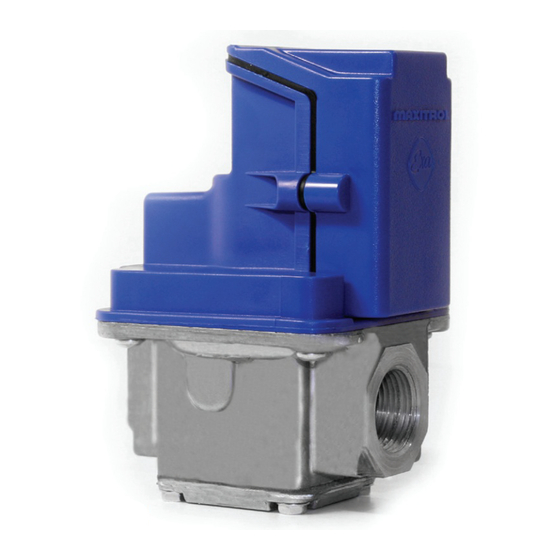
The E40(H), E50(H), E60(H) modulating valves are highly
accurate and precise modulating control valves (see figure 1).
EXA valves provide repeatable process control with minimal
hysteresis throughout the entire range of modulation.
The EXA modulation system's high fire setting and low fire
setting are user programmable.
The EXA modulating valve series has a built-in digital controller
that provides a seamless interface with a process controller.
The valve has two (2) buttons and a communication LED for
the user interface. The buttons are used to set high and low fire
settings (see figure 4, page 4).
The valve has full open and full close (not gas tight) mechanical
limits. The user can program settings that are within the valve's
mechanical limits. This added dimension for sizing and applying
the valve is an important feature. It allows the valve to be set
up for an entirely different net output characteristic (dependent
upon supply pressure) (see table 1, page 2).
There are six (6) electrical connections on the EXA valve. Two
(2) are for power, two (2) are for the control signal, and two (2)
are for position feedback (see figure 2, page 2).
© 2019 Maxitrol Company, All Rights Reserved.
PATENT PENDING
Figure 1: EXA Modulating Valve Series
SPECIFICATIONS
Maximum Inlet Pressure: 5 psig
NOTE: Up to 10 psig available, consult Maxitrol Company.
Power Requirements: 24 VAC/DC +/- 10% 50/60 hz
NOTE: The E40H, 50H, 60H use half-wave rectifiers.
When using a single transformer for powering the E40H,
50H, 60H and devices with half-wave rectifiers, the
common for each must be connected to the same leg
of the transformer. Control signal devices with full-wave
bridge rectifiers require a separate transformer.
See "Power Supply Compatibility" bulletin.
Maximum Current Draw: 200mA
Temperature Limits: -40ºF to 150ºF operating
Control Signal (user selectable): 0-10 VDC, 2-10 VDC,
0-20 mA, 4-20 mA; 100KOhm Input Impedance
Mounting: Multipoise
Gases: Suitable for natural, manufactured, mixed gases,
liquefied petroleum gases, and LP gas-air mixtures.
Certifications:
EMC (EN 61000:2001)
Immunity (EN 61000-6-2:2001)
Emissions (EN 61000-6-4:2001)
UL Recognized
Enclosure: IP40
Electrical Connection: UL310
Sizes:
E40: 3/8", 1/2" NPT or Rp ISO 7-1
E50: 1/2", 3/4" NPT or Rp ISO 7-1
E60: 3/4", 1" NPT or Rp ISO 7-1
1
© 2019 Maxitrol
Advertisement

Related Manuals for Maxitrol EXA E40 Series

Summary of Contents for Maxitrol EXA E40 Series
- Page 1 OEM and with Maximum Inlet Pressure: 5 psig all applicable government codes and regulations, e.g. NOTE: Up to 10 psig available, consult Maxitrol Company. plumbing, mechanical, and electrical codes and practices. These instructions do not supersede OEM’s installation or Power Requirements: 24 VAC/DC +/- 10% 50/60 hz operating instructions.
- Page 2 Pin 2 Connection: TYCO MTA-100 or EQ. NOTE: Optional pre-wired connector for control signal/power/ feedback available. Contact Maxitrol Customer Service for details and availablity. © 2019 Maxitrol Figure 2: EXA Modulating Valve Series Connections © 2019 Maxitrol Company, All Rights Reserved.
- Page 3 (102) (122) (26) (54) (94) (61) (61) EXA50 (110) (140) (34) (87) (94) (84) (61) EXA60 (117) (153) (39) (105) (105) (100) (61) © 2019 Maxitrol Figure 3: EXA Modulating Valve Series Dimensions © 2019 Maxitrol Company, All Rights Reserved.
- Page 4 5 minutes of inactivity. © 2019 Maxitrol Figure 4: EXA Modulating Valve Series Adjustment Controls Maxitrol Company www.maxitrol.com 23555 Telegraph Rd., P.O. Box 2230 © 2019 Maxitrol Company, Southfield, MI 48037-2230 U.S.A. All Rights Reserved. EXA_X1_MS_EN_06.2019...