Advertisement
Quick Links
Techno
Inc.
CNC Router Systems
IMPORTANT! READ THIS SETUP THOROUGHLY
BEFORE RUNNING THE MACHINE. HAVE A LICENSED
E L E C T R I C I A N
CONNECTIONS BASED ON YOUR LOCAL CODES.
This document provides information on how-to setup the LC Series
CNC Routers. More detailed documentation is on the Techno CD-ROM.
All manuals should be read and understood for proper operation of
the machine. These setup instructions contain additional reference
documentation keep all information together.
LC SERIES SETUP INSTRUCTIONS
i.
Minimum System Requirements
I.
UNPACKING THE MACHINE
II.
PCI INTERFACE CARD
III.
WIRING THE AC SPINDLE INVERTER
IV.
TECHNO CNC G-CODE INTERFACE
V.
INSTALL TECHNO CNC INTERFACE
VI.
SCALE FACTOR SETUP
VII.
TOUCHPAD SETTINGS
VIII.
E-STOP START STOP BOX
IX.
USING THE VACUUM TABLE
APPENDICES
A.
COLLETING GUIDELINES
B.
MACHINE MAINTENANCE
C.
ADDITIONAL RESOURCES
i. Minimum System Requirements
· PC with 800Mhz Pentium 3 Processor, 2 GB Memory,
256 Ram, CD-ROM
· Windows 98, ME, 2000, XP or Vista*
· Two Available PCI Slots
*If Vista PC Operating System of choice, Techno Technical
Support will provide required instructions to accommodate
software compatibility.
HTT04810809
Tel: 516/328-3970 · Web: http://www.technocnc.com · E-mail support@technocnc.com
In Business Since 1986
P E R F O R M A L L
LC SERIES BASIC
SETUP INSTRUCTIONS
E L E C T R I C A L
1
Advertisement

Related Manuals for Techno LC Series

Summary of Contents for Techno LC Series
- Page 1 E L E C T R I C A L CONNECTIONS BASED ON YOUR LOCAL CODES. This document provides information on how-to setup the LC Series CNC Routers. More detailed documentation is on the Techno CD-ROM. All manuals should be read and understood for proper operation of the machine.
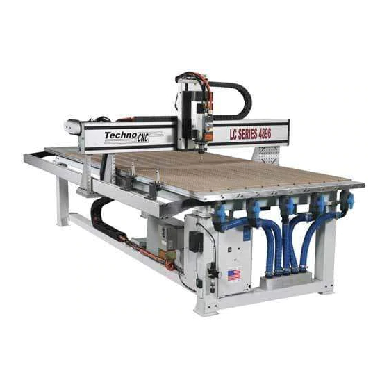
- Page 2 CNC Router Systems I. UNPACKING AND MACHINE IDENTIFICATIONS DIAGRAM 1: Top View of Machine All Techno machines are shipped assembled and secured to Front of Machine a wooden pallet. If your machine was shipped disassembled in any way please refer to the Reassembly Instructions provided with your machine.
- Page 3 Techno LC SERIES BASIC Inc. SETUP INSTRUCTIONS In Business Since 1986 CNC Router Systems II. INSTALLING SERVO PCI INTERFACE CARD PICTURE 3: PCI Interface Card & SCSII Cable Refer to computer manufacturer’s manual for the accessibility and location of the PCI Slots. Install the PCI Interface Card before the software.
- Page 4 Techno LC SERIES BASIC Inc. SETUP INSTRUCTIONS In Business Since 1986 CNC Router Systems WARNING: ALL WIRING AND ELECTRICAL SETUP PICTURE 5: AC Spindle Motor Inverter MUST BE COMPLETED BY A LICENSED ELECTRICIAN. FAILURE TO DO SO MAY CAUSE DAMAGE TO YOUR MACHINE.
- Page 5 When asked for “optional search locations” choose your computer’s CD drive. STEP 3: Click on Setup Techno CNC Interface. KEEP THE TECHNO CD IN A SAFE PLACE, IT CONTAINS ADDITIONAL DOCUMENTATION (PDF FILES). SCREEN CAPTURE 2: Main Menu V. SCALE FACTOR INTERFACE SETUP STEP 1: Start the Techno CNC Interface.
- Page 6 E-Stop is still pushed in. The settings for the E-Stop Start/Stop Box need to be entered and/or confi gured in the Techno CNC Interface prior to using the machine. STEP 1: F r o m t h e M a i n M e n u , g o t o S e t u p >...
- Page 7 If the test passes, you should get the message: “Remote test passed.” If the test fails, repeat. If test fails again, turn power off, check all connections and call Techno Tech Support for further assistance. PICTURE 9: Power Disconnect Switch VIII.
- Page 8 Techno LC SERIES BASIC Inc. SETUP INSTRUCTIONS In Business Since 1986 CNC Router Systems PICTURE 11: 3-Phase Motor Starter Box STEP 3: Insert the AC Power (220 or 440VAC) cable through the knockout hole and connect it to L1, L2, and L3 as specifi ed in the manufacturer’s manual.
- Page 9 PICTURE 16: Filter-Vacuum Hose Conn. PICTURE 17: Rubber Plug in Vac Table USING THE VACUUM HOLD-DOWN The Techno Vacuum Table is very effective in “holding down” parts to be routed. For this method to work well, simple procedures need to be followed.
- Page 10 “hold-down” capacity to your defi ned work area. Each valve controls two rows of vacuum table extrusions. Use Techno’s line of fi xturing accessories (cam clamps, clamp bars, toggle clamps, t-nuts and more) to secure odd-shaped items.
-
Page 11: Colleting Guidelines
Techno LC SERIES BASIC Inc. SETUP INSTRUCTIONS In Business Since 1986 CNC Router Systems APPENDIX A - COLLETING GUIDELINES COLLETING GUIDELINES WRONG! WRONG! RIGHT! The picture above is how your collet nut assembly should look: the end of the collet This picture shows an improper assembly. - Page 12 Techno LC SERIES BASIC Inc. SETUP INSTRUCTIONS In Business Since 1986 CNC Router Systems APPENDIX B - LUBRICATION SPECS. LUBRICATION SPECS. FOR LC / LCP / LCX SERIES MACHINES Y-Axis (Long Axis) – THK Products Grease: Lithium-based grease (JIS NO. 2) or Urea-based Grease (JIS No.
- Page 13 Techno LC SERIES BASIC Inc. SETUP INSTRUCTIONS In Business Since 1986 CNC Router Systems APPENDIX B - LUBRICATION SPECS cont. PICTURE 1: Ball Screw Grease Fitting LC/LCP/LCX SERIES LUBRICATION MAINTENANCE For regular work loads, machine maintenance is required at least once a month.
-
Page 14: Appendix C - Additional Resources
Examples of both are pictured to the right. Record the serial number and have readily available when contacting Techno. TO REORDER VACUUM SUPPLIES: Call Techno Today at: 516-328-3970 ITEM PART NUMBER Rubber Plugs H91X30-PL006-001 Foam Rubber Gasketing...
Need help?
Do you have a question about the LC Series and is the answer not in the manual?
Questions and answers