Advertisement
Quick Links
WARNING: DO NOT OPERATE THIS MACHINE WITHOUT PROPER
TRAINING! Improper or unsafe operation of the machine will result
in personal injury and/or damage to the equipment.
For Support Visit· support.technocnc.com or Call: (631) 648-7481
HDS User Manual
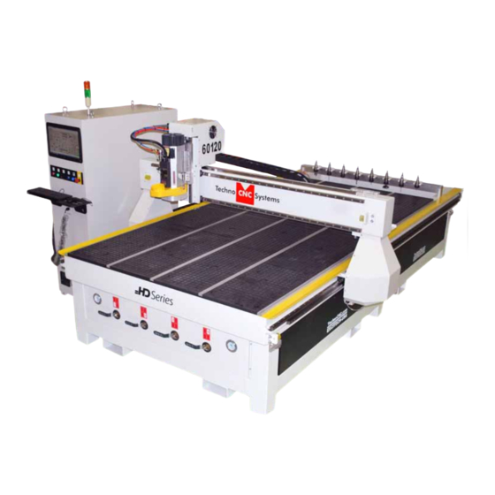
This manual will provide unpacking, maintenance, and user
guide for running the Techno HDS Series CNC Router.
It is suggested that the operator keep this manual by the
machine. This will provide the most important information
pertaining to the operation of this machine.
(HTT06291133)
©2017 (05/08/2017)
1
Advertisement

Related Manuals for Techno HDS Series

Summary of Contents for Techno HDS Series
- Page 1 (HTT06291133) HDS User Manual This manual will provide unpacking, maintenance, and user guide for running the Techno HDS Series CNC Router. It is suggested that the operator keep this manual by the machine. This will provide the most important information pertaining to the operation of this machine.
-
Page 2: Table Of Contents
(HTT06291133) HDS User Manual TABLE OF CONTENTS I..General Installation Instructions. 1.1 Forklift guide and unpacking instructions......Page 3 1.2 Safety Instructions......Page 4 1.3 Correct Colleting......Page 5 1.3.5 Toolstand 1.3.6 Spindle Warmup ......Page 6 1.4 Electrical and Pneumatic connections...... - Page 3 (HTT06081112) Tel: 631-648-7481 • Email: support@technocnc.com FORKLIFT GUIDE I. UNPACKING AND MACHINE IDENTIFICATIONS All Techno machines are shipped assembled and secured to a wooden pallet. Rear of Machine Unpack all items that shipped with your machine. Check the items against the packing slip to be sure nothing was left out.
-
Page 4: Safety Instructions
PREVENT FIRE HAZARDS by using the proper feeds, speeds, and tooling while operating your Techno machine. For example, setting feeds and speeds too low and/or using dull tool bits creates friction at the material. The friction generates heat which can result in a fire that can be drawn through the vacuum table or dust collector without warning. -
Page 5: Correct Colleting
(HTT06291133) HDS User Manual 1.3 Correct Colleting: Read these instructions thoroughly BEFORE operating machine. WARNING! THE SPINDLE WILL BE DAMAGED IF UNBALANCED EQUIPMENT IS USED. AIR SUPPLY MUST BE FILTERED AND DRY. For Support Visit· support.technocnc.com or Call: (631) 648-7481... -
Page 6: Spindle Warmup
(HTT06291133) HDS User Manual 1.3.5 Tool Stand Diagram - Proper Placement Read these instructions thoroughly BEFORE operating machine. 1.3.6 — HSD Spindle Warmup Read these instructions thoroughly BEFORE operating machine. USE AND ADJUSTMENT PREHEATING HSD S.p.A. uses high-precision angular contact bearing pairs, pre-loaded and lubricated for life with special grease for high speeds. -
Page 7: Electrical And Pneumatic Connections
Improper electrical connections can result in damage to the equipment, fire and death. 1.4 Electrical and Pneumatic connections. The Techno HDS series machine is powered by three phase 220 volts. The amperage requirements for this machine are 40 amps. 1.4.1 When the machine has been unpacked, it will be necessary to attach the keyboard shelf to the front of the machine. - Page 8 (HTT06291133) HDS User Manual WARNING: Ensure that all electrical connections are carried out by a qualified electrician. Improper electrical connections can result in damage to the equipment, fire and death. 1.4.4 Attach the three phases and the earth to the connections shown in fig 1.4.4.
-
Page 9: Vacuum Pump Connections
(HTT06291133) HDS User Manual WARNING: Direction of Rotation is critical. Briefly start motion and check rotation (arrow on casing). Exchange phases if rotation is incorrect. IF YOU RUN THE PUMP/BLOWER CONTINUOUSLY IN THE WRONG DIRECTION, THE VANES WILL BE DAMAGED 1.5 Vacuum Pump connections You will need to have an electrician connect AC power Take the silver connector from the Starter Box and connect... -
Page 10: Start Up Procedure
(HTT06291133) HDS User Manual Section II: Machine Start-Up | Screen Functionality 2.1- Start up Procedure. Fig 2.1.2 2.1.1 Turn the Main power switch to the ON Position. 220 Volts should have been attached to this switch by an electrician. Fig 2.1.1 Power Power OSAI... - Page 11 (HTT06291133) HDS User Manual 2.1.4 Software start up. Once the PC has started, the Boot Controller software will start automatically. If it does not, double click on the Boot Controller Icon (It looks like a rocket ship.) on the desktop. If no text appears in the box, after 30 seconds, check that the light for the controller is on and that the network cable from PC to Osai controller is connected.
- Page 12 (HTT06291133) HDS User Manual 2.1.5 Interface Starts: The Techno interface screen will now open. There will be a warning message saying Emergency Stop Active. Click on the E-stop Reset Button to remove this warning. The Axis not referenced error will appear.
-
Page 13: Screen Callouts
(HTT06291133) HDS User Manual 2.2 Screen Callouts Above is the main screen of the Techno HDS interface. To help understand the functions of the buttons they will be broken down into the following categories. A- Jogging functions. B-Homing Functions. C-Pneumatic and Electrical Controls. - Page 14 (HTT06291133) HDS User Manual A-Jogging Functions The sections highlighted below are the Jog controls of the interface. The machine will not move unless a jog mode is selected. Click on the button beside the text to select a mode. A - Handwheel: In this mode, the machine will operate via the MPG/Handwheel.
- Page 15 (HTT06291133) HDS User Manual B-Homing Functions The sections highlighted below are the Homing Functions of the interface. A - Home All: Sends the machine to the home position. (Absolute XYZ = 0). The Z axis will first move up to its limit, then the X and Y axes will move simultaneously. B - SINGLE AXIS HOME: When this button is left clicked, each axis can be homed separately. When the button is active, the user then clicks on the arrow key for the axis to be homed to enable the operation.
- Page 16 (HTT06291133) HDS User Manual C-Pneumatic and Electrical Controls The sections highlighted below are the buttons that control the pneumatic and electrical outputs for the controller. A - Shroud Down: This button will raise or lower the dust shroud on the spindle. B - Pins Up: This button will raise or lower the pop-up pins on the sides of the table.
- Page 17 (HTT06291133) HDS User Manual D-Menu Screens The sections highlighted below are the Menu Screen options of the interface. The user can switch to these screens by clicking on the corresponding button. A - Offsets: Opens the Offset Menu. In this menu the user can save multiple offsets/origins and apply them to the coordinate system.
- Page 18 (HTT06291133) HDS User Manual E-Coordinate System The section highlighted below is the Coordinate System. A - XYZ Coordinates: This displays the location of the machine. If the Origin No is zero,the numbers displayed are the distance from the Home position (Absolute XYZ = 0). If there is an Origin Number active, the numbers displayed are the distance from that origins zero position.
- Page 19 (HTT06291133) HDS User Manual F-Origin Functions The sections highlighted below contain the Origin functions of the interface. A - APPLY ORI 1: Left clicking on this button activates Origin 1 for the coordinate system. B - GO TO XY0 ORI 1: Left clicking on this button moves the Z axis to the home position and the XY axes to the X-zero, Y-zero for Origin 1.
- Page 20 (HTT06291133) HDS User Manual G-Save Origin Menu When the Save Origin button is clicked on the main screen, this screen will open. This screen provides a reminder to identify the tool in the tool holder before saving an origin. A - Warning Message: This screen This gives the user instructions on how to save an origin correctly.
- Page 21 (HTT06291133) HDS User Manual H-Spindle and Coolant Control The section highlighted below allows manual control on the Spindle and Coolant. A-Spindle On/Off : Pressing the button beside On will turn the spindle on, pressing the button beside Off will turn the spindle off @ rpm of 6000. B-AUX On/Off : Pressing the button beside On will turn the coolant on, pressing the button beside Off will turn the coolant off.
- Page 22 (HTT06291133) HDS User Manual I-Load G-Code File A - G-code File: Pressing this button will open the G-code file folder, allowing the user to activate or deactivate a G-code file. For Support Visit· support.technocnc.com or Call: (631) 648-7481...
- Page 23 B - STEP MODE: When this button active, the G-code file will run in Step mode. C - Edit: Left clicking on this button will open the file directory allowing the user to edit the files in a text editor. D - Preview: Left clicking on this button will open the file directory allowing the user to preview the G-code file in the Techno Previewer. E - CYCLE START: Pressing this button will start the active G-code file, in either Step or Auto mode. If no mode is selected then nothing will happen. Cycle start will also carry out commands in MDI mode. F - HOLD: Pressing this button will pause the operation that is in progress. Releasing hold and pressing Cycle Start will continue the operation.
- Page 24 (HTT06291133) HDS User Manual K-Tool Menu When Tool is clicked on the main menu, the screen below will open up. In this screen tool lengths can be learned, tools identified and changed automatically. A - Tool Offset Preset: This section allows the user to manually enter tool offsets. B - CHANGE TOOL: Left clicking on one of these buttons will make the machine pick up the corresponding tool number.
- Page 25 (HTT06291133) HDS User Manual L-Offset Menu When Offset is clicked on the main menu, the screen below will open. In this screen multiple offsets can be saved and recalled. A - ACTIVATE ORIGIN: Left clicking on these buttons will activate the corresponding Origin. B - ORIGIN SET/SAVE ORIGIN: Left clicking on this will open the Origin Preset screen.
-
Page 26: File System-Network
HDS User Manual Section 2.3 File System | Network System The PC is connected to the OSAI controller by an ethernet cable. The Techno interface communicates in real time with the OSAI controller via the ethernet cable to allow jogging and other manual functions. In order to run G-code files to the OSAI controller, they must be copied onto the OSAI controllers hard drive. -
Page 27: Jogging The Machine
(HTT06291133) HDS User Manual Section III: Operating Tutorials 3.1 Jogging the machine The machine has three jog modes: Click on a • Handwheel: box to enable In which the machine is controlled by the handwheel / manual pulse Handwheel generator on the side of the machine. Control. - Page 28 (HTT06291133) HDS User Manual MDI mode stands for Manual Data Input. Activate this mode by clicking the icon in the Jog box. MDI. When this mode is selected a Test box will appear. G-code commands can be entered in this box, then clicking Cycle Start will run the command. G0 X10Y10 in the box then Cycle start will move the machine to X10 Y10 M3 S18000 will turn on the spindle at a speed of 18000rpm M5 will turn off the spindle.
-
Page 29: Learning Tool Lengths
Learning Tool Locations section of the appendix. To learn tool lengths. Click on Tool in the main screen of the Techno interface. Warning take note of the T.OFFSET number. If it tries to return a tool to an occupied tool location, it can cause damage to the tool stands. - Page 30 (HTT06291133) HDS User Manual 3.2 Learning Tool Lengths (Continued) Tool lengths will record how long the tool is in the holder and record the offset value. This will allow multiple tools to be used in a single file. Identify or Change Tools by pressing these buttons.
-
Page 31: Saving An Origin | Setting Xyz Zero Position
(HTT06291133) HDS User Manual 3.3 Saving An Origin | Setting XYZ zero position When setting an origin, make sure the correct tool is in the chuck and this tool has been identified. The T.OFFSET box in the top right hand side of the screen should be 1.1 or 2.2, etc ,for whatever tool is in the chuck. If the T.OFFSET box only reads one digit, the tool must be identified in the Tool screen. - Page 32 (HTT06291133) HDS User Manual The Save Origin screen will open, and a reminder to load the tool number will appear. Click the number of the tool that is in the spindle, then click ORI SET. Enter the Origin Number on top and zero in the XYZ boxes.
-
Page 33: Preparing A G-Code File
Folders can be copied in to the programs folder, but make sure the file G600 is in the same folder as your file. This data must be in the G-code file. If the correct post to Techno Osai HDS machine is used in the CAM package, then it will be entered automatically. - Page 34 (HTT06291133) HDS User Manual 3.4: Preparing a G-Code File (Continued) End of File: (Spindle Off) (Dust shroud up) (File end) So the start of a typical file will look like this. M143 G600 (UAO,01) T1 M6 M3 S18000 (DLY,05) Then the customers G-code. For Support Visit·...
-
Page 35: Running A G-Code File
(HTT06291133) HDS User Manual 3.5 Running a G-Code File Click on G-CODE File to access the file menu. Locate the File you want to load. When loading a new file Left click on the file. click Deactivate to remove the old file, before you click - Click Activate to load it to the machine. - Page 36 (HTT06291133) HDS User Manual 3.5 Running a G-Code File (Continued) The file name will now appear on the top right of The file will now run. the screen. You are now ready to run the file. - Pressing HOLD will pause the machine. - Pressing CYCLE START will continue the file. To run the file. -Ensure that the Origin and the Tool offsets are set.
-
Page 37: Machine Origin,Working Origin, & Offsets
(HTT06291133) HDS User Manual 3.6 Machine Origin, Working Origin and Offsets Machine Origin: When the machine goes to the home position, the coordinate system is set to zero. This is the machine origin. Machine origin is a reference position from which Tool locations, lengths and saved offsets can be recalled. -
Page 38: Using Block To Block Function
(HTT06291133) HDS User Manual SECTION IV: Advanced Tutorials 4.1 Using Block to Block Functions Block to block function will allow a particular section of a G-code file to be run. For this function to operate, the G-code file must have line numbers in the following manner: N100 G0X35Y10 N101 G1X35Y0 When Block to Block is clicked, the user will be asked to enter the Starting block Number and the ending block number. -
Page 39: Mem Search
(HTT06291133) HDS User Manual 4.2 Mem Search Mem search will allow you to find the last reset point in the file currently activated. If you press RESET while running a file, you can continue from that point by pressing MEM S. The G-code will be searched for the last break point, and once it has been found, pressing CYCLE START will continue from that point. 4.3 Return to Profile. If the user presses HOLD while a file is running and jogs off the part, when they try to restart, a “Not on part profile error”... -
Page 40: Setup Parameters
(HTT06291133) HDS User Manual 4.4. Setup Parameters Certain parameters for a G-code file can be changed from the Setup window in the interface. Any changes here are cleared when RESET is pressed in the main screen. Click on Setup and the drop down menu will appear. - Page 41 (HTT06291133) HDS User Manual Dynamic Parameters will allow adjustment in canned drilling cycles. See the Osai G-code manual for more details on canned cycles. Dynamic Limits will effect the smoothness of the machine. See the Osai Amp manual for more details on these values. For Support Visit·...
- Page 42 (HTT06291133) HDS User Manual Program Setup will allow adjustments to the G-code file. - Block delete will delete a highlighted part of a G-code file. - Feedrate bypass will override the programmed feedrates and use the percentage feed on the main screen. - Disable program scroll will stop every line of G-code appearing on the screen.
- Page 43 (HTT06291133) HDS User Manual Probe Setup controls the way the tool offsets are learned and should not be adjusted. Set Accuracy will adjust the arc tolerance for circles and curves in the file. See the Osai Amp and Osai G-code manual for more information For Support Visit· support.technocnc.com or Call: (631) 648-7481...
-
Page 44: Backing Up Parameters
(HTT06291133) HDS User Manual 4.5 Backing Up Parameters. The parameters of the Amp and PLC should be backed up before any adjustments are made to them. Restart the controller in Setup Mode. Select Boot, then Restart, then pick Setup from the Mode menu. Once in Setup Mode, click on the Security Icon to enter the security window. - Page 45 (HTT06291133) HDS User Manual Click on Backup to select the backup option Click on Browse and pick / create a suitable folder to save the backup, enter a suitable file name for the backup and click Save. For Support Visit· support.technocnc.com or Call: (631) 648-7481...
- Page 46 (HTT06291133) HDS User Manual Once complete, close the Security Check the box beside All the control window, and reboot the controller and click Start to begin the backup. in Normal mode. To Restore a saved backup, just reboot in setup mode again, and select Restore to load the saved settings. For Support Visit·...
- Page 47 The rails do not need to be lubricated as often as the rack. Once a month should be sufficient. X axis Recommended Lubricants. Lithium Based Grease: • Alvania Grease No. 2(Shell) or Equivalent. • Techno Part No. H90Z00-8670T8 Oil: • Vactra No. 2s(mobile) • Tonner Oil or Equivalent. Z axis • Techno Part No. H90200-LUBE002 Oil and Grease Kit: •...
-
Page 48: Hsd Aggregate Tool Setup
(HTT06291133) HDS User Manual Section VI: Appendix 6.0 HSD Aggregate Tool Setup. (Diagram 2. The current HSD Aggregate Tool aggregate angle.) Please follow these instructions carefully to properly install the HSD aggregate on your machine. (Diagram 1. The pin must be in this position in the tool holder.) Diagrams 2 and 3 illustrate how to adjust the angle of the aggregate cutting tools. - Page 49 (HTT06291133) HDS User Manual How to Set Up Tool Offsets with Aggregate Tools Click “Utility.” Click “Table Editor.” Click here Click here for tool for English lengths. units. In the offset screen, you will enter the following values for the aggregate offset. Center NOTE: Right-hand and...
-
Page 50: Drill Lengths On The Hds Drill Bank Machine
(HTT06291133) Addendum: HDS User Manual HDS Drill Bank Machine 6.1 Addendum: HDS Drill Bank Machine How to set up Drill Lengths on the HDS Drill Bank Machine. Because of the addition of the Drill Bank, we need to properly tell the software the length of the drill bits in the bank. - Page 51 (HTT06291133) Addendum: HDS User Manual HDS Drill Bank Machine 6.1 Addendum: HDS Drill Bank Machine 3. Once the “Table Editor” opens up in a new window, we need to select “Tool Lengths”. Click on the “Tool Offset” button shown below to display the tool length table.
- Page 52 (HTT06291133) HDS User Manual 6.1 Addendum: HDS Drill Bank Machine Addendum: HDS Drill Bank Machine 5. Depending on the length of the drills, you must input 1 of 3 lengths. See the table below. Drill Tool Length in mm Z-Offset 57mm -8.55352 70mm...
- Page 53 (HTT06291133) HDS User Manual Addendum: HDS Drill Bank Machine 6.1 Addendum: HDS Drill Bank Machine Offset (Tool #) Z Offset Y Offset X Offset Use AutoTouchoff 1 -1.37339 -8.33738 Use AutoTouch off 2 -1.37339 -8.33738 Use AutoTouch off 3 -1.37339 -8.33738 Use AutoTouch off 4 -1.37339...
-
Page 54: Service And Maintenance Guide
(HTT06291133) HDS User Manual P a g e Service and Maintenance Caution (1) Maintenance shall be performed by qualified personnel. (2) Switch off the main power supply before servicing. If power supply is needed, have qualified personnel operate it. (3) Use genuine replacement parts and components. Linear drive component Maintenance Wipe the linear rails and bearings once a day to assure smooth play free motion. - Page 55 (HTT06291133) HDS User Manual P a g e Electrical Cabinet Maintenance Caution: Switch off the main power supply before servicing. If power supply needed, qualified personnel shall operate it. (1) Clean the cabinet with dust collector once every week. Be careful not to damage or loosen any wire connections.
- Page 56 8) The air needs to be filtered to be free of moisture, oil mist and dust before entering the spindle. 9) ISO30 tool holders and collets should be cleaned weekly. It is recommended to use a rust prohibitor. (Techno p/n: H25XOS-33-21) Other maintenance To ensure longer service life, perform regular maintenance of the parts and components: (1) Check the overtravel limit switches (both software limit switch and mechanical stops) regularly.
- Page 57 (HTT06291133) HDS User Manual P a g e sensitiveness and may fail to give alarm when the machine over travels, which could lead to mechanical crash and damage to the machine. The way to check is to press the switch with hand and see if it gives off alarm.
- Page 58 (HTT06291133) HDS User Manual P a g e Appendix I Daily Maintenance Sheet 29 Trade Zone Drive, Ronkonkoma NY 11779 Office: (631) 648-7481 www.technocnc.com For Support Visit· support.technocnc.com or Call: (631) 648-7481...
-
Page 59: Fault Finding/Error Messages
If not, move the sensor around the cylinder until the light comes on. • If the light will not come on, it will need to be replaced. Syntax Error when loading a There is an unrecognized command in the G-code file. G-code file Use the correct Techno post in the CAM package and output the file again. Error Message Problem Solution 001 EMERGENCY STOP ACTIVE E-stop pushed in. - Page 60 (HTT06291133) HDS User Manual P a g e Appendix II Common Errors and Solutions Driver Error Codes 29 Trade Zone Drive, Ronkonkoma NY 11779 Office: (631) 648-7481 www.technocnc.com For Support Visit· support.technocnc.com or Call: (631) 648-7481...
- Page 61 (HTT06291133) HDS User Manual P a g e List of Alarms for VFD 29 Trade Zone Drive, Ronkonkoma NY 11779 Office: (631) 648-7481 www.technocnc.com For Support Visit· support.technocnc.com or Call: (631) 648-7481...
- Page 62 (HTT06291133) HDS User Manual P a g e 29 Trade Zone Drive, Ronkonkoma NY 11779 Office: (631) 648-7481 www.technocnc.com For Support Visit· support.technocnc.com or Call: (631) 648-7481...
- Page 63 (HTT06291133) HDS User Manual P a g e 29 Trade Zone Drive, Ronkonkoma NY 11779 Office: (631) 648-7481 www.technocnc.com For Support Visit· support.technocnc.com or Call: (631) 648-7481...
-
Page 64: Becker Vacuum Pump Manual
(HTT06291133) HDS User Manual VTLF 2.200 Betriebsanleitung Driftsinstruks Operating Instructions Driftsinstruktioner VTLF 2.250 Instructions de service Käyttöohje Driftsvejledning Istruzioni d’uso Instrukcja obsługi Handleiding Kezelési útmutató Instrucciones para el manejo Návod k obsluze Manual de instruções 98/37 EG Naudojimosi instrukcija Navodilo za uporabo 2006/95 EG Kasutusjuhend Návod na obsluhu... - Page 65 (HTT06291133) HDS User Manual Mat.Nr. XXXXXX ENXXXX 3 Mot. XXXXXXXX NoUD XXXXXX 50 Hz 60 Hz XXKW XXKW XXX-XXX / XXX-XXX XXX-XXX / XXX-XXX XX-XX / XX-XX XX-XX / XX-XX 0.XX-0,XX 0.XX-0,XX XXXX-XXXX /min XXXX-XXXX /min XX kg MAX. 6x /h =OFF L2 L1 L3 I >...
- Page 66 (HTT06291133) HDS User Manual < 2m “ 2m...3m “ / 3“ > 3m...10m VACUUM 5 Min =OFF 40 - 200 h www.beckerpumps.com For Support Visit· support.technocnc.com or Call: (631) 648-7481...
- Page 67 (HTT06291133) HDS User Manual VTLF 2.200 VTLF 2.250 VTLF 2.200 VTLF 2.250 x x x F2 (VTLF - SK) D: 218 mm D: 64 mm H: 122 mm H: 120 mm No.: 909512 No.: (2x) 909510 3000 h www.beckerpumps.com For Support Visit· support.technocnc.com or Call: (631) 648-7481...
- Page 68 (HTT06291133) HDS User Manual MAX. MIN. > 41mm < 41mm � → No. 90136701005 (SET) No. 743303 Amblygon TA 15/2 3000 h 2x 10g For Support Visit· support.technocnc.com or Call: (631) 648-7481 www.beckerpumps.com...
-
Page 69: Becker Vacuum Pump Filter Inspection
(HTT06291133) HDS User Manual TLF 2.250-2.500 Internal Filter Inspection -Tools required- Flashlight ATTENTION Author: Mike Ruff Becker Pumps Corp. VISUAL CLUES REGARDING VTLF 2.250 FILTER MAINTENANCE SHOULD NOT ALWAYS BE THE SOLE INDICATOR OF WHETHER A FILTER IS “CLEAN”. THOUGH THE FILTER HAS TREMENDOUS SURFACE AREA, THE DEEP PLEATING OF THE FILTER MAY DISGUISE WHETHER THE FILTER IS CLOGGED. - Page 70 (HTT06291133) HDS User Manual -Remove the internal filter and look for debris- -Check for large debris deposits. This is an indicator that the filter caught the smaller particles- Author: Mike Ruff Becker Pumps Corp. -Use a flashlight on the outside of the filter- Author: Mike Ruff Becker Pumps Corp.
- Page 71 (HTT06291133) HDS User Manual If light cannot be seen on the inside, the filter is clogged and needs replaced. Author: Mike Ruff Becker Pumps Corp. -If you can see light, then blow out the filter using compressed air and replace- •...
-
Page 72: Becker Vacuum Pump Greasing Process
(HTT06291133) HDS User Manual Greasing TLF 2.200-2.360 -Tools required- X1 – 7433050000 (50 gram grease gun) Author: Mike Ruff Becker Pumps Corp. Greasing instructions The greasing instructions can be found on step “P.” in the operation manual sent with each pump. Or they can be found at www.Beckerpumps.com Bearings are to be grease every 3000 –... - Page 73 (HTT06291133) HDS User Manual All new units come with new grease guns. (Found in either of the two places below) Author: Mike Ruff Becker Pumps Corp. GREASING PROCEDURE Author: Mike Ruff Becker Pumps Corp. For Support Visit· support.technocnc.com or Call: (631) 648-7481...
- Page 74 (HTT06291133) HDS User Manual Remove the filter cover by loosening the black hand knobs. Author: Mike Ruff Becker Pumps Corp. Remove the internal filter and replace if needed. Grease fittings are found next to the filter. (Remove the red caps.) Author: Mike Ruff Becker Pumps Corp.
- Page 75 (HTT06291133) HDS User Manual Remove the black cap from the grease gun Author: Mike Ruff Becker Pumps Corp. Prime all new grease guns by placing them at an angle against a hard surface. Pump a few times until the grease is visible at the tip. Author: Mike Ruff Becker Pumps Corp.
- Page 76 (HTT06291133) HDS User Manual Place the grease gun against the push fitting Pump 10x into each bearing (New or dry bearings = 25 times per bearing) Author: Mike Ruff Becker Pumps Corp. Once the pump is ran, the grease will evenly distribute between the rollers and ball bearings.
-
Page 77: Warranty
In no event shall Techno CNC Systems, LLC., be liable for any incidental, consequential, or special damages of any kind or nature whatsoever. Techno CNC Systems, LLC., is in no way liable for any lost profits arising from or connected to this agreement or items sold under this agreement, whether alleged to arise from breach of contract, expressed or implied warranty, or in tort, including, without limitation, negligence, failure to warn, or strict liability.
Need help?
Do you have a question about the HDS Series and is the answer not in the manual?
Questions and answers