
Subscribe to Our Youtube Channel
Related Manuals for Robotnik RB-1


Summary of Contents for Robotnik RB-1
- Page 1 RB-1 MODULAR MOBILE MANIPULATOR Hardware Manual Version 1.0 RBTNK-DOC-161020 Robotnik Automation, S.L.L.
- Page 2 1 61020 RBTNK-DOC- Hardware Manual. RB-1 Modular Mobile Manipulator INDEX 1 Introduction 2 Robot description 2.1 General overview 2.2 Components description 2.2.1 Wheels 2.2.2 Motor Driver 2.2.3 Electrical components 2.2.3.1 DC-DC 2.2.3.2 Fuses & terminal 2.2.4 Control components 2.2.4.1 Embbeded PC 2.2.4.2 Wireless Router...
- Page 3 1 61020 RBTNK-DOC- Hardware Manual. RB-1 Modular Mobile Manipulator 4.1 Back Panel 4.2 Head Panels 5 Comunication diagram 6 Maintenance 7 Basic Drawing...
-
Page 4: Robot Description
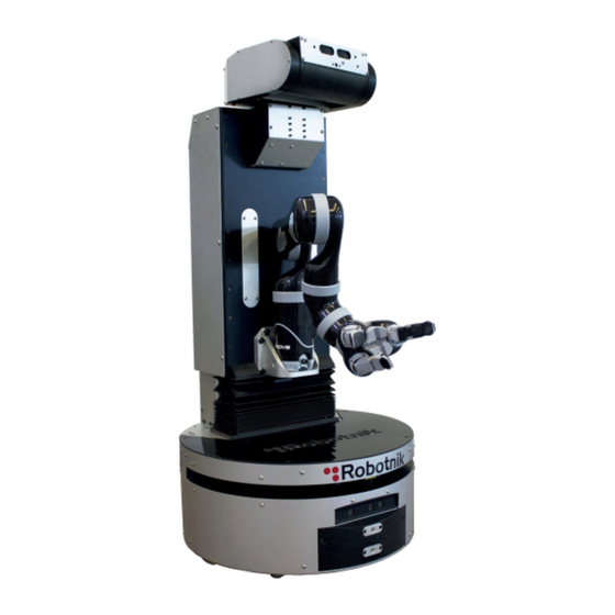
Hardware Manual. RB-1 Modular Mobile Manipulator 1 Introduction This Manual describes the main parts of the RB-1 modular mobile manipulator, as well as how to access to the internal components. Every main piece includes a little description, emphasizing the elements that need a special periodical control and maintenance. - Page 5 RBTNK-DOC- Hardware Manual. RB-1 Modular Mobile Manipulator ● MICO or JACO arm: The RB-1 can incorporate a MICO or JACO arm from Kinova. ● Laser location: Place inside the robot where is possible to install the compatible laser rangefinder describe in the section 2.2.4.1.
-
Page 6: Components Description
RBTNK-DOC- Hardware Manual. RB-1 Modular Mobile Manipulator 2.2 Components description This section describes the components included in the RB-1 modular mobile manipulator. 2.2.1 Wheels The robot has two motor wheels and three omniwheels as it’s shown in the next picture: Figure 3 –... -
Page 7: Motor Driver
Figure 5 – Motor Driver The drivers are programmed at Robotnik with specific a settings for each motor. The serial identifier is the default one (63), but each driver has its own CAN bus identifier (1 and 2). DO NOT change them from one motor to another. - Page 8 1 61020 RBTNK-DOC- Hardware Manual. RB-1 Modular Mobile Manipulator There is a small 5V DC/DC in the electronic box to power the control circuit of the motor drivers, the router and the USB hub. Figure 8- 5V DC/DC 2.2.3.2 Fuses & terminal The fuses terminal is accessible from the outside of the electronic box.
- Page 9 1 61020 RBTNK-DOC- Hardware Manual. RB-1 Modular Mobile Manipulator The robot has two terminals inside, one is in the electronic box and the other is in the torso. The next picture shows where is located the terminal inside the electronic box. The terminal distributes the power to all the components of the electronic box.
-
Page 10: Control Components
1 61020 RBTNK-DOC- Hardware Manual. RB-1 Modular Mobile Manipulator 2.2.4 Control components 2.2.4.1 Embbeded PC The embbeded PC is located inside the electronic box. The main board is an Intel NUC BOXNUC5i7RYH T he computer is . completed with 8GB of RAM and a M.2 HDD. - Page 11 1 61020 RBTNK-DOC- Hardware Manual. RB-1 Modular Mobile Manipulator 2.2.4.2 Wireless Router The wireless router is located inside the electronic box. Figure 13– ASUS RT-N12 The huge 9dB antennas are changed with smaller 5dB antennas Technical Specification ● Wireless Data Transfer Rate: 802.11n: 300Mbps ●...
- Page 12 1 61020 RBTNK-DOC- Hardware Manual. RB-1 Modular Mobile Manipulator 2.2.5 Sensors 2.2.5.1 Pixhawk The Pixhawk is located inside the electronic box. It is used as an IMU (Inertial Measurement Unit) to better estimate the robot position, using the Pixhawk integrated gyroscope and accelerometers.
- Page 13 1 61020 RBTNK-DOC- Hardware Manual. RB-1 Modular Mobile Manipulator 2.2.5.2 Orbbec The Orbbec is located in the front of the base and also in the head of the robot. The Astra 3D cameras are excellent for a wide range of scenarios, including gesture control, robotics, 3D scanning, and point cloud development.
- Page 14 1 61020 RBTNK-DOC- Hardware Manual. RB-1 Modular Mobile Manipulator URG-04LX Indoor Environment Wide Angle: 240° Angular resolution: 0.36º Scanning time: 100 ms Measuring area: 20 to 4095mm Accuracy:60 to 1000mm : ±10mm; 1000 to 4095mm : 1% of measurement Interface: USB, RS232...
-
Page 15: Control Panel
1 61020 RBTNK-DOC- Hardware Manual. RB-1 Modular Mobile Manipulator 2.3 Controllers This section describes where are the controlers of the robot. 2.3.1 Control Panel The robot presents in its back several buttons, indicators and connectors: Figure 16 - Control panel - EMERGENCY STOP... - Page 16 RB-1 Modular Mobile Manipulator 2.3.2 Gamepad The Gamepad used for the manual movements of the robot RB-1 is a Bluetooth Joystick. The NUC board has an internal bluetooth receiver. The two joysticks are used for direction, traction and elevation and there...
- Page 17 1 61020 RBTNK-DOC- Hardware Manual. RB-1 Modular Mobile Manipulator 2.4 Battery The robot receives the power supply from a LiFePO4 battery pack. It is composed of sixteen 3.2V LiFePO4 cells and a protection circuit module. With this set of batteries the robot is able to operate up to 10 hours or more, depending on the robot movements.
-
Page 18: Battery Pack
1 61020 RBTNK-DOC- Hardware Manual. RB-1 Modular Mobile Manipulator There is a 20A fuse (F00) between the plates and the batteries for safety. This fuse is inside the battery pack.. Figure 19- Fuse F00 location Full charging time is around 45-60 minutes for the supplied charger. Do not use other chargers without checking battery specifications. - Page 19 1 61020 RBTNK-DOC- Hardware Manual. RB-1 Modular Mobile Manipulator Figure 21– Power supply connector from the Battery Pack IMPORTANT: Recharge the batteries ASAP if fully discharged. Keeping the voltage low for a long time will greatly reduce the lifecycles. 2.4.2 LiFePo4 Cell...
- Page 20 1 61020 RBTNK-DOC- Hardware Manual. RB-1 Modular Mobile Manipulator 2.4.3 Protection circuit module Figure 23– Protection circuit module 24V BMS 8CELLS 30A Item 8 series balancing guard shield Over charge protection (V) 3.95±0.025 Over charge recovery (V) 3.80±0.05 Over discharge voltage (V) 2.2±0.1 Over discharge recovery (V) Cut load or charge Normal working current (A) 30 Over current protection (A) 60 Internal resistance (m/ohm) <30 Charging balancing current (mA) ...
-
Page 21: Specifications
1 61020 RBTNK-DOC- Hardware Manual. RB-1 Modular Mobile Manipulator 2.5 Charger The Charger supplied is shown in the next picture. The Smart Charger is designed for rapidly charge 29.2V (8 cells) LiFePO4 Battery pack. Figure 24– LiFePo4 Smart Charger IMPORTANT: CHECK POWER SELECTION BEFORE PLUGGING IT Figure 25–... - Page 22 1 61020 RBTNK-DOC- Hardware Manual. RB-1 Modular Mobile Manipulator o Max output current: 10.5A o Continous current: 6.25 A For mor information go to: http://www.meanwell.com/mw_search/PB-300/PB-300,360-E.pdf LED Indicator: ● Red: Constant current & constant voltage state ● Green: Floating state Caution: The charger is designed for indoor use only.
- Page 23 1 61020 RBTNK-DOC- Hardware Manual. RB-1 Modular Mobile Manipulator 3 Accessibility This section describes how to access to the different internal parts of the robot. 3.1 Base To have access to the motors, orbecc camera, laser and the power and motor connectors you have to remove the covers as it’s shown in the following pictures.
- Page 24 1 61020 RBTNK-DOC- Hardware Manual. RB-1 Modular Mobile Manipulator Figure 27 – Front and back cover 3.2 Electronic box To extract the electronic box you have to remove the back and front covers of the base and later follow the instructions of the following pictures:...
- Page 25 1 61020 RBTNK-DOC- Hardware Manual. RB-1 Modular Mobile Manipulator Figure 29 – Electronic box extraction - Step 2 Next picture shows the components locates inside the electronic box. Figure 30 – Electronic box components Last picture shows the real aspec of the interior of the box.
- Page 26 1 61020 RBTNK-DOC- Hardware Manual. RB-1 Modular Mobile Manipulator Figures 31 - Internal view 3.3 Torso To have access to the electronics inside the torso you have to remove the covers as it’s shown in the following pictures. Figure 32 – Torso covers removal...
- Page 27 1 61020 RBTNK-DOC- Hardware Manual. RB-1 Modular Mobile Manipulator Figure 33 – Interior torso components Last picture shows the real aspec of the interior of the torso. Figures 34 - Internal view...
- Page 28 1 61020 RBTNK-DOC- Hardware Manual. RB-1 Modular Mobile Manipulator 3.4 Head To have access to motors of the head you have to remove the covers as it’s shown in the following pictures. Figure 35– Head covers removal 3.5 Battery To remove the battery pack you have to follow the followin steps.
-
Page 29: Back Panel
1 61020 RBTNK-DOC- Hardware Manual. RB-1 Modular Mobile Manipulator 4 Connectivity. This section describes the connectivity present in the robot. 4.1 Back Panel The robot on their back panel has two USB, a HDMI port and two Ethernet ports (WAN and LAN):... - Page 30 1 61020 RBTNK-DOC- Hardware Manual. RB-1 Modular Mobile Manipulator 4.2 Head Panels Figure 38 - Head panel Figure 39 - Molex pinout Voltage 12VDC 5VDC Table 4 – Molex voltage pinout...
- Page 31 1 61020 RBTNK-DOC- Hardware Manual. RB-1 Modular Mobile Manipulator 5 Comunication diagram The following figure shows the communication diagram existing inside the robot. The functionality of the system can be further extended by using the free Ethernet ports and free USB port.
-
Page 32: Maintenance
1 61020 RBTNK-DOC- Hardware Manual. RB-1 Modular Mobile Manipulator 6 Maintenance The following table shows some elements that need maintenance and the periodicity of this maintenance. Often Every 6 month Observations Screws Check they are not loosen. Tires Visual control of the Replace when wear rate. - Page 33 1 61020 RBTNK-DOC- Hardware Manual. RB-1 Modular Mobile Manipulator 7 Basic Drawing Figure 38– External robot drawings...
Need help?
Do you have a question about the RB-1 and is the answer not in the manual?
Questions and answers