Advertisement
Quick Links
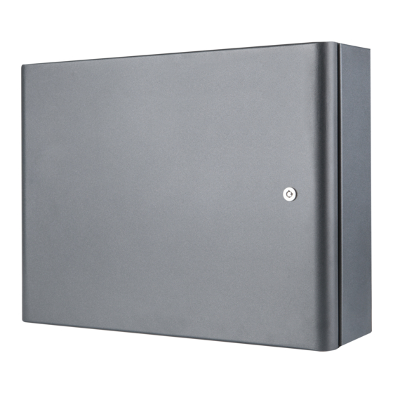
IRIS PS72
Back-up power supply unit for
IRIS addressable fire alarm panel
18
1293
DoP No: 059
1293-CPR-0610
Tested by EVPU
Teletek Electronics JSC
Address: 14A Srebarna Str,
1407 Sofia, Bulgaria
EN 54-4:1997
EN 54-4:1997/AC:1999
EN 54-4:1997/A1:2001
EN 54-4:1997/A2:2006
ATTENTION:
Read carefully this installation Instructions
before installing the device! This manual is
subject to change without notice!
!
Installation
~6kg
IP30
-5°C ÷ +40°C (working)
-10°C ÷ +60°C (storage)
(93 ± 3)% @ +40°C
2
2
0.5mm -2.5mm
ю
Indoor use
Outdoor use
18020959; RevA; 08/2018
IMPORTANT NOTES
• Warning! An appropriate disconnect device shall be provided
as part of the building.
• Switch OFF the main power supply and the battery of the
IRIS panel before installing the IRIS PS72 power supply unit!
• Use only the connection cables supplied with the equipment:
red and black wires for connection to JP4 terminals; white and
grey wires for connection to FLT terminals! Do not shorten or
extending these cables!
• Make all the wiring observing the polarity of the connections
following the presented connection diagrams. If after
powering on the IRIS PS72, the LED "WRONG CONNECTION"
is lighting on, switch off the power supply immediately and
check the connection between the power supply unit of IRIS
panel and terminals JP4 of IRIS PS72!
• If the LED "Hi Resist" for Battery 1 or 2 is blinking it is
strongly recommended to change the batteries immediately!
• The cover is mounted to the box bottom with hinges fixed
with dismountable rivets. The angle of opening of the front
cover must not be greater than 110°!
TECHNICAL SPECIFICATIONS
Main power supply . . . . . . . . . . . 230V~ +10%/ -15%, 0.6A, 4A fuse
Frequency . . . . . . . . . . . . . . . . . 50-60Hz
DC Output:
- Voltage . . . . . . . . . . . . . . . . . 9.9-14.2V
- Max. Current . . . . . . . . . . . . . 7A@1 battery, 14A@2 batteries
Int. resistance of the battery Ri . < 0.3Ohm
Max. battery capacity . . . . . . . . . 2x12V/18Ah
Charger outputs . . . . . . . . . . . . . 13.65V
Color of the box . . . . . . . . . . . . . grey
Dimensions . . . . . . . . . . . . . . . . 430x330x117mm
Max. dimensions of 1 battery . . . 167x181x76mm
!
Installation
Max. 110°!
INSTALLATION INSTRUCTIONS
General Description
IRIS PS72 is a power supply unit designed for back-up power supply of
IRIS addressable fire alarm panel. The power supply is placed into a
metal box suitable for building of a modular structure with the
addressable panel and a second power supply unit. The access to the
main board and the cable connections is secured with a key.
The status of IRIS PS72 is displayed via a LED indication on the main
PCB. The status of the power supply unit can be continuously monitored
with enabling the option "External PSU Check" from the IRIS panel
menus. When the option is enabled the panel will display a fault
message "External Power Supply Fault, Periphery Device 1-PSU" in
case of any trouble with the power supply. The respective trouble of the
power supply is visualized with a blinking LED on the PCB.
At normal operation mode only "OK" green LED is blinking and all other
LEDs are off. In case of main power supply (230V~) loss the "FLT"
yellow LED starts blinking and "OK" green LED is off. In case of trouble
with a Battery 1 and/or 2, the yellow LEDs at sections Batt1 and/or Batt2
are blinking. A detail description of all LED indicators is performed at
Item 2: IRIS PS72 Main Board - see on page 2.
!
Mounting
±1%@20°C, max. 2A
1 - Mounting holes
2 - Openings for
running cables -
on the box bottom,
on the up and
down side*
347 mm
3 - Opening for
running cables
when a few
panels are fixed
in a modular
structure*
4 - Ø 5mm openings
(4 on upside and
4 on downside on
the box bottom) for
fixing the panel to
other boxes from
the same type
* Protected with a
430 mm
metal cap element
Advertisement

Related Manuals for Teletek electronics IRIS PS72

Summary of Contents for Teletek electronics IRIS PS72
- Page 1 JP4 terminals; white and The status of IRIS PS72 is displayed via a LED indication on the main grey wires for connection to FLT terminals! Do not shorten or IRIS PS72 PCB.
- Page 2 IRIS panel occurs. Connect the second FLT terminal of the first IRIS IRIS PS72 to the FLT terminal of the second IRIS PS72 as observing the polarity, and so on. Attention: The FLT Power Supply...
Need help?
Do you have a question about the IRIS PS72 and is the answer not in the manual?
Questions and answers