Table of Contents
Advertisement
Advertisement
Chapters
Table of Contents

Related Manuals for intensity WDC-120G/WK(A)


Summary of Contents for intensity WDC-120G/WK(A)
- Page 1 WIRED CONTROLLER WIRED CONTROLLER MODELO: WDC-120G/WK(A) MODELO: WDC-120G/WK(A) 2nd Generation VRF Wired Controller SERVICE MANUAL SERVICE MANUAL MAN-S-WC120G-1220 MAN-S-WC120G-1220 intensity.mx intensity.mx *imágenes con fines ilustrativos *imágenes con fines ilustrativos...
- Page 2 WDC-120G/WK(A) 202011...
- Page 3 VRF units. For the connections of the VRF units, the user should refer the respective Installation Manuals, Owner’s Manuals and Service Manual or contact with Intensity Technical Support Engineer for smooth resolution of the problem.
- Page 4 WDC-120G/WK(A) 202011...
- Page 5 WDC-120G/WK(A) CONTENTS Part 1 WDC-120G/WK(A) Introduction…………………………..…...………………….…03 Part 2 WDC-120G/WK(A) Installation & Commissioning………….…………….…...15 Part 3 WDC-120G/WK(A) Functions............…...39 Part 4 WDC-120G/WK(A) Troubleshooting……….……………………..………...………81 Part 5 WDC-120G/WK(A) Appendix………………………………………….………………..87 202011...
- Page 6 WDC-120G/WK(A) 202011...
-
Page 7: Table Of Contents
WDC-120G/WK(A) Part 1 Introduction 1 GENERAL ............................. 4 1.1 Safety Precautions ......................... 4 1.2 Attachments with the Box ......................6 2 INTRODUCTION ........................... 7 3 DIMENSIONS ............................8 3.1 Front and Side Views ........................8 3.2 Back View ............................9 4 MODES OF CONNECTION ........................ -
Page 8: General
Improper installation or attachment of equipment or accessories could result in electric shock, short-circuit, leaks, fire or other damage to the equipment. Only use accessories, optional equipment and spare parts made or approved by Intensity. WARNING Make sure installation, testing and applied materials comply with the applicable legislation. - Page 9 WDC-120G/WK(A) WARNING After finishing the electrical work, confirm that each electrical component and terminal inside the electrical cabinet is securely connected. Make sure all covers are closed before starting up the units. Installation Safety WARNING Do not install the WDC-120G/WK(A) near areas of electromagnetic interference or next to base station. Locate the WDC-120G/WK(A) away from sources of steams, possible flammable gas leaks, heat or sulfurous gases.
-
Page 10: Attachments With The Box
MODELO: WDC-120G/WK(A) MODELO: WDC-120G/WK(A) SERVICE MANUAL SERVICE MANUAL MAN-S-WC120G-1220 MAN-S-WC120G-1220 intensity.mx intensity.mx *imágenes con fines ilustrativos *imágenes con fines ilustrativos Cross round head wood mounting screw (dia 4 mm*20mm) *3 Cross round head mounting screw (M4*25mm)*2 Plastic Expansion pipe (dia 4.2mm*28.5mm) -
Page 11: Introduction
WDC-120G/WK(A) 2 Introduction WDC-120G/WK(A) is a power line communication based wired controller which aims to fulfill the needs of group control for application scenarios such as a big hall where all the VRF indoor units are required to operate in the same fashion in all the circumstances. -
Page 12: Dimensions
WDC-120G/WK(A) 3 Dimensions In this section, we will discuss the dimensional aspect of the WDC-120G/WK(A) controller. We will have a look at what are the various length, breadth and height for this controller. The front view, side view and top view of this controller have been discussed in the below sections 3.1 Front and Side Views (Unit: mm) -
Page 13: Back View
WDC-120G/WK(A) 3.2 Back View (Unit: mm) 202011... -
Page 14: Modes Of Connection
2-way communication in this case. There will be only one-way communication where in the information flows from the wired controller to the indoor unit. This type of communication is not suggested from Intensity end. Important Point: There is no polarity between X1 and X2 ports... -
Page 15: Wiring Specifications
WDC-120G/WK(A) 5 Wiring Specifications Important points: 1. The switch box and control wire for 2nd generation DC IDU are not attached. 2. Do not touch the remote controller main board. Shielded, 2-conductor or 4-conductor for connection through Wiring Type X1/X2/D1/D2 ports Shielded, 4-conductor for connection through ABCDE ports Wiring Size AWG 20... -
Page 16: Multiple Connection Methods
WDC-120G/WK(A) 6 Multiple connection methods The various methods of using this wired controller and various advantages and benefits of using a particular mode of communication have been enlisted in detail below: 6.1 One Wired Controller for one Indoor Unit In this scenario, the wired controller’s X1X2 port connects with the X1X2 port of the indoor unit. There is no polarity between the X1 and X2 ports. -
Page 17: Connection Using Infrared Port
WDC-120G/WK(A) 6.3 Connection using Infrared Port In this connection method, the wired controller will be connected to the infrared port on the display board of the indoor unit using the ABCDE terminals. As a result of using the infrared communication, the bi-directional communication features would not work in this case. -
Page 18: Group Control
WDC-120G/WK(A) 6.4 Group Control In this type of group control connection, one or two wired controllers can be used to control multiple indoor units (up to 16). In this case, the wired controller and IDU needs to be connected to the X1X2 AND D1D2 ports at the same time. There is no polarity between the X1X2 of indoor unit and X1X2 of the wired controller. - Page 19 WDC-120G/WK(A) Part 2 Installation & Commissioning 1 INSTALLATION & COMMISSIONING..................... 16 1.1 Back Cover Installation ........................ 16 1.2 Wire Outlet ..........................19 1.3 Wiring Specifications ........................21 1.4 Modes of Connection ........................21 1.5 Connection Scenarios ........................22 1.6 Front Cover Installation ....................... 27 2 FIELD SETTINGS ..........................
-
Page 20: Installation & Commissioning
WDC-120G/WK(A) 1 Installation & Commissioning In this section, we will have a look at the various steps and procedures that are required to be undergone for the successful installation & commissioning of WDC-120G/WK(A) wired controller. 1.1 Back Cover Installation 1. Insert the tip of a straight head screw driver in buckling position at the bottom of the wired controller and lift the screwdriver to pry open the back cover. - Page 21 WDC-120G/WK(A) 2. Use three M4*20 screws to mount the back cover on the wall 3. Use two M4*25 screws to install the back cover on the 86 electrical box and use one M4*20 screw to fix to the wall. 202011...
- Page 22 WDC-120G/WK(A) 4. Adjust the length of the two plastic screw bars in the accessories so there is a uniform distance between the electrical box screw bar and the wall. Make sure that it is as flat as the wall when installing the screw bar to the electrical box screw bar.
-
Page 23: Wire Outlet
WDC-120G/WK(A) 1.2 Wire Outlet 202011... - Page 24 WDC-120G/WK(A) Important point: To avoid the water from entering the wired controller, use trap and putty to seal the connectors of wires during wiring installation 202011...
-
Page 25: Wiring Specifications
WDC-120G/WK(A) 1.3 Wiring Specifications Important points: 1. The switch box and control wire for 2nd generation IDU are not attached. 2. Do not touch the remote controller main board. Shielded, 2-conductor or 4-conductor for connection through Wiring Type X1/X2/D1/D2 ports Shielded, 4-conductor for connection through ABCDE ports Wiring Size AWG 20... -
Page 26: Connection Scenarios
WDC-120G/WK(A) 1.5 Connection Scenarios The various methods of using this wired controller and various advantages and benefits of using a particular mode of communication have been enlisted in detail below: 1.5.1 One Wired Controller for one Indoor Unit In this scenario, the wired controller’s X1X2 port connects with the X1 X2 port of the indoor unit. There is no polarity between the X1 and X2 ports. - Page 27 WDC-120G/WK(A) 1.5.2 Two wired controllers for one indoor unit In this scenario, the X1X2 port of the two wired controllers will be connected with the X1X2 port of the indoor unit. Since there is no polarity between the X1 and X2 ports, so there is no need to care about the polarity of connection between X1X2.
- Page 28 WDC-120G/WK(A) 1.5.3 Connection using Infrared Port In this connection method, the wired controller will be connected to the infrared port on the display board of the indoor unit using the ABCDE terminals. As a result of using the infrared communication, the bi-directional communication features would not work in this case.
- Page 29 WDC-120G/WK(A) 1.5.4 Group Control In this type of group control connection, one or two wired controllers can be used to control multiple indoor units (up to 16). In this case, the wired controller and IDU needs to be connected to the X1X2 and D1D2 ports at the same time. There is no polarity between the X1X2 of indoor unit and X1X2 of the wired controller.
- Page 30 WDC-120G/WK(A) Some Important Points Regarding Group Control: 1. When the wired controller detects the connection with multiple IDUs at the same time, it will send a command to disable the remote control receiver of the IDU. 2. The IDU remote control receiver can be enabled through the “Field Settings”. If the remote controller receiver for the IDUs is set, the status of IDUs under group control may not be consistent 3.
-
Page 31: Front Cover Installation
WDC-120G/WK(A) 1.6 Front Cover Installation After adjusting the front cover, buckle the front cover. Make sure that the communication switching wire do not get clamped during the front cover installation. Correctly install the back cover and firmly buckle the front cover and back cover; otherwise the front cover may fall off. 202011... -
Page 32: Field Settings
WDC-120G/WK(A) 2 Field Settings These settings are basically meant for the field engineer who goes to install the wired controller at the project site. These settings should not be kept open for the end customer. To enter into the field settings menu, the engineer needs to hold the BACK and FAN at the same time for 5 seconds to enter the interface for parameter settings, as shown in the figure below:... - Page 33 WDC-120G/WK(A) Press TEMP UP or TEMP DOWN to move the cursor and select an entry as shown below. Then, press MENU/OK to enter this setting. Press TEMP UP or TEMP DOWN to adjust the parameter, as shown in figure above. On the last menu, press MENU/OK to confirm and return to the homepage.
-
Page 34: Main Controller Service Menu
WDC-120G/WK(A) 2.1 Main Controller Service Menu Level 1 Menu Model Level 2 Menu Setting Options Default Implication of Setting Wired Controller The Sensor on the wired Indoor controller/indoor unit will be used to Location Indoor Unit Unit determine the room temperature according to this setting. - Page 35 WDC-120G/WK(A) Level 1 Menu Model Level 2 Menu Setting Option Default Implication of Setting Vertical Enabled Enabled Enabling will start the vertical swing and disabling will stop the swing Disabled Louver Horizontal Enabled Enabled Enabling will start the horizontal swing an d disabling will stop the horizontal swing Disabled Enabled/Disabled(1-5)
- Page 36 WDC-120G/WK(A) Level 1 Menu Model Level 2 Menu Setting Option Default Implication of Setting IDU Address 0~63 Sets the address of IDU when this controller is connected to a single indoor unit Error Codes Last 10 fault records (IDU, ODU, Wired Controller) ODU Data Refer to Appendix 1 IDU Data...
-
Page 37: Secondary Controller Service Menu
WDC-120G/WK(A) 2.2 Secondary Controller Service Menu The secondary controller settings available are same for all the 5 types of models Level Setting Default Implication of Setting Level 1 Menu Menu Option Wired Indoor The Sensor on the wired controller/indoor unit will be used to determine the Room Sensor Controller... -
Page 38: Service Menu When Wired Controller Connect To Indoor Unit Using Cn2 Port (Infrared Port)
WDC-120G/WK(A) 2.3 Service Menu when Wired Controller connect to indoor unit using CN2 port (Infrared Port) The menu is same for all 1-5 models while connecting via CN20 port Level 1 Menu Level 2 Menu Setting Options Default Implication of Setting The Sensor on the wired controller/indoor Wired Controller Wired... - Page 39 WDC-120G/WK(A) Level 1 Menu Level 2 Menu Setting Option Default Implication of Setting 0~63 Sets the address of IDU when this controller is connected to a single indoor unit IDU Address Error Codes Last 10 fault records (IDU, ODU, Wired Controller) ODU Data Refer to Appendix 1 Operating...
-
Page 40: Setting The Idu Address
WDC-120G/WK(A) 2.4 Setting the IDU Address One should make sure and understand that the IDU network address can only be set when the wired controller is connected to only one IDU. Press TEMP DOWN , to move the cursor down, choose IDU Addresses as shown in Fig and press MENU/OK to enter this setting. -
Page 41: Checking Error History
WDC-120G/WK(A) 2.5 Checking Error History Press and hold BACK and FAN buttons at the same time for 5 seconds to enter the interface for service menu as shown below: Press TEMP DOWN to move the cursor and select the OPERATION DATA and press MENU/OK to enter this setting. - Page 42 WDC-120G/WK(A) 202011...
- Page 43 WDC-120G/WK(A) Part 3 Functions 1 FUNCTIONS ............................41 1.1 Button Locations and Descriptions ....................41 1.2 Display Description ........................43 2 BASIC OPERATIONS ..........................46 2.1 ON/OFF ............................46 2.2 Setting the MODE ........................47 2.3 Setting the Fan Speed ........................48 2.4 Setting the Temperature (For normal IDUs) ..................
- Page 44 WDC-120G/WK(A) 3.13 KEYPRESS TONE ......................... 73 3.14 IDU LED INDICATORS (Except HRV) ..................... 74 3.15 Outdoor Temperature Display (For HRV Only)................75 3.16 Interlock Function (For HRV only) ....................75 3.17 Sterilization Function ......................... 76 3.18 Setting the Language ......................... 77 3.19 Setting the Off...
-
Page 45: Functions
WDC-120G/WK(A) 1 Functions In this section, we have discussed the various functions which are on offer by this wired controller. The basic functions and the quick reference menu have been described in detail under this section in complete detail 1.1 Button Locations and Descriptions 202011... - Page 46 WDC-120G/WK(A) Marked in above figure as Button Description Mode Selects the running mode Temp UP button Increases the set temperature ON/OFF button Turns ON/OFF the IDU Stays solid green when the unit is ON and blinks if LED (Green) there is a fault Left button Selects options to the left MENU/OK button...
-
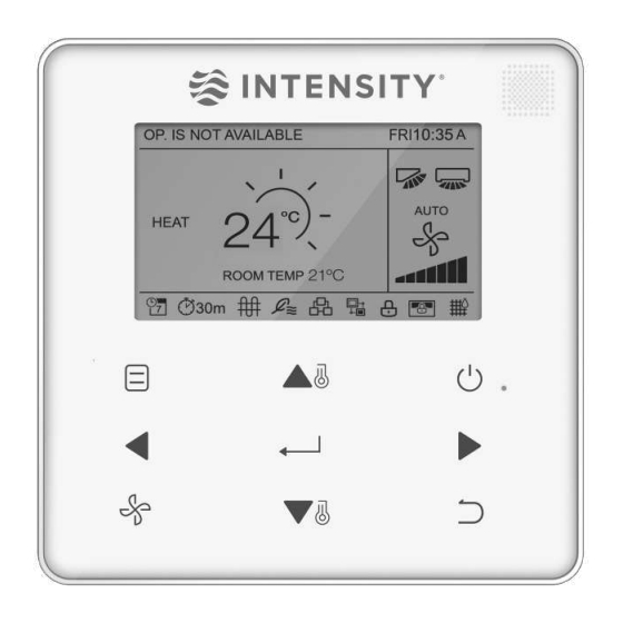
Page 47: Display Description
WDC-120G/WK(A) 1.2 Display Description Main Display Interface for Normal VRF indoor unit Fault Display Interface 202011... - Page 48 WDC-120G/WK(A) Description Implication Set Temperature Displays the set indoor temperature Mode Display Displays the running mode set by the wired controller Room Temperature Display Displays the current indoor temperature E-heat Icon Turns ON when indoor temperature Turns ON when the wired controller connects to the Fresh Fresh Air Processing Unit Icon Air Processing Unit.
- Page 49 WDC-120G/WK(A) Main Display Interface for HRV: Description Implication Set Temperature Displays the set indoor temperature Turns ON when the central controller/IMMPRO locks the IDU Central Controller / IMMPRO Locking Icon functions and the wired controller cannot use the corresponding functions of the IDU In heating mode the fan does not run when the indoor unit heat Cold Draft Prevention exchanger temperature is equal to or lower than the setting...
-
Page 50: Basic Operations
WDC-120G/WK(A) 2 Basic Operations 2.1 ON/OFF Press ON/OFF to turn the IDU ON/OFF. The LED is lit when the unit is turned ON as shown in the picture below: 202011... -
Page 51: Setting The Mode
WDC-120G/WK(A) 2.2 Setting the MODE Press MODE to set the mode of the IDU, as shown in the picture below: Important points: 1. When the wired controller is connected to the IDU through the CN2 port , it has the above 5 operating modes by default. -
Page 52: Setting The Fan Speed
WDC-120G/WK(A) 2.3 Setting the Fan Speed In COOL, Heat or Fan mode, press Fan to change the fan speed. When the IDU supports 7 fan speeds, press Fan to set the fan speed circulation as shown in the picture below. When the IDU supports 3 fan speeds, press FAN to set the fan speed circulation as shown in the picture below: 202011... -
Page 53: Setting The Temperature (For Normal Idus)
WDC-120G/WK(A) 2.4 Setting the Temperature (For normal IDUs) In the Auto, Cool, Dry or Heat mode, press TEMP UP or TEMP DOWN to adjust the temperature. In AUTO mode dual set point, adjust the set temperature for cooling when the COOL set temperature is highlighted as shown in the picture below: Press the Left or Right... -
Page 54: Key Lock
WDC-120G/WK(A) 2.5 Key lock Press the BACK button for 3 seconds while the backlight is illuminated. The icon is displayed. All the buttons are disabled. Use the button now and the icon will flicker 3 times to prompt. To cancel the key lock mode, hold BACK for 3 seconds while the backlight is already illuminated 202011... -
Page 55: Reset Filter Indicator
WDC-120G/WK(A) 2.6 Reset Filter Indicator When it is to clean or replace the filter, the filter indicator will be displayed. Hold the fan speed button and Left at the same time for 1 second to clear the icon display. Wash, clean or replace the filter or element. For details, refer to the manual provided together with the indoor unit For the HRV, if the pressure difference switch detects that the pressure difference is not proper, it means the filter needs to be cleaned/changed and then the pressure difference will be normal and then the clean filter icon will disappear. -
Page 56: Quick Reference Menu
WDC-120G/WK(A) 3 Quick Reference Menu Press the Menu/OK button to enter the Quick reference menu. Press TEMP UP and TEMP DOWN select and item. Press MENU/OK to enter. On the last level of the menu, press MENU/OK to confirm and return to the homepage. - Page 57 WDC-120G/WK(A) 8. Schedule: This function is used to create a weekly schedule which can be followed by the indoor units. 9. Date and Time: used to manage the date and time inside the controller. 10. Daylight Saving Time: Used to adjust the clock for daylight saving time. 11.
-
Page 58: Louver
WDC-120G/WK(A) 3.1 LOUVER The first Quick Reference Menu function available for the customer is LOUVER. For using the LOUVER function of the controller, the IDU must have an integrated LOUVER. MENU LOUVER AUX HEATER ECONOMY MODE SILENT MODE IDU LED INDICATIORS MENU/OK Choose LOUVER on the menu interface and press MENU/ OK , to enter the louver settings as shown in the picture... - Page 59 WDC-120G/WK(A) The figures below show the vertical and horizontal louver sequence respectively. (Default) Vertical louver adjustment sequence Horizontal louver adjustment sequence Horizontal louver will move the louvers from left to right ion a pre-determined fashion. This pattern is non-adjustable. 202011...
-
Page 60: Aux Heater
WDC-120G/WK(A) 3.2 AUX HEATER The second quick reference menu available for the customers is Auxiliary heater. When the IDU supports E-heat and the wired controller is ON, the AUX HEATER function can be set in the heating modes. Choose AUX HEATER on the menu interface as shown below and press MENU/OK to enter this setting. -
Page 61: Economy Mode (Except Hrv)
WDC-120G/WK(A) 3.3 ECONOMY MODE (Except HRV) The third option available in the quick reference menu is ECONOMY MODE. When the IDU supports the ECONOMY MODE and the wired controller is ON, the ECONOMY MODE can be set for operation in cooling and heating modes, Choose ECONOMY MODE on the menu interface as shown below and press MENU/OK to enter this setting. -
Page 62: Silent Mode
WDC-120G/WK(A) 3.4 SILENT MODE The fourth option on the Quick reference menu is Silent Mode. When the IDU supports the Silent Mode and the wired controller is ON, silent mode can be set for operation in cooling mode and heating mode. Choose Silent Mode on the menu interface as shown below and press MENU/OK to enter this setting Press TEMP UP... -
Page 63: Idu Led Indicators
WDC-120G/WK(A) 3.5 IDU LED INDICATORS The fifth setting on the Quick reference menu of the wired controller is IDU LED Indicators. When the IDU LED setting is enabled, the LED turns ON when the IDU starts. Choose IDU LED indicators on the menu interface as shown in the picture above and press MENU/OK to enter this setting. -
Page 64: Temperature Unit
WDC-120G/WK(A) 3.6 TEMPERATURE UNIT This is the sixth setting on the quick reference menu. Using this setting, we can set the temperature unit being displayed on the wired controller. Choose TEMPERATURE UNIT on the menu interface as shown below and press MENU/OK to enter this setting. -
Page 65: Timer
WDC-120G/WK(A) 3.7 TIMER The seventh function available on the quick reference menu of the controller is TIMER. Choose TIMER on the menu interface and press MENU/OK to enter this setting. Choose CONFIGURATION in the schedule level 1 menu and press MENU/OK to enter this setting. -
Page 66: Schedule
WDC-120G/WK(A) 3.8 SCHEDULE It is the eighth function on the quick reference menu. This function lets us to set a schedule for the various indoor units. Make sure that the clock is set before setting the schedule. Choose SCHEDULE on the menu interface and press MENU/OK to enter this setting. - Page 67 WDC-120G/WK(A) Choose daily pattern in this menu and press MENU/OK to open the menu. Press TEMP UP or TEMP DOWN to select the daily pattern as shown in the picture below. Button Description EVERYDAY Sets the schedule for each day from Monday to Sunday separately. Sets a schedule for Monday to Friday and a separately schedule for Saturday and Sunday Sets one schedule for Monday to Saturday and a separate schedule for...
- Page 68 WDC-120G/WK(A) Parameter Description WEEK Selects the specific day for timer settings TIME Sets the timer. Up to 8 time points can be set for each day Sets automatic ON/OFF and the running mode Sets the fan speed COOL When AUTO or COOL mode is set, sets the cooling temperature value HEAT When AUTO or HEAT mode is set, sets the heating temperature value After setting the schedule, press MENU/OK...
- Page 69 WDC-120G/WK(A) 4. EXTENSION The EXTENSION function can only be set when the weekly schedule is enabled. The EXTENSION function will set the amount of time by which the settings can be extended before returning to the predetermined schedule pattern. Choose EXTENSION in the schedule menu and press MENU/OK to enter this setting.
-
Page 70: Date And Time
WDC-120G/WK(A) 3.9 DATE AND TIME This is the ninth function on the Quick reference menu. Choose Date and Time on the menu interface and press MENU/OK to enter this setting. Press the LEFT or RIGHT button to move the cursor and press TEMP UP or TEMP DOWN to set the date as shown in the picture below. - Page 71 WDC-120G/WK(A) Open 24-HOUR FORMAT and press TEMP UP or TEMP DOWN to select the time format, as shown in the picture below. When it is disabled, the controller will use the 12-hour format. 202011...
- Page 72 WDC-120G/WK(A) 202011...
-
Page 73: Daylight Saving Time
WDC-120G/WK(A) 3.10 DAYLIGHT SAVING TIME This is the tenth function on the quick reference menu. When enabled, the clock automatically moves forward by an hour at 2 a.m. on the specified start date and it goes back by an hour at 2 a.m. on the specified end date. Choose DAYLIGHT SAVING TIME on the menu interface and press MENU/OK to enter this setting as shown below: ENABLE/DISABLE: Press TEMP UP... - Page 74 WDC-120G/WK(A) END: Use the cursor to choose END and press MENU/OK to enter this setting. Press the LEFT or RIGHT button to move the cursor and TEMP UP or TEMP DOWN button to set the end time for daylight saving time as shown in the picture below: 202011...
-
Page 75: Room Temperatutre (Except Hrv)
WDC-120G/WK(A) 3.11 ROOM TEMPERATUTRE (Except HRV) When the room temperature display is set, the current room temperature will be displayed on the homepage as shown in the picture below: Choose ROOM TEMPERATURE on the menu interface as shown in the picture below and press MENU/OK to enter this setting. -
Page 76: Wired Controller Lock
WDC-120G/WK(A) 3.12 WIRED CONTROLLER LOCK The wired controller can lock the following functions on the IDU and as a result they cannot be adjusted by the user from the remote controller. 1. Switch ON/OFF function 2. Running Mode 3. Temperature Setting 4. -
Page 77: Keypress Tone
WDC-120G/WK(A) 3.13 KEYPRESS TONE This is the thirteenth function on the quick reference menu. Choose KEYPRESS TONE on the menu interface as shown in the picture below to enter this setting. Press TEMP UP or TEMP DOWN to set the KEYPRESS TONE ENABLED or DISABLED as shown in the picture below: 202011... -
Page 78: Idu Led Indicators (Except Hrv)
WDC-120G/WK(A) 3.14 IDU LED INDICATORS (Except HRV) This is the last function on the quick reference menu. When the IDU LED setting is enabled, the LED turns ON when the IDU starts. Choose IDU LED INDICATORS on the menu interface as shown in the picture below and press MENU/OK to enter this setting. -
Page 79: Outdoor Temperature Display (For Hrv Only)
WDC-120G/WK(A) 3.15 Outdoor Temperature Display (For HRV Only) When the outdoor temperature display is set, the current outdoor temperature will be displayed on the homepage as is shown in the figure below: Choose OUTDOOR TEMPERATURE on the menu interface as shown in the figure below and press MENU/OK to enter this setting. -
Page 80: Sterilization Function
WDC-120G/WK(A) Enter the Interlock menu as is shown in the figure below: MENU KEYPRESS TONE INTERLOCK OFF TIMER DRY CONTACT LANGUAGE MENU/OK Press TEMP UP and TEMP DOWN to set the INTERLOCK ENABLED or DISABLED as shown in the figure below: MENU - DRY CONTACT 1-FAN ENABLED MENU/OK... -
Page 81: Setting The Language
WDC-120G/WK(A) Press TEMP UP and TEMP DOWN to select the STERILIZATION ENABLED or DISABLED as shown in the figure below: MENU - STERILIZATION ENABLED MENU/OK Setting the Sterilization Function Display 3.18 Setting the Language Enter the Language setting Menu to choose the language as is shown in the figure below: MENU KEYPRESS TONE LED INDICATOR... -
Page 82: Setting The Off Timer
WDC-120G/WK(A) 3.19 Setting the Off Timer Enter the Off Timer Setting Menu, as is shown in the figure below: MENU KEYPRESS TONE LED INDICATOR OFF TIMER STERILIZATION LANGUAGE MENU/OK Accessing the Off Timer setting menu Press TEMP UP and TEMP DOWN to select the Off... -
Page 83: Setting The Dry Contact (Hrv & Fresh Air Processing Units Only)
WDC-120G/WK(A) 3.20 Setting the Dry Contact (HRV) Enter the Dry Contact Menu as shown in the figure below: MENU KEYPRESS TONE LED INDIC ATOR OFF TIMER DRY CONTACT LANGUAGE MENU/OK Press TEMP UP and TEMP DOWN to select the Dry Contact 1-3 as shown in the figure below: MENU-DRY CONTACT DRY CONTACT 1-FAN DRY CONTACT 2 - CTON... - Page 84 WDC-120G/WK(A) 202011...
- Page 85 WDC-120G/WK(A) Part 4 Troubleshooting 1 TROUBLESHOOTING ........................... 82 1.1 No Display on the Wired Controller ....................82 1.2 E9: Wired Controller and IDU communication fault ..............83 1.3 F7: Wired controller EEPROM fault ....................84 1.4 For any “Group” the number of IDUs is not consistent with the actual number of connected IDUs 85 2 FREQUENTLY ASKED QUESTIONS ......................
- Page 86 WDC-120G/WK(A) 1 TROUBLESHOOTING In this section, we will try to provide some basic troubleshooting for the controller. 1.1 No Display on the Wired Controller CASE 1 REASON: IDU is not powered ON SOLUTION: Turn ON the IDU CASE 2 REASON: Wired Controller connection error. SOLUTION: First power OFF the IDU and check if the wired controller connection is correct or not.
- Page 87 WDC-120G/WK(A) 1.2 E9: Wired Controller and IDU communication fault CASE 1 REASON: No address set for IDU or IDU address is duplicated. SOLUTION: Set an address for the IDU ; duplicated addresses are not allowed. CASE 2 REASON: Main/Secondary controller is not set when two wired controllers control one or multiple IDUs SOLUTION: Set one wired controller to secondary wired controller.
- Page 88 WDC-120G/WK(A) 1.3 F7: Wired controller EEPROM fault CASE 1 REASON: EEPROM data error SOLUTION: Press “MODE” + “MENU” + “TEMP UP” + “TEMP DOWN” for more than 3 seconds to reset the wired controller until the default status appears CASE 2 REASON: Wired controller damaged.
- Page 89 WDC-120G/WK(A) 1.4 For any “Group” the number of IDUs is not consistent with the actual number of connected IDUs CASE 1 REASON: D1/D2 communication wiring error or bad contact in individual IDU. IDU addresses have not been set or duplicate addresses. SOLUTION: Check and adjust the D1/D2 communication line.
- Page 90 WDC-120G/WK(A) 2 Frequently Asked Questions In this section, we have tried to answer some of the frequently asked questions that may come to the mind of the user or the installer while using the WDC-120G/WK connected with indoor unit scenario. FAQ 1 Group Control Under the group control, the following points need to be taken into attention: 1.
- Page 91 WDC-120G/WK(A) Part 5 Appendix 1 APPENDIX 1 ............................88 2 APPENDIX 2 ............................89 202011...
- Page 92 WDC-120G/WK(A) 1 Appendix 1 In this section, we have given the details about the outdoor unit information which is available to be checked by the Field Settings menu of the wired controller Information Unit Address Outdoor ambient (T4) temperature °C T2/T2B average temperature °C Main Heat Exchanger pipe temperature (T3) °C Discharge temperature of compressor A °C...
- Page 93 WDC-120G/WK(A) 2 Appendix 2 In this section, we have provided the details about the indoor unit information which is available to be checked by the Field settings menu of the wired controller. The information which are on offer are as follows: Information IDU Communication Address Capacity (HP) of IDU...
- Page 94 WDC-120G/WK(A) 202011...
Need help?
Do you have a question about the WDC-120G/WK(A) and is the answer not in the manual?
Questions and answers