
Related Manuals for Left Hand Robotics RT-1000


Summary of Contents for Left Hand Robotics RT-1000
- Page 1 INSTALLATION GUIDE: USER GUIDE: BASE STATION RT-1000 Version 2017.12.14 Version 2020.01.21...
-
Page 2: Copyright
Copyright © 2020, Left Hand Robotics, Inc. All Rights Reserved Left Hand Robotics, Inc. 1880 Industrial Circle Suite E Longmont, CO 80503... -
Page 3: Table Of Contents
Table of Contents Copyright Table of Contents Before Starting the Robot Safety Instructions Driving the Robot Starting the Robot Drive Mode Xbox Controller Diagram Xbox and Robot Calibration Autonomous Mode Xbox Controller Record on Robot LHR Mobile App Drive to Start Faults Automatic Faults Manual Faults... -
Page 4: Before Starting The Robot
• Set up your user account after receiving the invitation to the ROC website. (https://roc.lefthandrobotics.com). • Download the Left Hand Robotics App (the mobile version of the ROC) on your iOS or Android device. • Login into the LHR App with your ROC account credentials. -
Page 5: Safety Instructions
Paths. Safety Instructions The RT-1000 was designed to offer repetitive safe service when operated and maintained properly. Although hazard control and accident prevention are partially dependent upon the design and configuration of the vehicle, these factors are also dependent upon the awareness, concern and proper training of the personnel involved in the operation, transport, maintenance and storage of the machine. -
Page 6: Driving The Robot
• Do not touch engine, exhaust system components, pumps, alternator or radiator while engine is running or soon after it is stopped. These areas could be hot enough to cause burns. • Before leaving the vehicle: o Stop movement of the vehicle. o Lower Attachment. -
Page 7: Xbox Controller Diagram
RT-1000 Xbox Controller Diagram Quick Descriptions Xbox Logo – Turns the Xbox controller on, light may continue to blink even once on and connected. This is to be expected. Speed – Push up to move the Robot forward. Push downward to move the Robot in reverse. The Robot does not coast. -
Page 8: Xbox And Robot Calibration
Run - Once a Path, Field or Playlist is pre-loaded on the Robot, (A) will actively Run the autonomous program. Hit the (A) button again to take the Robot out of an autonomous program and to stop the Robot. Quick Descriptions RT –... -
Page 9: Autonomous Mode
• Before running an autonomous program, a Job Site and a pre-recorded, edited and downloaded Path or Field must be set up on the ROC. • The Left Hand Robotics App must be downloaded on to the User’s Smart Device. LHR does not support the ROC in website form via a Browser. -
Page 10: Record On Robot
Drive to Start is an advanced manual feature that allows the user to effectively position the Robot at the start of a Loaded Path. The RT-1000 will calculate the most direct route to the start of the Loaded Path or Field regardless of what obstacles are in its way. There is no obstacle detection during this special Drive mode. -
Page 11: Automatic Faults
Fault Types There are two kinds of Faults. Automatic Faults are Faults that, for the most part, the Robot can recover from on its own. Manual Faults require intervention from the User before the Robot can resume an Autonomous program. The following is a list of the most common Faults. Automatic Faults OBSTACLE –... -
Page 12: Rescue Tether
Rescue Tether The RT-1000 Robot is delivered with a Rescue Tether accessory capable of powering and moving the Robot in scenarios where the main electronics board is not functional. Use of the Rescue Tether is ONLY recommended in situations where the machine has ceased operation in a dangerous situation or where it may have become disabled and poses a hazard or disruption to regular pedestrian or vehicular traffic. - Page 13 Robot Connections The Rescue Tether uses three of the Robot cables harnesses that are connected to the electronics box inside the right service panel (Figure 2 and Figure 3). Power, Valve 1 and Valve 2 connections should be removed from the electronics box and plugged into the Rescue Tether cables (Figure 4 and Figure 5).
- Page 14 Figure 2 – Robot Service Panel Figure 3 – Robot Electronics Control Box Figure 4 - Power / Valve 1 / Valve 2 Figure 5- Power / Valve 1 / Valve 2 Cables Disconnected From Elec. Box Cables Connected To Rescue Harness Cables...
- Page 15 Figure 6 - Power / Valve 1 / Valve 2 Figure 7 - Rescue Tether Harness Cables Are Connected Properly Cable Harness attached to (Connectors are Labelled) Rescue Tether Box. (Connector 1 and 2) Rescue Tether Operation Robot Power - Once all the Rescue Tether connections are made, switch the power toggle on, which is located near the battery to the rear of the Robot.
-
Page 16: Attachments
Driving Forward and Reverse - Once the engine is started, the Robot can be driven freely. Prior to pressing the drive lever, the Speed Control Dial (see Figure 1) should be turned fully counterclockwise. This will ensure the speed is at the absolute minimum. When ready to drive, hold the lever in forward or reverse and slowly turn the speed dial clockwise to start the robot moving. - Page 17 Attaching the Broom Attaching the Broom is best done with two people. One driving the Robot, and one managing the attachment itself. When storing the Broom, when not attached to the Robot, tilt the Broom itself so that the hitch is on the ground, but the bristles are not. Pivot Sensors Pivot Accessory...
-
Page 18: Broom
Pivot Sensors Pivot Broom Hoses Hoses • Pivot the Broom Attachment channel upwards. • Drive the Robot slowly forward to insert the Lift Plate into the Channel. • Place cotter pin into the back of the Channel. NOTE: only one cotter pin is included, and the same pin is used between Broom and Mower Attachments. -
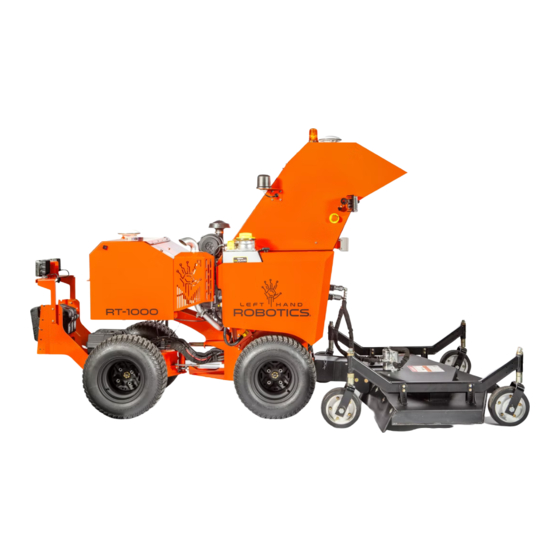
Page 19: Mower Deck
Attach Mower Deck Mower Deck Hoses • Turn engine on. • Drive the Robot slowly forward to insert the Lift Plate into the Channel. • Place cotter pin into the back of the Channel. NOTE: only one cotter pin is included, and the same pin is used between Broom and Mower Deck. -
Page 20: Broom Safety Bar Spring Reinforcement
Broom Safety Bar Spring Reinforcement “False positive” Broom Safety Bar faults occasionally happen when the Broom Attachment bounces on rough terrain and it falsely triggers the bar. To prevent this, we recommend the following corrective actions: • Adjust the gap between the 2 safety bar proximity switches and the metal sweeper to be near zero. -
Page 21: Service And Maintenance
Service and Scheduled Maintenance The RT-1000 will need to have service and regularly scheduled maintenance. For a complete list of these, please see the RT-1000 Service Manual.
Need help?
Do you have a question about the RT-1000 and is the answer not in the manual?
Questions and answers