Table of Contents

Related Manuals for ISYGLT UD-700-X2

Summary of Contents for ISYGLT UD-700-X2
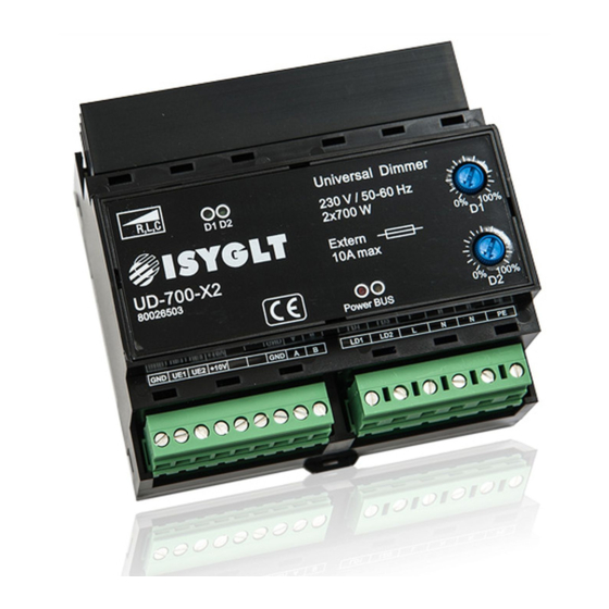
- Page 1 Technical Data / Instruction Manual UD-700-X2 Article no. 80026503 Universal Dimmer Seebacher GmbH www.seebacher.de Phone: +49 (0) 80 41 / 77 77 6 Marktstrasse 57, 83646 Bad Tölz info@seebacher.de Fax: +49 (0) 80 41 / 77 77 2...
-
Page 2: Notes On Documentation
These instructions are intended for qualified personnel who are 1. Notes on documentation familiar with the assembly, installation and operation of the ISYGLT system. It is essential that you read these operating instructions through before commissioning and keep them accessible for further 1.1. -
Page 3: Safety Instructions
Protect module from humidity • and configuration of the ISYGLT module may only be carried out by trained staff. In addition to these safety instructions, you must also observe the special safety instructions listed in the individual chapters for Observe the electrical installation regulations of the country in which the individual acts. -
Page 4: Warranty
These are limited to the intended use of the module and refer EU on waste electrical and electronic equipment at the local collec- to the repair or replacement of the ISYGLT module. Please send the tion points for waste electrical and electronic equipment! device with an attached error description to our company address given below. -
Page 5: Product Description
- is thus possible without any additional measu- tion of 16 bit and thus meets the highest demands. The properties ring equipment. All you need is the connected UD-700-X2 dimmer, already predefined in the factory, such as dimming curves, minimum a USB cable (USB Type A to Micro B m/m) and our free software. - Page 6 1Hz blinking Too high mains voltage (>400Vs) 1x blinking + break 1.5s Error in self-test After the ISYGLT dialing (DIP switches) no valid ISYGLT version is recognized 2x blinking + break 1.5s 3x blinking + break 1.5s No valid parameters available...
- Page 7 DIP switches DMX-512 operating mode Sample DMX start address 331 Address bit Mode 1 2 3 4 5 6 7 8 1 2 3 4 5 6 7 8 Address 0 to 511 DIP switches stand-alone operating mode Mode 1 2 3 4 5 6 7 8 1 2 3 4 5 6 7 8 Dimming channel 1 Dimming channel 2...
-
Page 8: Technical Data
DIP C DIP D Setting dimming characteristics such as min-max values, curves, etc. (see PC program for UD-700-X2) Parameters of the 1st column („General“ in the PC program UD-700-X2) Parameters of the 2nd column („General“ in the PC program UD-700-X2) Parameters of the 3rd column („General“... - Page 9 Control voltage input for dimmer output LD2 (emergency function) +10V Power supply for external potentiometer(s) Reserve Reserve Reference potential (Ground) for the voltage inputs (0-10V) and BUS RS-485 ISYGLT subnet BUS RS-485 ISYGLT subnet BUS RS-485 6-pole plug (right) Terminal Internal connections Meaning Dimmer 1 load output 0...230V max.
- Page 10 Sample views of PC program Oscillogram of retrofit LEDs in trailing edge mode Custom dim curves Tab „General“ Tab „Special functions“ Seebacher GmbH www.seebacher.de Phone: +49 (0) 80 41 / 77 77 6 Marktstrasse 57, 83646 Bad Tölz info@seebacher.de Fax: +49 (0) 80 41 / 77 77 2...
-
Page 11: Wiring Diagram
11. Wiring diagram Sample: controlled by ISYGLT 2x700W +24V BUS-A BUS-B 1 2 3 4 5 6 7 8 1 2 3 4 5 6 7 8 e.g. ISYGLT-Adr.5 ISYGLT UD-700-X2 Art.-Nr.: 80026503 max. 2x700VA optional: external voltage control e.g. emergency function... - Page 12 Sample: controlled by ISYGLT 1x1400W +24V BUS-A BUS-B 1 2 3 4 5 6 7 8 1 2 3 4 5 6 7 8 e.g. ISYGLT-Adr.5 ISYGLT UD-700-X2 Art.-Nr.: 80026503 max. 2x700VA optional: external voltage control e.g. emergency function 0(1)-10V channel 1 max.
- Page 13 1 2 3 4 5 6 7 8 1 2 3 4 5 6 7 8 e.g. 8 Bit DMX start adr.261 for more DIP switch options please use the datasheet ISYGLT UD-700-X2 Art.-Nr.: 80026503 max. 2x700VA optional: external voltage control e.g.
- Page 14 Sample: 1-10V and 1-button dimming 1 2 3 4 5 6 7 8 1 2 3 4 5 6 7 8 DIP switches please use the datasheet ISYGLT UD-700-X2 Art.-Nr.: 80026503 max. 2x700VA max. 700W max. 700W trailing or trailing or...
- Page 15 Sample: Potentiometer 10kOhm 1 2 3 4 5 6 7 8 1 2 3 4 5 6 7 8 DIP switches please use the datasheet ISYGLT UD-700-X2 Art.-Nr.: 80026503 max. 2x700VA max. 700W max. 700W trailing or trailing or leading edge...
Need help?
Do you have a question about the UD-700-X2 and is the answer not in the manual?
Questions and answers