Table of Contents
Advertisement
Air Fuel Ratio Control System
with open / closed Control Loop
Copyright 2007 by Heinzmann GmbH & Co. KG All rights reserved. This publication may not be reproduced by any means whatsoever or
passed on to any third parties.
HEINZMANN
Engine & Turbine Controls
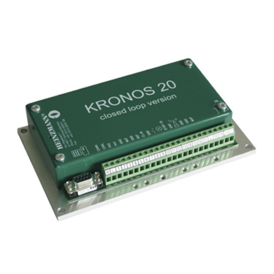
KRONOS 20
Electronically controlled
for Gas Engines
Heinzmann GmbH & Co. KG
Engine & Turbine Controls
Am Haselbach 1
D-79677 Schönau (Schwarzwald)
Germany
Phone
+49 7673 8208-0
Fax
+49 7673 8208-188
Email
info@heinzmann.com
www.heinzmann.com
V.A.T. No: DE145551926
®
Manual AFR 03 002-e / 01-08
Advertisement
Table of Contents

Related Manuals for Heinzmann KRONOS 20


Summary of Contents for Heinzmann KRONOS 20
- Page 1 Gas Engines with open / closed Control Loop Copyright 2007 by Heinzmann GmbH & Co. KG All rights reserved. This publication may not be reproduced by any means whatsoever or passed on to any third parties. Manual AFR 03 002-e / 01-08...
- Page 3 Practice all plant and safety instructions and precautions. Warning Failure to follow instructions may result in personal injury and/or dam- age to property. HEINZMANN will refuse all liability for injury or damage which re- sults from not following instructions Danger Please note before commissioning the installation:...
- Page 4 HEINZMANN expressly disclaim the implied warranties of merchant- ability and of fitness for any particular purpose, even if HEINZMANN have been advised of a particular purpose and even if a particular pur- pose is indicated in the manual.
-
Page 5: Table Of Contents
3.4 λ Sensor LSM 11 for Exhaust Gas Measurement (optional)......... 15 3.4.1 Technical Data ....................... 15 3.4.2 Dimensional Drawing .................... 17 4 Control Unit KRONOS 20....................18 4.1 Technical Data....................... 18 4.1.1 General........................18 4.1.2 Inputs and Outputs ....................19... - Page 6 6.1.2 Wiring Diagram for KRONOS 20 with closed Loop (power signal, CH signal)..........................33 6.1.3 Wiring Diagram for KRONOS 20 with λ-Sensor Signal ........34 6.2 Cable Harness........................ 35 6.3 Enclosed Cables......................36 6.3.1 Cable W2 to Gas Valve E-LES................36 6.3.2 Cable W3 to Pressure / Temperature Sensor P/T-S-01..........
- Page 7 14.4 List 3: Functions ......................89 14.5 List 4: Characteristics and Maps ................. 92 15 Figure List.......................... 94 16 EC Declaration of Conformity ..................95 17 Order Form for KRONOS Systems ................96 18 Order Specifications for Manuals..................97 KRONOS 20...
-
Page 9: Safety Instructions And Related Symbols
If, however, some safety instruction is preceded by the warning triangle labelled “Caution” this will indicate that danger of life or personal injury is not involved. The symbols used in the text do not supersede the safety instructions. So please do not skip the respective texts but read them thoroughly! KRONOS 20... -
Page 10: Basic Safety Measures For Normal Operation
• Refasten loose connections! • Replace at once any damaged lines and/or cables! • Keep the cabinet always closed. Access should be permitted only to authorized per- sons having a key or tools. KRONOS 20... -
Page 11: Before Putting An Installation Into Service After Maintenance And Repair Works
Check on all slackened screw connections to have been tightened again! • Make sure the control linkage has been reattached and all cables have been recon- nected. • Make sure all safety devices of the installation are in perfect order and are working properly! KRONOS 20... -
Page 12: General
• Easy adaptation to different engine and gas types, requiring only minor parameter modifications • Only three sensors are required accordingly simple installation and reliable operation • Simple and easy parameter setting and diagnosis with HEINZMANN DcDesk 2000 communications software Optional:... -
Page 13: System Components
• Optional λ sensor • Optional gas mixer from KRONOS 10 This system components may only be combined with gas mixers that meet the HEINZMANN specifications. If a different gas mixer shall be used con- Note sult HEINZMANN. 2.4 System Specifications All ATEX certified components are suitable for zone 2. -
Page 14: Operational Principle
The volume flow rate of the E-LES gas valve depends on the gas mixer and its design. The indicated performance range is valid only if the gas valve design is done by HEINZMANN. For applications combined with other gas mixers the volume flow rate can be 50% lower. -
Page 15: General Application
A digitally controlled MAS like the HEINZMANN E-LES (digital lambda adjustment screw) that receives its inputs from a speed and load dependent map and reacts to gas pres- sure and mixture temperature variations, makes it possible to obtain an ideal gas-air mix- ture under all operating conditions. -
Page 16: Additional Functions
In an ex- tended closed-loop version it allows compensation for changes in gas quality and envi- ronmental factors. This makes it possible to use biogas with minimal emissions. Figure 1: KRONOS 20 System 2.7 Additional Functions • Engine Stop On activation of the digital input for engine stop, the gas valve will be completely closed in dependence of the parameter settings until the engine stops. -
Page 17: Gas Train
HEINZMANN recommends to attach the governor not to the engine but to the frame. The pressure governor is not included in the standard scope of delivery of the KRONOS 20 system. On request, it can be delivered by HEINZMANN or a specific pressure regulator can be recommended by HEINZMANN. -
Page 18: Sensors
Temperature range housing -8°C to +120°C cable -5°C to +80°C Protection grade IP 55 Vibration < 10g, 10 to 100 Hz Shock < 50g, 11 ms half sine Connector used SV 6 - IA - 2K (EDV-No: 010-02-170-00) KRONOS 20... -
Page 19: Mounting Position
The mounting position of the speed pickup must be such as to allow a frequency as high as possible. The HEINZMANN digital control of the KRONOS 20 series is normally designed for a frequency of max. 9,000 Hz. Frequency may be calculated as follows:... -
Page 20: Dimensional Drawing
02 - 76 M 16 x 1.5 connector 03 - 102 M 16 x 1.5 used 11 - 38 5/8"-18UNF-2A SV6-IA-2K 12 - 76 5/8"-18UNF-2A (010-02-170-00) 13 - 102 5/8"-18UNF-2A The according name for ordering is e.g., IA 02-76. KRONOS 20... -
Page 21: Atex Certification Of Speed Pickups
EN 50021:1999 flame proof protection type "n". If the speed pickups are used in such an ambient and require an ATEX certificate, the wiring of the pickup must be done and delivered by HEINZMANN too. In this case, HEINZMANN will attach the following information sign to the wire close to the speed pickup plug: HEINZMANN GmbH &... -
Page 22: Dimensional Drawing
Mounting screw thread 3.3.3 Mounting The sensor is designed for mounting on an even surface of the intake manifold. The pressure joint and the temperature sensor reach into the manifold together and are sealed against atmosphere with an O-ring. KRONOS 20... -
Page 23: Atex Certification For Double Sensor P/T-S-01
EN 60 079-15:2003 (type of protection "n"). If the sensor is used in such an ambient and require an ATEX certificate, the wiring of the sensor must be done by HEINZMANN too. In this case, HEINZMANN will attach the following sticker to the wire close to the sensor plug: HEINZMANN GmbH &... - Page 24 In unfavourable conditions, ground circuit loops may hap- pen that falsify the output signal considerably and thus disturb con- Warning trol activity. This must be taken into account during commissioning. It may be necessary to optimize the wiring or to use a galvanic sepa- ration. KRONOS 20...
-
Page 25: Dimensional Drawing
3 Sensors 3.4.2 Dimensional Drawing 22,6 M18x1,5 SW 22 21,8 Figure 7: Dimensional Drawing λ Sensor LSM 11 KRONOS 20... -
Page 26: Control Unit Kronos 20
4 Control Unit KRONOS 20 4 Control Unit KRONOS 20 4.1 Technical Data 4.1.1 General Power supply 12 V DC or 24 V DC Min. voltage 10 V DC Max. voltage 32 V DC Residual ripple max. 10 % maximum at 100 Hz Current consumption max. -
Page 27: Inputs And Outputs
4 Control Unit KRONOS 20 4.1.2 Inputs and Outputs All inputs and outputs are reverse polarity protected and short-circuit-proof against bat- tery plus and minus. Temperature input (terminal 4) for PT1000 / Ni1000 sensors Tolerances: < ±2°C at 0°C to 130°C, otherwise <... -
Page 28: Dimensional Drawing
4 Control Unit KRONOS 20 4.2 Dimensional Drawing 118,5 84,5 Figure 8: Dimensional Drawing of Control Unit KRONOS 20 with Power Signal Input The fastening element for top-hat-rail in the above drawing is available on re- quest. Note KRONOS 20... - Page 29 4 Control Unit KRONOS 20 118,5 84,5 Figure 9: Dimensional drawing of control unit KRONOS 20 with λ sensor input The fastening element for top-hat rail in the above drawing is available on re- quest. Note KRONOS 20...
-
Page 30: Mounting Position
4 Control Unit KRONOS 20 4.3 Mounting Position When the mounting position is chosen, attention should be paid to easy accessibility of the connection terminals and to the possibility of having to substitute the unit on site. Mount- ing position is optional. When the unit is mounted directly on the engine, it must be fas- tened to vibration dampeners. -
Page 31: Gas Valves E-Les
The control electronics of the stepping motor is mounted directly onto the gas valve and is controlled by the KRONOS control unit with a special bit pattern via 2 digital outputs. This type of control in principle allows the use of different HEINZMANN control units for dif- ferent purposes. -
Page 32: Technical Data
9 g at 64..2000 Hz Shock 50 g, 11 ms, half sine Protection grade IP 55 89/336/EEC and 95/54/EEC Connection DIN 45321; 7 pin male Gas valves E-LES might only be used as control valves! Never use as shut-off valve! Warning KRONOS 20... -
Page 33: Additional Specifications For Gas Valve E-Les 30
Positioning time for 0..100% 4 seconds Weight approx. 1.8 kg 5.2.4 Additional Specifications for Gas Valve E-LES 80 Min. voltage 18 V DC Valve resolution 3800 steps at 19 revolutions Positioning time for 0..100% 8 seconds Weight approx. 12 kg KRONOS 20... -
Page 34: Dimensional Drawings
DO NOT DISCONNECT WHILE CIRCUIT IS LIVE UNLESS AREA IS KNOWN TO BE NON-HAZARDOUS! BEFORE REMOVING THE COVER, SWITCH OFF THE POWER SUPPLY AND WAIT AT MINIMUM 5 SECONDS TO DISCHARGE THE ENERGY OF THE CAPACITIES! Figure 10: Dimensional Drawing E-LES 30 KRONOS 20... - Page 35 5 Gas Valves E-LES DIN 2999-R2 58,5 62,5 48,5 Figure 11: Dimensional Drawing E-LES 50 KRONOS 20...
- Page 36 5 Gas Valves E-LES Connection flange fitting to welding-neck flange according to DIN 2633 PN 16 DN 80 Figure 12: Dimensional Drawing E-LES 80 KRONOS 20...
-
Page 37: Mounting
If the gas valves are used in such a context and require an ATEX certificate, the wiring of the gas valve must be done and delivered by HEINZMANN too. The inside of the gas-containing parts has not been taken into account for the ATEX valuation. - Page 38 5 Gas Valves E-LES Sign 1 shows the general and ATEX-relevant information. HEINZMANN GmbH & Co. KG Germany Tel.: +49 7673 8208-0 www.heinzmann.com II3G EEx nA II T4 : -20°C to +80°C TÜV 07 ATEX xxxxxx Figure 13: Sign bearing general and ATEX-relevant Information Sign 2 bears the exact type designation and serial number.
-
Page 39: Electric Connection
The electric connection must be done in accordance with the wiring diagrams provided by HEINZMANN and by the plant builder. Only specified cable types may be used for wiring. All indicated cable cross-sections must be adhered to at all costs. -
Page 40: Wiring Diagrams
12/24 V T x D Battery Connection to Electronically Programmer controlled MAS or PC Temperature Sensor E-LES Boost Pressure Sensor Common Alarm Engine Stop Magnetic Pickup IA .. Figure 16: Wiring Diagram for KRONOS 20 with open Loop KRONOS 20... -
Page 41: Signal)
Battery Connection to Electronically Programmer controlled MAS or PC Temperature Sensor E-LES Boost Pressure Sensor Load Signal or CH -Signal Common Alarm Engine Stop Magnetic Pickup IA .. Figure 17: Wiring Diagram for KRONOS 20 with closed Loop KRONOS 20... -
Page 42: Wiring Diagram For Kronos 20 With Λ-Sensor Signal
PC Temperature Sensor E-LES Boost Pressure Sensor grey - Lambda-Signal black + white Heater for Lambda-Sensor white Summenalarm Engine Stop Magnetic Pickup IA .. Figure 18: Wiring Diagram for KRONOS 20 with closed Loop and λ-Sensor Signal KRONOS 20... -
Page 43: Cable Harness
6 Electric Connection 6.2 Cable Harness Control Unit KRONOS 20 Battery Closed Loop Input E-LES Digital Inputs Temperature- / Pressure Sensor Error Indicators Magnetic Pickup Communication Figure 19: Cable designations power supply max. length 15 m 2 x 1.50 mm²... -
Page 44: Enclosed Cables
6 Electric Connection 6.3 Enclosed Cables The following cables will be provided by HEINZMANN in the required length. 6.3.1 Cable W2 to Gas Valve E-LES Terminal Assignment of Cable Terminal Plug Pin Function Colour Ground brown green Phase 2 yellow... -
Page 45: Cable W3 To Pressure / Temperature Sensor P/T-S-01
6 Electric Connection 6.3.2 Cable W3 to Pressure / Temperature Sensor P/T-S-01 Terminal Assignment of Cable Terminal Plug Pin Function Colour Ground brown NTC Signal white + 5V green Pressure Signal yellow Housing Screen Figure 21: Cable W3 KRONOS 20... -
Page 46: Cable W4 To Speed Pickup Ia
6 Electric Connection 6.3.3 Cable W4 to Speed Pickup IA… Terminal Assignment of Cable Terminal Plug Pin Function Ground Signal Housing Screen Figure 22: Cable W4 KRONOS 20... -
Page 47: Cable W5 To Λ-Sensor Lsm 11
6 Electric Connection 6.3.4 Cable W5 to λ-Sensor LSM 11 green yellow white brown Terminal Assignment of Cable Terminal Function Colour Sensor + yellow Sensor - green Heater white Heater black Figure 23: Cable W5 for λ-Control KRONOS 20... -
Page 48: Parameter Settings For Control Unit Kronos 20
(communications tool) are available. Only a few basic parameters are pre-set in the HEINZMANN factory. This means that the digital governor usually gets its definitive set of data from a source external to HEINZMANN. -
Page 49: General Mounting Instructions
All components must be installed only in the allowed areas. All components must be installed in a way to protect their connectors from impact damage. The inside of the components (gas containing parts) is not part of the ATEX speci- fication. Note KRONOS 20... -
Page 50: Commissioning
Ensure adequate overspeed protection! Danger • Start the engine after pre-setting according to the description below. • Optimization of lambda map and correction values as described below. Knock protection must be active or attention must be paid to audible knocking. Warning KRONOS 20... -
Page 51: Commissioning For Open Loop (Open Control Circuit)
Pressure offset should not normally be higher than + 2..3 mbar to ensure a safe engine start. Experience shows that this is where errors frequently happen. After engine warm-up the AFR control must be verified in open loop (5400 ClosedOrO- penLoop=0 ) and with different load-points according to the following procedure: KRONOS 20... - Page 52 This relation is based on the gas data and the desired lambda. The calibration is started with rated power and repeated at three other load points. It is advisable to calibrate the map. KRONOS 20...
-
Page 53: Further Commissioning For Closed Loop (Closed Control Circuit) With Output Power
λ value. The parameter values pre-set by HEINZMANN usually lead to a satisfactory control result both for open loop and for closed loop and constitute a good starting point for fine tuning. - Page 54 Observe that the speed of the AFR control is approx. 25 times slower than the speed of the speed control circuit. 2. Switch on Closed Loop Mode (5400 ClosedOrOpenLoop = 1). 3. Mark the position of the adjustment spindle of the zero governor. KRONOS 20...
-
Page 55: Further Commissioning For Closed Loop With Λ1 Control (Kronos 20 Version With Λ1 Sensor)
(control reserve) and the control system (correction quality). 9.5 Further commissioning for CLOSED LOOP with λ1 control (KRONOS 20 version with λ1 sensor) General: Commissioning of λ 1 control is carried out in two steps:... - Page 56 (1464 LambdaTrimValueLimit ) must be set to a correspondingly high value. On the other hand, it should guaranteed that in case of sensor failure the engine still runs within a safe range. 5. To conclude, check the open loop settings once more. KRONOS 20...
-
Page 57: Misfire Detection (Optional)
10 Misfire Detection (optional) 10.1 General Misfire detection is available as an optional function in KRONOS 20. It is based on the ob- servation of the speed variation caused by each ignition. Since only speed and power sig- nals are used, no additional sensor is required. - Page 58 ) falls below the load-dependent trigger level by relative 15 % the error (3046 ErrMisfireWarns ) is cleared. The emergency shutoff signal (3047 ErrMisfireEcy ) on the other hand can be cleared only by a reset or by an error clearing through a commu- nication module or switch function. KRONOS 20...
-
Page 59: Operation
This might result in overspeed and serious damage to the engine! Gas valves E-LES might only be used as control valves! Never use as shut-off valve! KRONOS 20... -
Page 60: Maintenance And Service
Always switch off the power before cleaning the system. Danger The KRONOS 20 system is designed to require no maintenance and needs no specific upkeep actions. Still, the state of all components such as cables, connectors, sensors and gas valves must be checked regularly for damages, wear and correct functioning. -
Page 61: Error Handling
13 Error Handling 13.1 General The HEINZMANN Digital Controls of the KRONOS 20 series include an integrated error monitoring system by which errors caused by sensors, speed pickups, etc., may be detected and reported. By means of a permanently assigned digital output the error types can be output via some visual signal. - Page 62 0.5 seconds on the occurrence of any new error. An SPS connected to the output will thus be able to detect the new error. For this configuration, the parameter 5102 CommonAlarmResetOn = 1 should be set and the above function disabled (5101 CommAlarmWarnFlashOn = 0). KRONOS 20...
-
Page 63: Error Memories
For every error the extended error memory of the KRONOS 20 stores the number of occur- rence since last reset. Further the the date of the first and the last occurrence of the error is stored in the control unit. -
Page 64: Bootloader
As long as the programme is in bootloader mode, KRONOS 20 cannot start to work. The entire bootloader tests and the subsequent initialization of the main programme will take about 300 ms.. -
Page 65: Bootloader Communication
If at least one storage location does not contain the expected code, the bootloader programme will switch to a condition where a communication wth the HEINZMANN-diagnosis tool is possible. The cause of the error and the test status can be seen in the parameters... -
Page 66: Error Parameter List
KRONOS 20... - Page 67 - Emergency operation with substitute value or last valid sensor value. depending on choosen response mode. - Error is cleared automatically when sensor values are within tolerances, depending on choosen response mode. Action: - Check sensor cable for short circuit or cable break. KRONOS 20...
- Page 68 - Check sensor cable for short circuit or cable break. - Check CH4-sensor and replace if required. - Check tolerance values for CH4-sensor. 3046 ErrMisfireWarn 3146 SErrMisfireWarn Cause: - Speed variance has exceeded the power dependent warning curve for monitoring of misfiring. KRONOS 20...
- Page 69 - Short circuit or cable break of the E-LES stepper motor wiring harness on digital output 2. Response: - Error message: Emergency alarm by fatal error. - No control of stepper motor and valve position. Action: - Check cable harness to E-LES stepper motor control for short circuit and cable break. KRONOS 20...
- Page 70 - Error message: Emergency alarm by fatal error. - Emergency operation possible with substitute value for valve position but not advisible. Action: - Restart governor by a reset. - Notify HEINZMANN. 3077 ErrProgramTest 3177 SErrProgramTest Cause: - Current monitoring of the programme memory reports an error.
- Page 71 - The supply voltage for the governor is not within the permissible range. Response: - Error message: Common alarm. Action: - Restart governor by a reset. - Notify HEINZMANN. - Check voltage supply. 3090 ErrData 3190 SErrData Cause: - No data found or check sum over data is wrong oder read access E PROM reports an error.
- Page 72 13 Error Handling - Notify HEINZMANN. 3094 ErrIntern 3194 SErrIntern Cause: - Internal programming or computing error, so-called "EXCEPTION" error. Response: - Error message: Emergency alarm by fatal error. - Emergency operation possible with substitute value for valve position but not advisible.
-
Page 73: Parameter Description
AFR: Lambda-Map 3600 Internal Inputs 5600 Internal Inputs 7600 AFR: Gas valve curve 1700 Positioner 5700 Positioner 1800 Status 3800 Status 7900 Temperature sensor 9400 AFR: Map Volumetric efficiency 9500 AFR: Map Mechanical efficiency 9600 AFR: Curve CH4-content KRONOS 20... - Page 74 3004 ErrOverSpeed 1012 SubstMnfldPressure 5012 SubstOrLastMnfldPres 1013 SubstManifoldTemp 5013 SubstOrLastMnfldTemp 1014 SubstMeasuredPower 5014 SubstOrLastMeasPower 1015 SubstLambda 5015 SubstOrLastLambda 1016 SubstCH4Content 5016 SubstOrLastCH4Cntent 3017 ErrManifoldPressure 3018 ErrManifoldTemp 3019 ErrMeasuredPower 3020 ErrLambda 3021 ErrCH4Content 3046 ErrMisfireWarn 3047 ErrMisfireEcy 3048 ErrPowerSupplyWarn KRONOS 20...
- Page 75 3401 ClosedLpLambdaActive 3402 ClosedLpCH4Active 1410 EngineDisplacement 3410 MixtureFlowRate 1411 EngineRatedPower 3411 CalculatedPower 1412 VolEfficiencyConst 3412 VolumetricEfficiency 5412 VolEffMapOn 1413 MechEfficiencyConst 3413 MechanicalEfficiency 5413 MechEffMapOn 1420 ThroatArea 3420 ThroatVelocity 1421 GasMeteringHolesArea 3421 ThroatDeltaPressure 1422 RefMeteringHolesArea 3422 HolesDeltaPressure 1423 HolesCorrFactor KRONOS 20...
- Page 76 3800 EmergencyAlarm 3801 CommonAlarm 3802 EngineStop 3803 EngineStopped 3804 EngineStarting 3805 EngineRunning 3806 EngineReleased 3830 Phase 3840 HardwareVersion 3841 AddHardwareVersion 3842 SoftwareVersion 3843 BootSoftwareVersion 3844 SerialDate 3845 SerialNumber 3850 Identifier 3851 LastIdentifier 3865 CalculationTime 3870 Timer 3871 OperatingHourMeter KRONOS 20...
- Page 77 Functions Curves 3872 OperatingSecondMeter 1876 ValueStep 3895 RAMTestAddr 3896 RAMTestPattern 3897 CStackTestFreeBytes 3898 IStackTestFreeBytes 7900 TempIn1:digit 7920 TempIn1:T 9400 VolEffMap:n 9410 VolEffMap:p 9420 VolEffMap:Eta 9500 MechEffMap:n 9510 MechEffMap:p 9520 MechEffMap:Eta 9600 CH4:Content 9620 CH4:GasDensity 9640 CH4:CalorificVal 9660 CH4:LambdaStoich KRONOS 20...
-
Page 78: List 1: Parameters
Page(s): tion errors.Range depends on actual gas valve StepperPosOffset Level: Calibration value for gas valve position to match the Range: 0..3650 steps parametrized flow characteristics Page(s): Range depends on actual gas valve KRONOS 20... - Page 79 Page(s): AssignIn_CH4Content Level: Assignment of input channel to CH4 content feedback Range: 0..5 Page(s): MnfldPressSensorLow Level: Min. value of manifold pressure sensor Range: 0..5 bar Page(s): MnfldPressSensorHigh Level: Max. value of manifold pressure sensor Range: 0..5 bar Page(s): KRONOS 20...
- Page 80 Substitute value for output power in case of sensor fail- Range: 0..2500 kW Page(s): 1015 SubstLambda Level: Substitute value for measured lambda in case of sensor Range: 0..2,5 failure Page(s): 1016 SubstCH4Content Level: Substitute value for measured CH4 in case of sensor Range: 0..100 % failure Page(s): KRONOS 20...
- Page 81 Correction factor for geometry of gas holes (depends on Range: 1..2 actual gas mixer insert) Page(s): 1424 VenturiEfficiency Level: Correction factor for efficiency of gas mixer insert ho- Range: 0,5..1 les (depends on actual gas mixer insert) Page(s): KRONOS 20...
- Page 82 Filter value for lambda value received from output po- Range: 0..100 s wer signal Page(s): 1530 AnalogIn3_RefLow Level: Low reference value of analogue input 3. Range: 0..22,7 mA Standard for feedback signal (output power, lambda Page(s): sensor, CH4 content). Here set for 0..22,7 mA KRONOS 20...
- Page 83 AnalogIn4_Filter Level: Filter value of analogue input 4 Range: 1..255 Page(s): 1552 TempIn_ErrorLow Level: Low error limit of temperature input Range: 0..65472 Standard manifold temperature Page(s): 1553 TempIn_ErrorHigh Level: High error limit of temperature input Range: 0..65472 Page(s): KRONOS 20...
- Page 84 Amplitude for stepper position in positioner mode Range: 0..0 steps Page(s): 1707 StepPositionerTime Level: Cycle time in positioner mode Range: 0..100 s Page(s): 1800 Level Level: User level Range: 1..7 Page(s): 1876 ValueStep Level: Step width of value changes for PG-02 Range: 0..65535 Page(s): KRONOS 20...
-
Page 85: List 2: Measurements
0..4000 steps Page(s): 2810 SwitchEngineStop Level: Switch position "Engine stop" Range: 0..1 Page(s): 2828 SwitchErrorReset Level: Switch position "Reset errors " Range: 0..1 Page(s): 2851 DigitalOut1 Level: Condition of digital output 1 (stepper motor control) Range: 0..1 Page(s): KRONOS 20... - Page 86 Range: 0..1 Page(s): 3004 ErrOverSpeed Level: Error indication due to overspeed Range: 0..1 Page(s): 3017 ErrManifoldPressure Level: Error indication of manifold pressure sensor Range: 0..1 Page(s): 3018 ErrManifoldTemp Level: Error indication of manifold temperature sensor Range: 0..1 Page(s): KRONOS 20...
- Page 87 Error at channel DigiIO 2 (connection to E-LES is faul- Range: 0..1 Page(s): 3076 ErrParamStore Level: Error reported on storing parameters Range: 0..1 Page(s): 3077 ErrProgramTest Level: Error reported on programming check sum Range: 0..1 Page(s): 3078 ErrRAMTest Level: Error reported during RAM Test Range: 0..1 Page(s): KRONOS 20...
- Page 88 SErrPickUp Level: Sentinel for the occurrence of 3001 ErrPickUp Range: 0..255 Page(s): 3104 SErrOverSpeed Level: Sentinel for the occurrence of 3004 ErrOverSpeed Range: 0..255 Page(s): 3117 SErrManifoldPressure Level: Sentinel for the occurrence of Range: 0..255 3017 ErrManifoldPressure Page(s): KRONOS 20...
- Page 89 SErrDigitalOutput2 Level: Sentinel for the occurrence of Range: 0..255 3062 ErrDigitalOutput2 Page(s): 3176 SErrParamStore Level: Sentinel for the occurrence of Range: 0..255 3076 ErrParamStore Page(s): 3177 SErrProgramTest Level: Sentinel for the occurrence of Range: 0..255 3077 ErrProgramTest Page(s): KRONOS 20...
- Page 90 Sentinel for the occurrence of exeption number Range: 0..65535 Page(s): 3196 SExceptionAddrLow Level: Sentinel for the occurrence of Exeption Addr. Low Range: 0000..FFFF Hex Page(s): 3197 SExceptionAddrHigh Level: Sentinel for the occurrence of Exeption Addr. High Range: 0000..FFFF Hex Page(s): KRONOS 20...
- Page 91 Calculated gas velocity in the gas mixer throat Range: 0..200 m/s Page(s): 3421 ThroatDeltaPressure Level: Calculated pressure difference in the gas mixer throat Range: 0..30000 Pa Page(s): 3422 HolesDeltaPressure Level: Calculated pressure difference in the gas holes of the Range: 0..30000 Pa gas mixer Page(s): KRONOS 20...
- Page 92 LambdaTempCorr Level: Current factor for temperature dependant lambda cor- Range: -1,25..1,25 rection Page(s): 3461 LambdaMap Level: Current value from lambda map Range: 0..2,5 Page(s): 3462 LambdaDesiredValue Level: Temperature corrected actual lambda setpoint from Range: 0..2,5 lambda map Page(s): KRONOS 20...
- Page 93 Level: Current value of supply voltage Range: 0..55 V Page(s): 3603 5V_Ref Level: Current value of 5 V-reference voltage Range: 0..10 V Page(s): 3800 EmergencyAlarm Level: Indication of emergency shutdown alarm due to fatal Range: 0..1 error Page(s): KRONOS 20...
- Page 94 Version number of control hardware Range: 0..9999 Page(s): 3841 AddHardwareVersion Level: Additional version number of control hardware Range: 0..9999 Page(s): 3842 SoftwareVersion Level: Version number of control software Range: 0..65535 Page(s): 3843 BootSoftwareVersion Level: Version number of bootsoftware Range: 0..65535 Page(s): KRONOS 20...
- Page 95 RAMTestAddr Level: Value of currently tested memory address Range: 0000..FFFF Hex Page(s): 3896 RAMTestPattern Level: Current test pattern for RAM test Range: 0000..FFFF Hex Page(s): 3897 CStackTestFreeBytes Level: Indication of free bytes in C-stack Range: 0000..0200 Hex Page(s): KRONOS 20...
- Page 96 14 Parameter Description Name Signification 3898 IStackTestFreeBytes Level: Indication of free bytes in I-stack Range: 0000..0200 Hex Page(s): KRONOS 20...
-
Page 97: List 3: Functions
0 = last valid value 1 = substitute value (1014 SubstMeasuredPower) 5015 SubstOrLastLambda Level: Selection of a substitute value for lambda sensor in case Range: 0..1 of failure Page(s): 0 = last valid value 1 = substitute value (1015 SubstLambda) KRONOS 20... - Page 98 (edge change) if some new error has Page(s): occurred 5400 ClosedOrOpenLoop Level: Selection of operation mode Range: 0..1 0 = Open-Loop Page(s): 1 = Closed-Loop 5412 VolEffMapOn Level: Activation of volumetric efficiency map Range: 0..1 Page(s): KRONOS 20...
- Page 99 5705 StepperPositionerOn Level: Activation of positioner mode for stepper motor Range: 0..1 (for test purposes) Page(s): 5706 StpperPositionerMode Level: Selection of positioner mode Range: 0..2 0 = direct position input Page(s): 1 = triangle 2 = steps mode KRONOS 20...
-
Page 100: List 4: Characteristics And Maps
Range depends on gas valve size Page(s): 7900 TempIn1:digit(x) up to Level: AD-converter values for temperature linearization char- Range: 0..65535 acteristic 7914 Page(s): 7920 TempIn1:T(x) up to Level: Temperature values for temperature linearization 7934 Range: -100..1000 °C characteristic Page(s): KRONOS 20... - Page 101 9640 CH4:CalorificVal(x) up to Level: Gas calorific values for methane content dependant 9649 Range: 5..100 MJ/m³ characteristic Page(s): 9660 CH4:LambdaStoich(x) up to Level: Stoichiometric air fuel ratio values for methane content 9669 Range: 1..30 m³/m³ dependant characteristic Page(s): KRONOS 20...
- Page 102 Figure 7: Dimensional Drawing λ Sensor LSM 11..............17 Figure 8: Dimensional Drawing of Control Unit KRONOS 20 with Power Signal Input..20 Figure 9: Dimensional drawing of control unit KRONOS 20 with λ sensor input ....21 Figure 10: Dimensional Drawing E-LES 30 ................26 Figure 11: Dimensional Drawing E-LES 50 ................
-
Page 103: Ec Declaration Of Conformity
TÜV NORD CERT GmbH & CO. KG, TÜV CERT certification authority, identified under No. 0032 below, in its sole responsibility, that all components of the KRONOS 20 series the speed sensors (speed pickups) -
Page 104: Order Form For Kronos Systems
17 Order Form for KRONOS Systems 17 Order Form for KRONOS Systems KRONOS 20... -
Page 105: Order Specifications For Manuals
There is no charge for our technical manuals ordered in reasonable quantities. Order the necessary manuals on our speed governors from your nearest HEINZMANN location. (Please click on “HEINZMANN location” to see the list of our subsidiaries and agents in the world). Please include the following information: • your name, •... - Page 106 Title Please send me your new sales documentation about ( ) the HEINZMANN Analogue Governors Application:............ ( ) the HEINZMANN Digital Governors Application:............ ( ) the HEINZMANN Gas Engine Equipment Application:............ Company ............................Contact Person..........................Department ........................... Adress............Country/Code/Town..........Phone............Fax .................
Need help?
Do you have a question about the KRONOS 20 and is the answer not in the manual?
Questions and answers