Advertisement
Quick Links
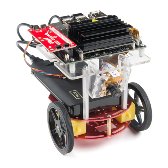
Assembly Guide for SparkFun JetBot AI Kit
Introduction
SparkFun's version of the JetBot merges the industry leading machine learning capabilities of the NVIDIA Jetson
Nano with the vast SparkFun ecosystem of sensors and accessories. Packaged as a ready to assemble robotics
platform, the SparkFun JetBot Kit requires no additional components or 3D printing to get started - just assemble
the robot, boot up the Jetson Nano, connect to WiFi and start using the JetBot immediately. This combination of
advanced technologies in a ready-to-assemble package makes the SparkFun JetBot Kit a standout, delivering one
of the strongest robotics platforms on the market. This guide serves as hardware assembly instructions for the two
kits that SparkFun sells; Jetbot including Jetson Nano & the Jetbot add-on kit without the NVIDIA Jetson Nano.
The SparkFun JetBot comes with a pre-flashed micro SD card image that includes the Nvidia JetBot base image
with additional installations of the SparkFun Qwiic Python library, Edimax WiFi driver, Amazon Greengrass, and
the JetBot ROS. Users only need to plug in the SD card and set up the WiFi connection to get started.
Note: We recommend that you read all of the directions first, before building your Jetbot. However, we
empathize if you are just here for the pictures & a general feel for the SparkFun Jetbot. We are also those
people who on occasion void warranties & recycle unopened instructions manuals. However, SparkFun can
only provide support for the instructions laid out in the following pages.
Advertisement

Related Manuals for sparkfun JetBot AI Kit


Summary of Contents for sparkfun JetBot AI Kit
- Page 1 Note: We recommend that you read all of the directions first, before building your Jetbot. However, we empathize if you are just here for the pictures & a general feel for the SparkFun Jetbot. We are also those people who on occasion void warranties & recycle unopened instructions manuals. However, SparkFun can...
- Page 2 Jetson Nano environment, which makes it easy to integrate more than 30 sensors (no soldering and daisy-chainable). The SparkFun Qwiic Connect System is an ecosystem of I C sensors, actuators, shields and cables that make prototyping faster and less prone to error. All Qwiic-enabled boards use a common 1mm pitch, 4-pin JST connector.
- Page 3 Breadboard Mini Self-Adhesive Red SparkFun Qwiic HAT for Raspberry Pi SparkFun JetBot Acrylic sidewall for camera mount SparkFun JetBot Acrylic Camera mount & 4x nylon mounting hardware Qwiic Cable - 100mm Qwiic Cable - Female Jumper (4-pin) Wheels & Tires - included as part of circular robotics chassis USB Micro-B Cable - 6"...
-
Page 4: Recommended Tools
A Note About Directions When we talk about the "front," or "forward" of the JetBot, we are referring to direction the camera is pointed when the Jetbot is fully assembled. "Left" and "Right" will be from the perspective of the SparkFun Jetbot. - Page 5 1. Circular Robotics Chassis Kit (Two-Layer) Assembly If you prefer to follow along with a video, check out this feature from the chassis product page. You do not need to use the included ball caster as a larger option has been provided for smoother operation. Product Showcase: Circular Robotics Chassis Assembly Product Showcase: Circular Robotics Chassis Assembly Start by attaching the chassis motor mount tabs to each of the "Shadow Chassis Motors (pair)"...
- Page 6 Install the brass colored standoffs included with the Circular Robotics Chassis Kit; two in the rear and one in the front. The rear of the SparkFun Jetbot will be on the side of the plate with the two "+" sign cut outs. The rear of the motor will be opposite the wheel where the spindle extends.
- Page 7 Your main chassis is now assembled! The Circular Robotics Chassis Kit also contains a very small caster wheel assembly, but we have included a larger metal caster ball to increase the stability of the SparkFun Jetbot. We will cover the installation of this caster ball later in the tutorial.
- Page 8 The aluminum stand offs should be pointing up as shown below. The SparkFun JetBot acrylic mounting plate is designed to have two of these aluminum standoffs in the front & one in the rear. We recommend the rear standoff on the left side of the chassis (as shown) so the 6 in microB usb cables that will be installed later can more easily span the gap needed to power the JetBot.
- Page 9 Install the caster wheel using the Phillips head screws and nuts included with the 3/8 in caster ball assembly. The holes on the caster assembly are spaced to fit snug on the innermost segment of the angular slots near the rear of the lower plate on the JetBot chassis.
- Page 10 Place all four nylon flathead screws through the camera & acrylic mounting plate prior to fully tightening the nylon nuts. This will ensure equal alignment across all four screws. Tighten the screws while holding the nuts with finger pressure in a rotating criss cross pattern; similar to how you tighten lug nuts on a car rim. Align one acrylic sidewall with the camera mounting plate as shown below ensuring that the widest section of the sidewall is oriented to the top of the camera mount where the ribbon cable extends.
- Page 11 This will ensure that there is plenty of room for the camera ribbon cable to pass around the assembly and up to the Jetson nano camera connector. Install four of the nylon standoffs to the top of the SparkFun Jetbot acrylic mounting plate using four of the included 1/4 in 4-40 Phillips head screws as shown below.
- Page 12 #3 noted as "configuration bits" on the back of the SparkFun serial controlled motor driver; see below. You will need to create a solder jumper on pad #3 only for the SparkFun Jetbot Image to...
- Page 13 "GRD" terminals for each unit share a bridge on one side of the breadboard. Utilize the included 2 in - 22 gauge solid core hookup wire (red) to bridge the "VCC" pin for the SparkFun microB Breakout to either (VIN) connection point on the SparkFun Serial Controlled Motor Driver as shown below.
- Page 14 4. Accessory Installation to Main Chassis Align the mounting holes on the SparkFun Micro OLED (Qwiic) with those on the back of the SparkFun Jetbot acrylic mounting plate. Install the Micro OLED using two 1/4 in 4-40 Phillips head screws and two 4-40 machine screw nuts.
- Page 15 Unpackage & install the USB Wifi adaptor into one of the USB ports on the Jetson nano Dev Kit. The drivers for this Wifi adaptor are pre-installed on the SparkFun Jetbot image. If you are making your own image, you will need...
- Page 16 Align the SparkFun pHat with the GPIO headers on the Jetson Nano Dev Kit so that the pHat overhangs the right hand side of the Jetbot. For additional information on hardware assembly of the SparkFun pHat, please reference the hookup guide here.
- Page 17 Daisy chain the polarized Qwiic connector on the other end of the (4-pin) Female Jumper Qwiic cable into the back of the SparkFun Micro OLED (Qwiic). Using the 100mm Qwiic Cable attach the SparkFun Micro OLED front Qwiic connector to the SparkFun pHat as shown.
- Page 18 Apply firm pressure to the battery pack to attach to the Jetbot chassis via the Dual Lock Velcro. Remove the micro SD card from the SD card adapter. Insert the micro SD card facing down into the micro SD card slot on the front of the Jetson Nano Dev Kit. Please see the next three pictures for additional details.
- Page 19 The USB ports on the back of the 10Ah battery pack has two differently colored ports. The black port (1A) is used to power the motor driver via the SparkFun microB breakout. Utilize one of the 6 in micro-B USB cables to supply...
-
Page 20: Software Setup
DO NOT format or flash a new image on the SD card; otherwise, you will need to flash our image back onto the card (instructions below). Your SparkFun Jetbot comes with a Pre-Flashed micro SD card. Users only need to plug in the SD card and set up the WiFi connection to get started. -
Page 21: Troubleshooting
Note:Running in the command line will overwrite the software sudo python3 setup.py install modifications for SparkFun's hardware in the kit. Troubleshooting In the event that you accidentally missed the instructions above, here are instructions to get back on track. Re-Flashing the SD card If you need to re-flash your SD card, follow the instructions from Step 1 Nvidia's guide. - Page 22 The "object following" jupyter notebook example won't work due to the required dependencies that had not been released by NVIDIA prior to the creation of the SparkFun JetBot image. These updates can be manually installed on your Jetson Nano with the JetPack 4.2.1 release.
- Page 23 ReconBot with the Tessel 2 Wireless Joystick Hookup Guide Build a robot with the Tessel 2 that you can control from A hookup guide for the SparkFun Wireless Joystick Kit. a browser on your phone or laptop. Building a Safe Cracking Robot Wireless Remote Control with micro:bit How to crack an unknown safe in under an hour.
Need help?
Do you have a question about the JetBot AI Kit and is the answer not in the manual?
Questions and answers