
Subscribe to Our Youtube Channel
Related Manuals for Woodcraft PantoRouter

Summary of Contents for Woodcraft PantoRouter
- Page 1 Assembly Guide www.PantoRouter.com Info@PantoRouter.com +1-877-333-7150 Copyright 2020 WoodCraft Solutions LLC...
- Page 2 You are responsible for your own safety. Read and understand the Assembly Guide, the How-To Guide and the Warning Label on the PantoRouter Failure to follow instructions or heed warnings may result in electric shock, fire, serious personal injury or property damage.
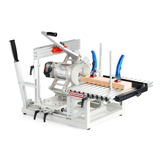
- Page 3 Basic Components of the PantoRouter™ 1. Table 2. Centering Scale Fence 3. T-Slot Lever Clamps 4. Template Holder 5. Thickness Gauge 6. Template Holder Locking Lever 7. Template Holder Support Frame 8. Depth Stops 9. Pantograph Carriage 10. Pantograph...
-
Page 4: General Assembly Diagram
General Assembly Diagram... - Page 5 The KITS box contains the hardware, small parts and hex wrenches needed to assemble the PantoRouter will also need an accurate square for checking alignment and a 5/16” or 8mm end wrench, socket or nut driver. A digital or analog caliper will help to dial-in the Thickness Gauge for ultimate precision. We recommend not using a battery-operated drill or impact driver for assembling the PantoRouter You’ll notice we use mostly recycled...
- Page 6 PantoRouter™Assembly Guide ©WoodCraft Solutions LLC, December 2020 We thank you for your PantoRouter™ purchase and we hope you find great pleasure in creating all kinds of traditional and innovative joinery. There’s no better jig for mortise and tenons, box joints and machine-cut dovetails, but this is just the beginning of the tasks you can master with the PantoRouter™.
- Page 7 Leave for now. Cut the straps holding the padding material but don’t Check the machined surfaces to make sure they’re cut the nylon tie straps holding the pantograph to the clean and smooth. If needed, remove paint but don’t carriage base yet. use sand cloth.
- Page 8 Using the hex wrench provided in Kit-9 tighten the Install the rubber feet to the bottom of the base frame cap screws to the plate nuts to secure the template without over-compressing the rubber. holder frame. Clip the wire ties to access these cap screws.
- Page 9 The Porter Cable 8902 router supplied with our Pro-Pack and All-In packages has a rack gear that is not used with the PantoRouter . To remove the two small screws and the gear, place the router on a solid surface and use significant downward pressure while Check the two table supports to be sure they’re clean...
- Page 10 Push the router forward until the base of the bevel on the router is aligned with the front face of the router mount. Rotate the router so the rotor lock button is aligned with the “m” in www.pantorouter.com¨ cast into the router mount. Tighten both router mount cap screws and locking nuts.
- Page 11 Choose the inch or metric side of the depth stop scale then mount it on the depth stop using a business card or four thicknesses of paper for clearance over the depth stop angle. Now that the basic assembly of the PantoRouter is complete, continue on for directions to: 1.
- Page 12 Calibrate the Template Holder The template holder frame assembly is aligned at the factory but can shift slightly in transit so the following procedure might be necessary to bring it back into perfect alignment. Check alignment using a square before loosening the screws to see if adjustment is needed.
- Page 13 The template and template holder must be coplanar to the table and the workpiece in order to produce high quality joinery. This can be quickly checked after the template holder support frame and template holder have been squared and trued. Cut a setup block from a piece of fine grain wood so it’s square on the end then stand it up on the operator’s side of the table.
- Page 14 Calibrate The PantoRouter™ For Ultra Precision If your centering jig test indicates a difference from one side of the table to the other, please follow the procedure here to calibrate your PantoRouter for precision operation every time. This only needs to be done once.
- Page 15 Setting the Thickness Gauge Cut a test piece about 1-1/2” square and about Insert one of the non-tapered 6mm guide bear- 18’ long. Make sure the sides are parallel and ing shafts into the center hole of the template there is no snipe on the ends. Mark one side holder.
- Page 16 Measure the shoulders of the workpiece and note which is higher, the top or bottom shoulder. The thickness gauge needs to be moved the full difference between the two measurements. In this case it’s 0.46 mm. Reference Gauge Thickness Gauge Raise the thickness gauge reference angle on the back of the support post and insert feeler gauge(s) as close to the desired move amount as possible.
- Page 17 Finding and Marking the Table Centerline The PantoRouter™ transfers the shape of the template mounted on the template holder to the workpiece locat- ed on the table. Aligning the template, router bit and workpiece are essential to accurate joinery, and this is...
- Page 18 Insert the non-tapered 6mm guide bearing shaft through the center hole of a template and into the centering hole in the template holder then mount either centering jig (full-round pointer or split-shaft) in the router collet. Plunge the pantograph carriage forward and lower the template holder so the tip of the centering jig rests gently on the top edge of the table.
- Page 19 Setting up the Centering Scale Fence Setting up the centering scale fence is super easy and due to the precision-machined centering pins, the fence will be dead-on 90° without any adjustment. Before assembly you’ll need to decide which scale to use. We recommend using the metric (CM) scale since you don’t really care the size when centering (the size was determined when you milled your wood), you just want to find the middle.
- Page 20 Mortise and Tenon Guide Bearing and Bit Selection Note: Use a 12mm Guide Bearing and 1/2” bit to make 5/16” tenons Formula to Create Custom Templates: (Tenon Thickness + Bit Diam) - Guide Bearing...
- Page 21 Accessories Available in the Online Store The auxiliary fence is very useful for setting and repeating angles. Set the angle using a sliding bevel gauge, lock it down and it’ll stay put for all of your cuts. The Monster Mortise and Tenon set is especially useful for outdoor projects using construction lumber and for applications where big mortise and tenons are needed like the stretcher on a trestle table.
- Page 22 1” end pieces or 1-1/4” end pieces to make hundreds of different sizes of mortise and tenon! Please see the Segmented Mortise and Tenon How-To Guide on the PantoRouter website for complete instructions on set-up and use of this template system.
- Page 23 Please see the Slot Mortise How-To Guide on the PantoRouter website for complete instructions on set-up and use of this template system.
- Page 24 Copyright 2020 - WoodCraft Solutions LLC Distributed in North and South America, New Zealand and Australia by: WoodCraft Solutions LLC www.PantoRouter.com Info@PantoRouter.com +1-877-333-7150...
Need help?
Do you have a question about the PantoRouter and is the answer not in the manual?
Questions and answers